Abstract
This work is focused on the failure modes and control strategies of a trial designed super long-span cable-stayed bridge (Abbr. CSB) with a main span of 1400 m under various seismic intensities, exploring the key characteristic of the failure modes of super high tower. Then several control strategies, such as the use of conventional viscous fluid dampers (Abbr. VFDs) and a new combination strategy comprising sacrificial inelastic links and conventional VFDs, are presented for the failure modes improvement and the seismic damage mitigation of the CSB under extreme earthquake (PGA = 1.0 g). It is found that the super high tower experiences an unexpected failure mode with double plastic hinges that shows a new characteristic on the tower failure in the transverse direction, which is different from that of the short- and medium-span cable-stayed bridge during earthquake excitation. Whereas the piers show a typical and expected flexural failure mode with only one plastic hinge in the transverse direction. Although conventional control strategies using the optimal VFDs can help to significantly reduce the seismic damage of the CSB, they cannot entirely make the tower satisfy seismic control targets. It is also observed that the new combination strategy can successfully improve the failure mode and seismic damage of the CSB that satisfies seismic control targets, the effects of proposed combination strategy on the CSB are superior to those of the convention control strategy with the optimal VFDs.
1. Introduction
In China, several sea-crossing projects including long-span bridges have been constructed or are being planned, some of which are located in strong seismic zones. A cable-stayed bridge (abbr. to CSB) is an advantageous and competitive type of long-span bridge because of its structural efficiency, aesthetic shape, economical construction, and ability to span long distances. However, such a structure, particularly a super long-span CSB, may respond with large displacement and suffer from damages to structural elements after strong earthquake as a result of its low natural frequency and low damping. For example, severe damage was concentrated on several bearings of an 885 m cable-stayed steel bridge in the 1995 Kobe earthquake [1], and the tower and pier of the Ji-Lu CSB were damaged by the 1999 Chi-Chi earthquake [2]. In addition, the retrofit of the damaged members would often require temporary closure of the bridge for days or weeks, even need more expensive and time consuming to rebuild. Thus, the seismic safety of long-span CSBs is a matter of great concern because they are usually the major arteries in local traffic networks.
Strong earthquakes caused the damage and even the collapse of civil infrastructures including bridges. Many researchers primarily focused on investigating the failure mode and collapse mechanism of bridges in both simulation and post-earthquake studies [3-6], especially for short and medium-span bridges. However, only the Ji-Lu CSB damaged during the 1999 Chi-Chi earthquake has promoted research into the seismic damage and failure modes of cable-supported bridges. The damage and failure of the Ji-Lu CSB were evaluated based on load capacity of structure, and the results were good agreement with the actual damage in earthquake [2]. The failure modes of various structural systems of the Bingzhou Yellow River Highway Bridge were investigated in the longitudinal direction, and indicating that the tower experienced a flexural failure mode with only one plastic hinge [7]. Nie et al. [8] studied the failure mode of the Runyang long-span suspension bridge in the longitudinal direction, and the tower shown to be in form of synchronal double plastic hinges. The failure mode of the trial designed super long-span CSB without considering pile-soil-structure interaction (abbr. to PSSI) effects was studied under earthquake and the tower shown double plastic hinges in the transverse direction [9]. Although many researches have been conducted on the seismic damages and failure modes of structures including long-span bridges in the longitudinal direction, studies on flexible structures are meager in the transverse direction, particularly for super long-span CSBs considering PSSI effects because such flexible structures can be prone to significant PSSI effects.
Recently, a larger number of CSBs have been built around the world, some of which locate in strong seismic zones. Consequently, they are easier to suffer from earthquake-caused damage. So, considerable attentions have been paid to the application and research of structural control technologies to mitigate the seismic damage of CSBs [10, 11]. Many studies have examined structural control strategies to reduce the seismic damage of CSBs in the longitudinal direction, such as passive control strategies with conventional VFDs [11-15]. These studies have shown that structural control technologies can significantly reduce the seismic damage and response of CSBs. However, the girders generally need to be constrained at the tower and pier locations to avoid any unexpected vibration induced by vehicles or wind in the transverse direction. This may cause very large force demands on substructures under earthquake excitations. Ye and Fan [16] reported the effects of control systems with VFDs on controlling the seismic response of a long-span CSB in the transverse direction. The effects of side retainers on the seismic response control of a CSB have been studied by Xu and Li [17]. In addition, the control system comprising fuse restraints and VFDs connecting the deck to the towers and acting in parallel was implemented in the Rion-Antirion Bridge to cope with strong seismic activity and fault displacement [18]. In recent years, new concepts and structural control strategies have been proposed to match the needs of performance-based seismic design; for example, to purposely design the damage locations of structures under strong earthquakes and to restrict damage within certain locations and magnitudes to simplify the subsequent repairs. These concepts and systems of structural seismic damage control have been applied to real long-span bridges [13, 19]. The new structural system using sacrificial supporting piers as energy dissipation components to protect towers from seismic damage was proposed by Sun and Xie [20]. The passive hybrid control system comprising the additional energy dissipation links and VFDs was reported in the reference [9], but the study did not consider the influences of the pile-soil interaction on the seismic responses. In addition, basic theoretical and dynamic analyses on soil-foundation have been reported in references [21, 22]. Comparison with the control technologies of CSBs in the longitudinal direction, very limited research has been conducted on CSBs in the transverse direction. Thus, further and intensive studies on the failure modes and control strategies of long-span cable-supported bridges in the transverse direction is very important, especially for super long-span CSBs with PSSI effects excited by extreme earthquake.
In this study, 3-D finite element modelling of a trial designed super long-span CSB, considering PSSI effects modelled as equivalent nonlinear springs, is conceived in OpenSees. Nonlinear time history analyses are performed to study the seismic damage and failure modes of the CSB under various seismic intensities in the transverse direction, particularly under extreme earthquake (PGA = 1.0 g). Two control strategies with the VFDs placed between the girder and tower as well as between the girder and pier are study on controlling the seismic damage of the CSB under extreme earthquake. In addition, the influence of the connection modes between the upper beam and tower on reducing the seismic damage of the tower is evaluated on the basis of the control strategy with the optimal VFDs. Finally, a new combination strategy, comprising the optimal VFDs and several additional inelastic links used as sacrificial energy dissipation devices, is proposed and verified in seismic damage mitigation and failure mode improvement of the CSB under extreme earthquake.
2. Seismic failure analysis procedure for bridge structures
2.1. Analytical model based on energy balance
For a generic bridge structure with passively controlled under earthquake excitations, the following dynamic system of nonlinear equation can be written:
In which , and are the relative displacement, relative velocity, and relative acceleration vectors, respectively; , and are the mass, damping, and time-varying stiffness matrixes, respectively; is the earthquake wave acceleration; and are the matrixes of assignment that refer the seismic and control forces to the associated degree of freedom; the forces vector, , generated by the passive devices, can be expressed in the following form:
In which and are the stiffness matrix and the damping matrix referred to the devices, respectively; whereas and are the displacements and the velocity of the couples of nodes linked by the devices, respectively.
Both sides of Eq. (1) simultaneously multiply by , in which denotes transposition of a vector . The energy equation of bridge structure, can be defined by the integral with respect to the duration of earthquake wave, which can be written as follows:
In which is the total input energy, is the instantaneous kinetic energy, is the cumulative damping energy, is the cumulative hysteretic energy, is the instantaneous elastic strain energy. and are the cumulative damping energy and hysteretic energy referred to the passive devices, respectively. The vector, , can be written as follows:
According to Eq. (1), the use of elasto-plastic analysis can yield the displacement, moment, and curvature vectors of bridge structure under given input waves, and can further gain the cumulative hysteretic energy dissipation, , and seismic damage indices of bridge members by Eqs. (5) or (6), presented in the following subsection.
2.2. Seismic damage indices
Under earthquake loading, the damage to and failure of a generic bridge structure are dependent on its deformation, strength and cumulative energy. In order to rationally reflect the elasto-plastic deformation and the effects repeated cycle loading caused by earthquake action, Park et al [23, 24] proposed that classic seismic structural damage can be expressed as a linear combination of the maximum deformation and the hysteretic energy. This may be represented in terms of a damage index [23, 24]:
In which is the maximum deformation under earthquake excitations, is the ultimate deformation under monotonic loading, is the calculated yield strength, is the non-negative parameter or energy dissipation factor.
Direct application of the damage model in Eq. (5) to a bridge structure or member requires the ultimate displacement of the corresponding bridge structure or member to be determined. However, the determination of bridge structure’s ultimate deformation is very difficult for a super high structure or structural member such as reinforced concrete (RC) tower of a long-span CSB. Therefore, Kunnath [25] presented a modified Park’s damage model with the yield moment and curvature replacing the yield force and displacement of Eq. (5). The elastic deformation is not taken into account in Eq. (6). The modified Park’s damage model can be expressed in following form:
In which is the maximum curvature of section under earthquake excitations, and is the ultimate curvature of section under monotonic loading, and is the calculated yield curvature and moment of the section, respectively. For a structural member with the compression and bending, the hysteretic energy, , can be obtained by the integral of the hysteretic curve of moment-curvature of structural members in plastic hinge zone.
2.3. Seismic failure criteria
To evaluate structural damage and safety under earthquake, rational seismic damage indices are required. A generic bridge structure, such as the CSB, is composed of different members and materials. Different members, such as RC tower and steel girder, require various seismic damage indices or failure criteria because they behave different mechanical property. Herein, several seismic damage indices and failure criteria are employed to quantitatively assess structural damage and to study the control strategies effects. For RC structures easily experiencing plastic deformation under strong earthquake, Park damage model is widely adopted to describe degree of structural seismic damage. Corresponding damage levels are divided into No Damage (DS1), Minor Damage (DS2), Moderate Damage (DS3), Severe Damage (DS4) and Collapse or Local Failure (DS5); the damage indices are 0-0.1, 0.1-0.25, 0.25-0.40, 0.4-1.0 and ≥1.0, respectively; damage index >1.0 signifies collapse of the structure or local failure of the member [26]. For the steel girder and stay cable, strength-based criteria, including the yield and allowable stress, are employed to evaluate whether they are beyond the elastic range. Yield stress of 460 MPa and allowable stress of 970 MPa are utilized as the critical damage value of the girder and the stay cable, respectively.
3. Seismic control strategies and targets for bridge structures
3.1. Seismic control strategies
For a passively controlled bridge structure, Eq. (3) indicates that the input energy, , can eventually transform into the damping energy, , the hysteresis energy, , the supplemental damping energy, , the supplemental hysteresis energy, , the kinetic energy, , and the elastic strain energy, . The kinetic energy and elastic strain energy diminish near the end of an earthquake. In addition, the structural seismic damage defined by Eqs. (5) or (6) is primarily dependent on the structure’s deformation responses and absorbed hysteretic energy during earthquakes. It is also indicated that a reduction in structural damage can be achieved by decreasing the deformation/curvature responses and hysteresis energy demands, or conversely, by increasing the deformation/curvature and hysteresis energy capacity. Herein, several control strategies may have an effect on reducing the structural seismic damage as follows: (1) improving structural deformation or hysteresis energy capacity; (2) increasing structural damping energy; (3) adding passive energy dissipation device, such as metallic yield damper or viscous fluid damper (VFD); (4) adding nonstructural components used as sacrificial energy dissipation device, such as shear link or buckling restrained brace; (5) by using a combination of these methods.
As mentioned above, the first control strategy, increasing structural deformation/curvature or hysteresis energy capacity, may result in uneconomical structure because of the requirements of the sectional dimensions enhancement and the material increase. The second control strategy, increasing the structural damping energy, is also very difficult because structural damping embodies its own immutable, inherent characteristics. Hence, a viable option is the use of control strategies (3), (4), or (5), resulting in the mitigation of the seismic damage and the improvement of the seismic performance of the structure. Therefore, three passive control systems with the VFDs and a passive hybrid control system incorporating the VFDs and nonstructural components are presented in the following analyses.
3.2. Seismic control targets
For the seismic damage control strategies mentioned above, the damage control objective is as follows: the tower should be controlled to minor damage, which is easily repaired after earthquakes; the corresponding Park damage index is less than 0.25; and the curvature ductility factor is below 3. The pier can be controlled to moderate damage to dissipate more input energy by the plastic deformation, the corresponding Park damage index is less than 0.40 and the curvature ductility factor should not be above 15. Furthermore, the pier suffering severe damage will be within an acceptable range, as long as it is able to carry vertical load. The girder and stay cable should remain elastic, whose stress demands are below their own critical damage values.
4. Seismic damage and failure modes analyses
4.1. Description of super long-span cable-stayed bridge
A trial designed bridge, as shown in Fig. 1, is a super long-span CSB with a main span of 1400 m [27]. The bridge has an overall length of 2672 m, the span arrangements of which are 150 + 176 + 310 + 1400 + 310 + 176 + 150 m. All RC piers, each with a height of 60 m, consist of four supporting piers (No. 2, No. 3, No. 6 and No. 7 piers) and two side piers (No. 1 and No. 8 piers).
Fig. 1Elevation view of cable-stayed bridge with main span of 1400 m (unit: m)
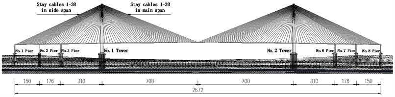
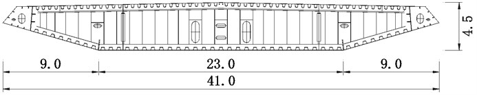
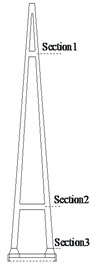
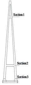
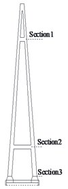
A-shaped RC tower with height of 357 m is shown in Fig. 2, both columns of which are connected by the upper and lower beams to strengthen its transverse stiffness. Baseline cross section of the main girder, 41.0 m wide and 4.5 m high, is an aerodynamically shaped closed box steel girder, as depicted in Fig. 3. There are 304 (38×4×2) stay cables with semi-harp configuration in total, and the longest one is close to 750 m. The pile groups supporting No. 1-No. 3 and No. 6-No. 8 piers, each pile with a diameter of 2.5 m, consist of 19 piles, 19 piles, 36 piles, 36 piles, 19 piles and 19 piles. The length of them are 108 m, 108 m, 98 m, 101 m, 110 m and 108 m, respectively. The pile groups supporting No. 1 and No. 2 towers have 162 piles with a diameter of 2.5 m, and the length of them are 117 m and 114 m, respectively. Due to the scarcity of the geologic structure, the geologic condition of the CSB is same as that of the Sutong bridge, which can rationally reflect the character of the site condition in coastal region.
Fig. 2Elevation view and cross section of tower (unit: m)
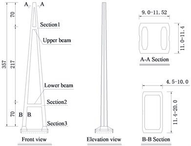
Fig. 3Baseline cross section of steel girder (unit: m)
4.2. Finite element modelling
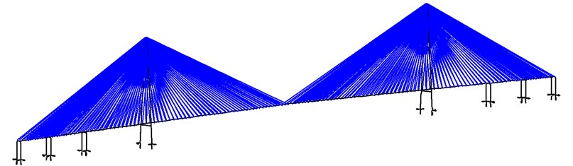
A full 3-D finite element modelling including equivalent nonlinear springs (Fig. 4), considering geometric and material nonlinearities, was conceived to analyze nonlinear seismic response of the CSB in OpenSees [28]. The RC towers and piers were modelled as the fiber elements considering axial force-moment interaction [29]. The main girder was modelled as the elastic beam element. The stay cables were modelled as the truss element with the concept of equivalent elastic modulus, and the connections between the stay cables and tower as well as between the stay cables and girder were modelled as the rigid link. The equivalent nonlinear springs were modelled as the zero-length element, the stiffness and yield strength of which were determined by seismic performance analyses of the pile-soil finite element modelling using push-over analysis, the detailed analyses progress and parameters of the equivalents springs were as referenced in reference [30]. A modified Menegotto and Pinto model [31] including strain hardening was employed for the constitutive modeling of the reinforcing steel bars, and a Mander model [32] considering the effective confinement of stirrups was applied for modeling the concrete. Rayleigh damping was adopted in the 3-D model and the damping ratio was assumed to be 3 % according to the standard code [33].
The connections between the towers and the girder were assumed to be free in the longitudinal direction, as were the connections between the piers and the girder. The displacement restraint was transversely modelled in the 3-D finite element modelling, which was considered to be a constrained system in the following analyses. Furthermore, the effect of the foundation on the seismic response of the CSB was modeled by equivalent nonlinear springs. Hence, the boundary conditions were modelled as translationally and rotationally spring elements in the three orthogonal directions at the bases of the towers and piers, as shown in Fig. 4.
The dynamic characteristics of the CSB were obtained according to the 3-D finite element modelling. The first three modal periods of the CSB in the transverse direction are 14.977, 5.951 and 5.920 s, respectively. In addition, the detailed dynamic characteristics of the CSB were reported in reference [34].
Fig. 43-D finite element modelling of CSB with equivalent nonlinear springs
4.3. Input waves
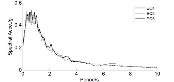
Three artificial waves, previously generated for another long-span bridge, are adopted for the trial designed CSB because of the scarcity of the geologic structure, as plotted in Fig. 5. Each wave includes long period components that have significant influence on this flexible structure, and corresponding acceleration response spectra under 3 % damping are shown in Fig. 6. The peak ground acceleration (PGA) of 0.2 g is representative of the design earthquake wave according to the seismic design guideline [33] and the assumption that the CSB is located in seismic fortification intensity 8.
Fig. 5Acceleration time histories of three artificial waves
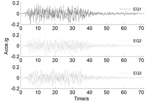
In addition, other earthquake intensities are simulated by amplifying the PGA 2, 4, and 5 times to investigate the seismic damage and failure modes of the CSB in the transverse direction, particularly for a PGA of 1.0 g representing an extreme earthquake. Each input wave is assumed to act uniformly at all supports along the transverse direction of the CSB, and the influence of the longitudinal and vertical earthquake is neglected in this study. Thus, the CSB was subjected to a suite of uniaxial input wave with gradually increasing intensities. In the following analyses, the average demands are obtained and shown for the CSB subjected to three input waves.
Fig. 6Acceleration response spectra of three artificial waves
4.4. Seismic damage and failure modes analyses
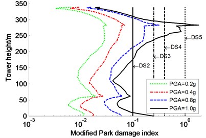
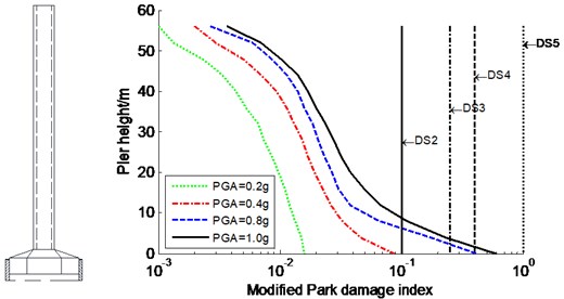
The seismic damage and failure modes of the constrained system designated were studied for the CSB subjected to various seismic intensities of three input waves in the transverse direction. The average modified Park damage indices distribution along the tower and pier are shown in Fig. 7-Fig. 8, respectively. Meanwhile, DS2, DS3, DS4, and DS5 are also plotted in Fig. 7-Fig. 8 to visually assess the seismic damage, which present critical value between both damage stages (similarly hereinafter). However, the results of the partial anchorage region (341-357 m) of the tower is not plotted because this region is within elastic range. Furthermore, a secondary damage index, such as ductility factor, was also introduced to evaluate the seismic damage of super-high RC members. Table 1 only lists the curvature ductility factors at key sections of the tower and piers.
Fig. 7Average modified Park damage indices distribution along tower for constrained system
a)
b)
As shown in Fig. 7-Fig. 8, in the cases of PGA of 0.2 g and 0.4 g, the modified Park damage indices of the tower and piers are less than 0.1, indicating that they are in elastic range and the seismic performance meets seismic design targets based on the standard code [33]. Applying input wave with PGA of 0.8 g has a large impact on the modified Park damage indices of the tower and piers: section 1 of the tower, the No. 2 and No. 3 piers bases experience moderate damage, and the No. 1 pier base suffers from severe damage; corresponding damage indices are 0.314, 0.293, 0.382 and 0.421, respectively. Increasing the PGA to 1.0 g significantly increases the seismic damage along the tower and piers. The vulnerable locations of the tower are still confined to sections 1 and 3 (Fig. 2), which suffer local failure and moderate damage, respectively. Especially of notes, the time difference of both sections getting the maximum damage index is only 1.02 s. The modified Park damage indices at the bases of No. 1, No. 2, and No. 3 piers reach 0.606, 0.452, and 0.564, respectively, which are larger than severe damage value of 0.4. The curvature ductility factors at key sections of the tower and piers increase significantly with the PGA increasing (Table 1). In the case of extreme earthquake (PGA = 1.0 g), sections 1 and 3 (Fig. 2) of the tower and the bases of the piers suffer from severe damage or moderate damage according to curvature ductility factor-based damage criteria (Table 2) determined by the strain criteria. Consequently, it is relatively unsafe to evaluate the seismic damage of the tower and piers by using the curvature ductility factor, rather than by the modified Park damage index. So, only the modified Park damage index is used to assess the effectiveness of control strategies in the following section.
Fig. 8Average modified Park damage indices distribution along pier for constrained system
a) No. 1 pier
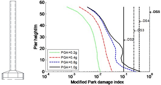
b) No. 2 pier
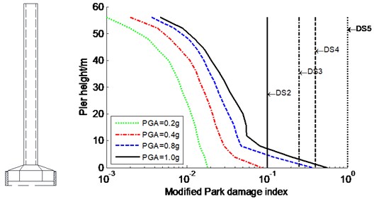
c) No. 3 pier
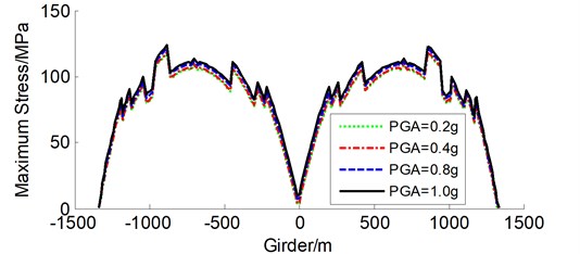
Table 3 and Fig. 9 show the maximum stress demands of typical stay cables 1#, 14#, 25#, and 38# in the side and main spans (see Fig. 1) and the steel girder under various PGAs, respectively. The maximum stress demands of the typical stay cables and steel girder under extreme earthquake are 751.3 MPa and 123.5 MPa, respectively, which are lower than allowable values. This indicates that the stay cables and steel girder are below the elastic limits, which are relatively large redundant. It is concluded that sections 1 and 3 (Fig. 2) of the tower for the constrained system almost simultaneously suffer from local failure and moderate damage, respectively, under extreme earthquake according to Modified Park damage indices, and the tower experiences an unexpected failure mode with double plastic hinges in the transverse direction. This failure mode does not enable the tower to form successively plastic hinge mechanism, which may be different from that of the short- and medium-span CSBs. Therefore, more attention should be paid to the unexpected failure mode when conducting seismic design of long-span CSBs. The piers base also suffers from damage, whereas other regions of the piers remain elastic, indicating that the pier shows a typical flexural failure mode with one plastic hinge. Consequently, the above-mentioned sections are vulnerable to damage under strong earthquake and certain damage control strategy should be suggested in the following section to improve the seismic performance.
Table 1Curvature ductility factor at key sections of tower and piers for constrained system
PGA | Tower | No. 1 pier | No. 2 pier | No. 3 pier | ||
Section 1 | Section 2 | Section 3 | Base section | Base section | Base section | |
0.2 g | 0.321 | 0.216 | 0.125 | 0.562 | 0.438 | 0.639 |
0.4 g | 0.641 | 0.290 | 0.195 | 2.834 | 1.257 | 2.867 |
0.8 g | 2.353 | 0.609 | 0.616 | 12.020 | 8.659 | 10.836 |
1.0 g | 11.13 < 13.2* | 0.821 < 12.8* | 2.244 < 12.7* | 17.472 < 42.9* | 13.339 < 42.9* | 16.670 < 42.9* |
Note: *denotes the ultimate curvature ductility factor | ||||||
Table 2Curvature ductility factor-based damage criteria at key sections of tower and piers
Damage | Damage index of curvature ductility factor | |||
Section 1 | Section 2 | Section 3 | Pier base section | |
No damage (DS1) | <1.0 | <1.0 | <1.0 | <1.0 |
Minor damage (DS2) | [1.0, 3.3) | [1.0, 3.5) | [1.0, 3.4) | [1.0, 7.1) |
Moderate damage (DS3) | [3.3, 10.5) | [3.5, 10.3) | [3.4, 10.2) | [7.1, 22.6) |
Severe damage (DS4) | [10.5, 13.2) | [10.3, 12.8) | [10.2, 12.7) | [22.6, 42.9) |
Local failure/collapse (DS5) | ≥13.2 | ≥12.8 | ≥12.7 | ≥42.9 |
Table 3Maximum stress demands of typical stay cables for constrained system
PGA | Typical stay cables in side span / MPa | Typical stay cables in main span / MPa | ||||||
1# | 14# | 25# | 38# | 1# | 14# | 25# | 38# | |
0.2 g | 602.0 | 643.8 | 651.4 | 576.3 | 700.5 | 665.2 | 667.1 | 562.9 |
0.4 g | 605.9 | 646.6 | 655.4 | 584.6 | 711.4 | 679.4 | 682.0 | 571.2 |
0.8 g | 618.5 | 656.0 | 664.9 | 599.4 | 737.1 | 709.5 | 711.8 | 588.1 |
1.0 g | 628.2 | 664.2 | 679.7 | 607.8 | 751.3 | 730.7 | 732.2 | 598.5 |
Fig. 9Maximum stress envelope curves of girder for constrained system
5. Effectiveness of control strategies on seismic damage and failure modes
Several control strategies, such as additional VFDs used as passive energy dissipation devices and inelastic links used as sacrificial energy dissipation components, are studied to improve the seismic damage and failure modes of the CSB under extreme earthquake (PGA = 1.0 g), the effectiveness of which on the seismic response of the CSB is further evaluated only based on the modified Park damage indices of the tower and piers because of the steel girder and stay cables remaining elastic according to above analyses.
5.1. Effects of viscous fluid dampers on seismic damage and failure modes
The conventional VFDs are adopted for the control strategies because of its high energy dissipation capacity. Moreover, the effects of VFDs on controlling the members are primarily dependent on the installation locations and parameters of them. Thus, both control strategies, named Strategy A and Strategy B, are presented in this section, the parameters of which are investigated to determine the optimal control effects of the VFDs, as listed in Table 4. In strategy A, the VFDs are only installed between the tower and girder in the transverse direction, damping coefficient of which is varying from 0 to infinity, as shown in Fig. 10(a). In strategy B, the VFDs are installed between the tower and girder as well as between the pier and girder in the transverse direction, damping coefficient of which is also varying from 0 to infinity at the pier locations, while damping coefficient of the VFDs installed at the tower locations is determined through parametric sensivity analyses of strategy A, as depicted in Fig. 10(b). The velocity exponent is assumed to 0.5 for all VFDs that are modelled as the zero-length element, and the mechanical behavior of the material of the VFDs is modelled as the viscous material in OpenSees. The dynamic characteristics of both control strategies are different because of the change of the boundary conditions. As a result, the first mode periods of strategy A and B are 27.465 s and 59.750 s, respectively, in the transverse direction.
Fig. 10VFDs installed at tower and pier locations for strategies A and B (plan view)
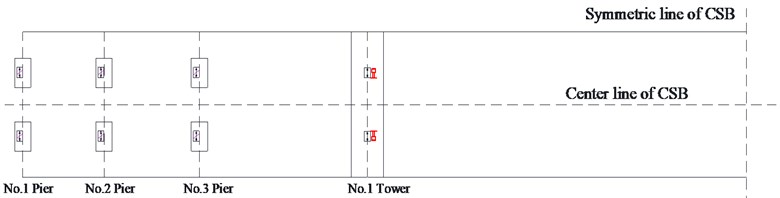
a) VFDs installed at tower location for strategy A
b) VFDs installed at tower and pier location for strategy B

The above analyses results indicate that sections 1 and 3 of the tower and the pier bases are easier to suffer from damage and even local failure. Herein, the modified Park damage indices of these sections are only employed to evaluate the effects of the installation locations and damping coefficient of the VFDs on alleviating the seismic damage of the tower and pier under extreme earthquake (PGA = 1.0 g), as listed in Table 4. The deformation and force demands of the VFDs are listed in Table 5. However, the deformation and force demands of certain VFDs are unavailable in strategies A and B because damping coefficient is increased to infinity.
Table 4Effects of VFDs on seismic damage at key sections of tower and piers
Control strategies | at tower (kN/(m·s)0.5) | at pier (kN/(m·s)0.5) | Modified park damage indices of tower | Modified park damage indices of pier | ||||
Section 1 | Section 2 | Section 3 | No. 1 pier | No. 2 pier | No. 3 pier | |||
Strategy A | 0 | ∞ | 0.657 | 0.090 | 0.067 | 0.396 | 0.322 | 0.503 |
4000 | 0.608 | 0.082 | 0.068 | 0.372 | 0.343 | 0.440 | ||
8000 | 0.704 | 0.079 | 0.073 | 0.385 | 0.365 | 0.424 | ||
12000 | 0.757 | 0.081 | 0.078 | 0.414 | 0.383 | 0.436 | ||
16000 | 0.832 | 0.082 | 0.084 | 0.457 | 0.395 | 0.466 | ||
20000 | 0.909 | 0.082 | 0.093 | 0.494 | 0.410 | 0.486 | ||
24000 | 0.979 | 0.082 | 0.107 | 0.520 | 0.418 | 0.505 | ||
∞ | 1.805 | 0.089 | 0.251 | 0.606 | 0.452 | 0.564 | ||
Strategy B | 16000 | 0 | 0.324 | 0.075 | 0.072 | 0.451 | 0.463 | 0.442 |
1000 | 0.635 | 0.079 | 0.078 | 0.089 | 0.088 | 0.110 | ||
2000 | 0.704 | 0.082 | 0.080 | 0.214 | 0.208 | 0.214 | ||
3000 | 0.742 | 0.082 | 0.081 | 0.302 | 0.305 | 0.328 | ||
4000 | 0.768 | 0.082 | 0.082 | 0.343 | 0.344 | 0.377 | ||
∞ | 0.832 | 0.082 | 0.084 | 0.457 | 0.395 | 0.466 | ||
As can be seen from Table 4, damping coefficient of the VFDs in strategy A, varying from 0 to infinity, has a notable effect on the seismic damage at sections 1 and 3 of the tower and at the bases of No. 1, No. 2 and No. 3 piers, whereas it has a minimal influence on the seismic damage at section 2 of the tower. Moreover, the seismic damage indices at section 1 of the tower and at the bases of No. 1 and No. 3 piers firstly decrease and then increase with damping coefficient of the VFDs increasing, indicating that damping coefficient of the VFDs exists an optimal value. The maximum deformation demands of the VFDs gradually reduce and the maximum force demands gradually increase as damping coefficient increased, as listed in Table 5. It can be found that damping coefficient , 16000 kN/(m·s)0.5, is better than others in strategy A balancing both the seismic damages of the tower and piers and the VFDs demands, corresponding maximum deformation and force demands of the VFD are 1.059 m and 3.955×10⁴ kN, respectively. It was reported that the largest force and stroke requirements of the special dampers for the Messina Strait Bridge were a total load capacity of 8.0×10⁴ kN and a ±2.0 m stroke, respectively [35]. Therefore, the manufactured VFDs are available for this purpose. Compared with the results of the constrained system, the optimal damping coefficient ( 16000 kN/(m·s)0.5) in strategy A reduces the maximum damage indices at sections 1 and 3 (Fig. 2) of the tower by 54 % and 67 %, respectively. As a result, section 3 only experiences elastic response, whereas section 1 is subjected to severe damage.
As listed in Table 4, damping coefficient of the VFDs installed between the pier and girder in strategy B, varying from 0 to infinity, has an obviously adverse effect on section 1 of the tower and has a significant impact on the bases of No. 1, No. 2 and No. 3 piers, while it has a little influence on sections 2 and 3 of the tower. The seismic damage index at section 1 of the tower increases as damping coefficient increased. The seismic damage indices at the base of No. 1, No. 2 and No. 3 piers firstly decrease and then increase with damping coefficient increasing, illustrating that damping coefficient of the VFDs exists an optimal value. In addition, the maximum deformation demands of the VFDs monotonically reduce, in reverse, the maximum force demands increase, as listed in Table 5. It is revealed that damping coefficient 2000 kN/(m·s)0.5 of the VFDs installed at the pier locations is better than others in strategy B balancing both the seismic damages of the tower and piers and the VFDs demands. Compared to the results of the constrained system, the optimal damping coefficient ( 2000 kN/(m·s)0.5) in strategy B reduces the seismic damage index at section 1 of the tower by up to 60 %, however, the section is still subject to severe damage. Thus, the control strategies cannot entirely control the seismic damage of the tower, and the tower does not meet damage control targets and need to be further studied by other control strategies. The possible reasons are that: (1) the partial inertia force of the girder transferred to the tower by the cables increases slightly because of the connections between the tower and girder changing; (2) the upper beam may lead to the stress concentration at section 1 of the tower. The optimal damping coefficient ( 2000 kN/(m·s)0.5) in strategy B reduces the maximum damage indices at the bases of No. 1, No. 2, and No. 3 piers by up to 65 %, 54 %, and 62 %, respectively, comparison to the results of the constrained system. Consequently, the controlled piers suffer moderate damage which satisfy seismic control targets.
Table 5Maximum deformation and force demands of all VFDs
Control strategies | at towers (kN/(m·s)0.5) | at piers (kN/(m·s)0.5) | Damper deformation / m | Damper force / (104 kN) | ||||||
Tower | No. 1 pier | No. 2 pie | No. 3 pier | Tower | No. 1 pier | No. 2 pier | No. 3 pier | |||
Strategy A | 0 | ∞ | 5.039 | / | / | 0 | / | / | / | |
4000 | 2.613 | / | / | 1.390 | / | / | / | |||
8000 | 1.738 | / | / | 2.441 | / | / | / | |||
12000 | 1.236 | / | / | 3.279 | / | / | / | |||
16000 | 1.059 | / | / | 3.955 | / | / | / | |||
20000 | 0.920 | / | / | 4.507 | / | / | / | |||
24000 | 0.798 | / | / | 4.962 | / | / | / | |||
∞ | / | / | / | / | / | / | / | / | ||
Strategy B | 16000 | 0 | 1.509 | 5.852 | 4.514 | 3.199 | 4.391 | 0 | 0 | 0 |
1000 | 0.978 | 1.558 | 1.537 | 1.481 | 3.792 | 0.484 | 0.480 | 0.469 | ||
2000 | 0.968 | 0.655 | 0.721 | 0.939 | 3.819 | 0.679 | 0.700 | 0.692 | ||
3000 | 0.980 | 0.360 | 0.412 | 0.569 | 3.875 | 0.791 | 0.848 | 0.820 | ||
4000 | 0.998 | 0.223 | 0.270 | 0.361 | 3.906 | 0.861 | 0.954 | 0.910 | ||
∞ | 1.059 | / | / | / | 3.955 | / | / | / | ||
5.2. Influences of connection modes of upper beam on seismic damage and failure modes
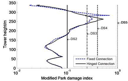
From the above analyses, the tower still suffers from severe damage even if the optimal VFDs were installed at the tower and pier locations, which did not satisfy seismic control targets. One of possible causes is the connection stiffness between the upper beam and tower leading to stress concentration of the tower. Herein, only the connection stiffness between both members decreases to zero on the basis of strategy B with the optimal VFDs, namely the connection modes between both members change from fixed connection to hinged connection, as depicted in Fig. 11. The nonlinear time history analyses are performed to evaluate the influence of the connection between both members on the seismic damage of the tower under extreme earthquake (PGA = 1.0 g). The modified Park damage indices distribution along the tower is shown in Fig. 12, where “Fixed connection” and “Hinged connection” represent the fixed and hinged connections between the upper beam and tower on the basis of strategy B with the optimal VFDs, respectively. Whereas the seismic damage and demands of other members, such as piers and VFDs, are not plotted and discussed because the change of the connection stiffness between both members has few influence on the seismic response of them.
Compared with the results of “Fixed connection”, “Hinged connection” reduces the modified Park damage index at section 1 of the tower by 64 %, while has little influence on the seismic damage at sections 2 and 3 of the tower. The modified Park damage indices are 0.240, 0.079, and 0.080, respectively, which are less than the moderate damage value of 0.25 or even the minor damage value of 0.1, indicating that the sections meet seismic control targets based on seismic damage criteria. However, it is noted that several new sections nearby section 1 are subjected to unexpected severe damage, such as the modified Park damage indices of the sections at tower height 257 m, 263 m, and 269 m are 0.407, 0.525, and 0.40, respectively, which do not satisfy seismic control targets. Anyway, “Hinged connection” can effectively mitigate the seismic damage distribution along the tower to a certain degree, for instance, the maximum modified Park damage index of the section at tower height 263 m for “Hinged connection” is 75 % that of section 1 of the tower for “Fixed connection”. It is clearly concluded that the seismic damage of the tower does not meet seismic control target when adopting the hinged connection between the upper beam and tower. Thus, the tower will be further investigated to meet seismic control targets and improve its failure modes by using other control strategies in following subsection.
Fig. 11Both connection modes between upper beam and tower
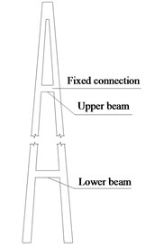
a)
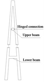
b)
Fig. 12Influence of connection modes between upper beam and tower on modified Park damage indices distribution along tower
a)
b)
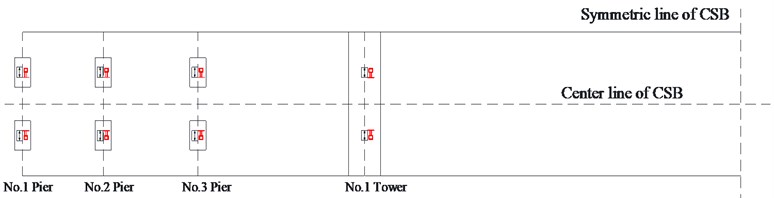
5.3. Effects of inelastic links on seismic damage and failure modes
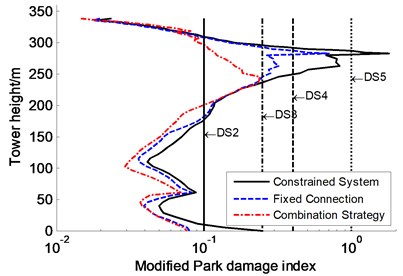
Additional inelastic links are applied to A-shape tower of the CSB on the basis of strategy B with the optimal VFDs located between the tower and girder as well as the pier and girder, the effects of which on the seismic damage of the tower are primarily dependent on the main parameters of them. Therefore, the optimal parameters of the inelastic links, including the flexural stiffness, yielding moment, and installation locations and amounts, are obtained from parametric sensitivity analyses, which are used to design the inelastic links made of low-yield steel, as shown in Fig. 13. And local buckling of the inelastic links is also verified according to the guidelines [36]. However, the detailed results are not presented in this paper. Then nonlinear time history analyses are performed to study the influence of the inelastic links on the seismic damage and failure modes of the tower for the CSB subjected to extreme earthquake (PGA = 1.0 g). The modified Park damage indices distribution along the tower is shown in Fig. 14, in which “combination strategy” represents the control strategy combining the inelastic links and the optimal VFDs in strategy B. In addition, the maximum moment, transverse shear force and transverse displacement of the tower are also shown in Fig. 15. Whereas the seismic damage and demands of other members, such as piers and VFDs, are not shown and discussed because the inelastic links have few influence on their seismic response. The results of strategy B with the optimal VFDs (named “Fixed Connection” in Section 5.2) and the constrained system are plotted in Fig. 14 and Fig. 15 for comparison.
Fig. 13Inelastic links installed on tower
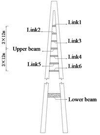
a) Inelastic links installed for tower
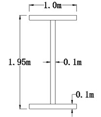
b) Cross section of inelastic link
Fig. 14Effects of inelastic links on controlling modified Park damage indices distribution along tower
a)
b)
Fig. 15Influences of inelastic links on seismic response along tower
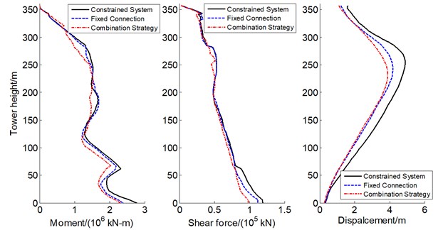
It can be seen in Fig. 14 that the combination strategy enables the tower to only experience minor damage and even no damage, such as the maximum modified Park damage index is only 0.238 at tower height 245 m, and 0.12 at section 1 of the tower, which are less than moderate damage value of 0.25. Furthermore, the combination strategy can effectively decrease the moment, transverse shear force and transverse displacement of the tower, such as the maximum moment and shear force at tower base reduce approximately 20 % comparison with the results of the constrained system, and the maximum displacement at tower height 251 m decreases 23 %, as shown in Fig. 15. It is concluded that the combination strategy can effectively control the seismic damage and improve the failure modes of the tower so as to increase the collapse resistant capacity of the CSB, which enable the CSB to satisfy the seismic control target according to seismic damage criteria.
6. Conclusions
Nonlinear time history analyses are carried out to study the failure modes and seismic damage of the CSB considering PSSI effects under various seismic intensities. Several control strategies are investigated for the improvement of failure modes and the mitigation of seismic damage of the CSB under extreme earthquake. The findings from the numerical results are as follows: (1) the super high tower experiences an unexpected failure mode with double plastic hinges under extreme earthquake, confined to the joint region between the upper beam and tower and the tower base, which is clearly different from that of short- and medium-span CSBs, such as the Ji-Lu CSB, during actual earthquake excitations. This failure mode shows a new characteristic of the tower failure as a result of the increase of the tower height and the contribution of the higher mode shapes. Whereas the piers show a typical flexural failure mode with only one plastic hinge concentrated at the pier base. The steel girder and stay cables are still in the elastic range and have large redundancy capacity under extreme earthquake. (2) The control strategies with the optimal VFDs placed at the tower and pier locations can help to significantly reduce the seismic damage of the CSB, such as the tower and piers. The hinge connection between the upper beam and tower also has a large effect on alleviating the seismic damage of the tower. But both control strategies cannot successfully control the seismic damage so that the tower cannot entirely satisfy seismic control targets. (3) The effects of the proposed new combination strategy on the improvement of failure mode and the mitigation of seismic damage of the CSB are superior to those of the conventional control strategies with the optimal VFDs. As a result, the proposed combination strategy can effectively improve the failure mode and seismic performance of the CSB under extreme earthquake so as to enable the CSB to only experience minor damage and even no damage and to meet seismic control targets. It is also demonstrated that the proposed combination strategy is feasible and effective on the CSB.
References
-
Nagasawa M., Sumi K., Tasaki K., Iemura H., Seismic retrofit of the all-free type cable-stayed Higashi-Kobe bridge with new energy dissipation devices. 5th World Conference on Structural Control and Monitoring, Tokyo, 2010.
-
Zhou Z. J. Study of Evaluation and Retrofitted for Seismic Damage of Ji-Lu Cable-Stayed Bridge. National Taiwan University, Taiwan, 2004.
-
Kunnath S. K., Gross J. L. Inelastic response of the cypress viaduct to the Loma Prieta earthquake. Engineering Structures, Vol. 17, Issue 7, 1995, p. 485-493.
-
Zayati F., Mahin S. A., Moehle J. P. Experimental and Analytical Evaluation of a Retrofit Double-Deck Viaduct Structure. Department of Civil Engineering of University of California, Berkeley, 1996.
-
Bruneau M. Performance of steel bridges during the 1995 Hyogoken-Nanbu (Kobe, Japan) earthquake – a North American perspective. Engineering Structures, Vol. 20, Issue 12, 1998, p. 1063-1078.
-
Sun L. M., Qin D., Fan L. C. A New model for collapse analysis of reinforced concrete bridge. China Civil Engineering Journal, Vol. 35, Issue 6, 2002, p. 53-58.
-
Liu J. L. Study of Control for Seismic Damage Modes of Cable-Stayed Bridge with Multi-Tower. Harbin Institute of Technology, Harbin, 2009.
-
Nie L. Y., Zhang L., Li S. J. Study of the longitudinal failure pattern of long-span suspension bridges under earthquake. China Civil Engineering Journal, Vol. 44, Issue 4, 2011, p. 91-97.
-
Xie W., Sun L. Passive hybrid system for seismic failure mode improvement of a long-span cable-stayed bridges in the transverse direction. Advances in Structural Engineering, Vol. 17, Issue 3, 2014, p. 399-411.
-
Chen Y. Q., Ma L. Z. Design and evaluation of limited displacement of damper Sutong Yangtze River Bridge. Modern Transportation Technology, Vol. 5, Issue 4, 2008, p. 20-24.
-
Seim C. The seismic retrofit of the Golden Gate bridge. Proceedings of the First PRC-US Workshop on Seismic Analysis and Design of Special Bridges, Shanghai, 2003.
-
Ali H.-E.-M., Abdel Ghaffar A.-M. Seismic energy dissipation for cable-stayed bridges using passive devices. Earthquake Engineering and Structural Dynamics, Vol. 23, Issue 8, 1994, p. 877-893.
-
Combault J., Pecker A., Teyssandier J.-P., Tourtois J.-M. Rion-Antirion bridge, greece-concept, design, and construction. Structural Engineering International, Vol. 15, Issue 1, 2005, p. 22-27.
-
Ye A. J., Fan L. C. Seismic response reduction of a super-long-span cable-stayed bridge by additional damper. Journal of Tongji University (Natural Science), Vol. 34, Issue 7, 2006, p. 859-863.
-
Vader T. S., Mcdaniel C. C. Influence of dampers on seismic response of cable-supported bridge towers. Journal of Bridge Engineering, Vol. 12, Issue 3, 2007, p. 373-379.
-
Ye A. J., Fan L. C. Lateral constraint systems for super-long-span cable-stayed bridge. China Journal of Highway and Transport, Vol. 20, Issue 2, 2007, p. 63-67.
-
Xu L. Q., Li J. Z. Influence of side retainers on transverse anti-seismic system in cable-stayed bridge. Journal of Vibration and Shock, Vol. 30, Issue 11, 2011, p. 57-62.
-
Infanti S., Papanikolas P., Benzoni G., Castellano M. G. Rion-Antirion Bridge design and full-scale testing of the seismic protection devices. 13th World Conference on Earthquake Engineering, Canada, 2004.
-
Mcdaniel C. C., Seible F. Influence of inelastic tower links on cable-supported bridge response. Journal of Bridge Engineering, Vol. 10, Issue 3, 2005, p. 272-280.
-
Sun L. M., Xie W., Wei J. Seismic damage control of long span cable-stayed bridges by energy dissipation subsidiary piers. IABSE-IASS Symposium, London, 2011.
-
Ahmadi S. F., Eskandari M. Vibration analysis of a rigid circular disk embedded in a transversely isotropic solid. Journal of Engineering Mechanics, Vol. 140, 2013.
-
Eskandari M., Ahmadi S. F., Khazaeli S. Dynamic analysis of a rigid circular foundation on a transversely isotropic half-space under a buried inclined time-harmonic load. Soil Dynamics and Earthquake Engineering, Vol. 63, Issue 1, 2014, p. 184-192.
-
Park Y.-J., Ang A. H. S. Mechanistic seismic damage model for reinforced concrete. Journal of Structural Engineering, Vol. 111, Issue 4, 1985, p. 722-739.
-
Park Y.-J., Ang A. H. S., Wen Y. K. Seismic damage analysis of reinforced concrete buildings. Journal of Structural Engineering, Vol. 111, Issue 4, 1985, p. 740-757.
-
Kunnath S. K., Reinhorn A. M., Lobo R. F. IDARC version 3.0: A Program for the Inelastic Damage Analysis of RC Structures, Technical Report NCEER-92-0022. National Center for Earthquake Engineering Research, State University of New York, Buffalo NY., 1992.
-
Park Y. J., Ang A. H. S., Wen Y. K. Damage-limiting aseismic design of buildings. Earthquake Spectra, Vol. 3, 1987, p. 1-26.
-
B. Study of Structural Systems for Cable-Stayed Bridge with Ultra Kilometer Span. Tongji University, Shanghai, 2008.
-
Mazzoni S., Mckenna F., Scott M. H., Fenves G. L. Open System for Earthquake Engineering Simulation (OpenSees). OpenSees Command Language Manual. Pacific Earthquake Engineering Research Center, University of California, Berkeley, 2006.
-
Taucer F. F., Spacone E., Filippou F. C. A Fiber Beam-Column Element for Seismic Response Analysis for Reinfored Concrete Structures. Report No. UCB/EERC-91/17 Earthquake Engineering Research Center College of Engineering University of California, Berkeley, 1991.
-
Xie W. Study on Structural System with Seismic Damage Control for Super Long-Span Cable-Stayed Bridge. Tongji University, Shanghai, 2013.
-
Filippou F. C., Popov E. P., Bertero V. V. Effects of Bond Deterioration on Hysteretic Behavior of Reinforced Concrete Joints. Earthquake Engineering Research Center, Berkeley, 1983.
-
Mander J. B., Priestley M. J. N., Park R. Theoretical stress-strain model for confined concrete. Journal of Structural Engineering, Vol. 114, Issue 8, 1988, p. 1804-1826.
-
Ministry of Transport of the P.R.C. Guideline for Seismic Design of Highway Bridges (JTG/T B02-01-2008). China Communications Press, Beijing, 2008.
-
Sun L. M., Xie W. Damage mechanism and damage control of long span cable-stayed bridges under strong earthquake. 5th World Conference on Structural Control and Monitoring, Tokyo, 2010.
-
Colato G. P., Infanti S., Castellano M. G. Special fluid viscous dampers for the Messina Strait bridge. AIP Conference Proceedings, America, 2008.
-
AISC. Seismic Provisions for Structural Steel Buildings. American Institute of Steel Construction, Inc., 2005.
About this article

This study was supported by National Natural Science foundation of China (No. 51608282, 91315301-5, and 91515101-5) and Natural Science foundation of Zhejiang Province (No. Y15E080011) are gratefully acknowledged. This work was also sponsored by the K. C. Wong Magna Fund in Ningbo University. Their supports are gratefully acknowledged.
