Abstract
In order to reduce acoustic noise in residential, industrial as well as other premises, this research examined the interaction between the acoustic field of fixed sources (fans) and the insulating housing used for acoustic noise transformation. For this purpose, a model of acoustic field and heterogeneous mechanical system interaction was designed and tested to adequately reflect the actual processes. The results showed that the designed theoretical model allows to predict changes of the acoustic field in the installation environment. The absolute error of the values calculated by the model by using experimentally determined sound pressure level loss values did not exceed 2.5 dB when compared to the experimental values.
1. Introduction
Dealing with noise reduction issues [1, 2] in residential, industrial, and other premises always requires an analysis of sound propagation in a closed space and its interaction with obstacles. As sound propagation is essentially distribution of sound pressure, it is often important to know and ensure a certain sound pressure level at different points when considering the acoustic design of a closed space (of various purposes). In the investigated object, the values of this parameter depend on various factors, such as the geometry of the premises, sound absorption values of its walls, ceilings, and floors, the objects contained within the premises, the nature of the sound, etc. It shows that the analysis of sound propagation in a closed space and its interaction with obstacles is a complex task which requires theoretical modeling.
There are many literature sources where the modeling of the appearance of the acoustic field, the nature of its distribution in the space, and its interaction with obstacles is described by using finite element (FE), boundary element (BE) [3-6], finite difference (FD) [7, 8], and analytical models [9-12]. In terms of analytical acoustic models, we can argue that they are more versatile, yet describe the interaction between the acoustic medium and the structure approximately, more empirically, the acoustic field modeled by using such methods is diffuse, whereas the excitation source is point.
A widely used method for designing acoustic models is the finite element method. The method has the advantage [13, 14] of being able to directly link the structural and the acoustic media and evaluate their interaction under changing conditions of the modeled environment, which is very important when creating sound baffle systems. It allows to have a full view of the nature of the acoustic field in the examined environment when addressing three-dimensional issues of the acoustic media. On the downside, when the conditions of the modeled environment and excitation change, the model needs to be redesigned, which usually takes some time [15]; open space issues are formulated in the low frequency area. The literature research of FEM modeling shows that the method is used for solving various acoustic problems – analysis of acoustic properties of various substances, modeling of sound baffle systems, analysis of sound propagation in various cavities, analysis of the interaction between the structural and the acoustic media, etc. Its main advantage against the other methods is that it allows to model a heterogeneous acoustic medium, evaluate multiple excitation sources, and find out the full nature of the acoustic field in the investigated space.
To summarize the above and to reduce the environmental noise of fans, the objectives of this paper are as follows:
• To create an acoustic field model which takes into account the excitation of real sources, sound propagation, and its interaction with the housing of the fan in real conditions, following FEM,
• To analyze the adequacy of this theoretical model for real fields and its applicability for designing fan housing systems.
2. A theoretical FE model for the analysis of acoustic field and structure interaction
A two-dimensional model was designed in this stage. It involved modeling the interaction between the insulating housing of fan VSVI 311-4L3 and the acoustic medium under different fan operating modes. In the finite element formula the interaction between the structure and the acoustic medium is defined as follows:
where , , are acoustic medium and structure mass matrices respectively, , are acoustic medium and structure attenuation matrices, , are acoustic medium and structure stiffness matrices, is acoustic and structural media relationship matrix, , are vectors of node pressure and its derivatives in time, is a vector of the nodal displacement derivative, is load vector, and is air medium density.
The theoretical model was designed by using ANSYS 10 software package for FEM. The examined two-dimensional model consisted of acoustic and structural media. FLUID29 and PLANE42 elements were used for their modeling. The modeling involved a harmonic process analysis, in which the system was harmonically excited by a certain acoustic pressure consistent with the operating mode of the fan. The physical characteristics of separate elements of the model were as follows: air density 1.2 kg/m3; sound wave propagation speed 335 m/s; airborne sound attenuation coefficient 0; sound attenuation coefficient of recuperator housing 0.11-0.9. In order to model sound penetration through the structure, the methodology described in source [16] was used. The dimensions of the structure and the functional elements of the recuperation device were consistent with the drawings provided by the client; the 2D model was designed for a single plane of symmetry. Below are the acoustic field results produced by the model in the installation environment.
Fig. 1Acoustic field in the environment of fan VSVI 311-4L3: a) without insulating housing at maximum output; b) with insulating housing at maximum output
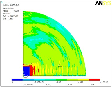
a)
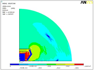
b)
The model helped to identify the acoustic field in the environment of the recuperation device. Fig. 1 shows the impact of the insulating housing on the acoustic field in the installation environment.
3. An experimental study and analysis of the adequacy of the theoretical modeling results
In order to determine the adequacy of the FE model of structural and acoustic field interaction, an experimental study was carried out. It showed the acoustic power of the VSVI 311-4L3 fan and the sound pressure level losses through the insulating housing for each octave band. These primary data were used to conduct a theoretical study of the acoustic field in the installation environment.
3.1. An experimental study of the acoustic field created in the fan environment
This stage aimed to examine the peculiarities of the acoustic field of fixed VSVI 311-4L3 fan and the mechanical system used for its transformation. In order to achieve this, an experiment was carried out to measure the acoustic noise emitted by the fans, their acoustic power, and sound pressure loss through the insulating housing in each octave band under different fan operating modes. The measurement of the acoustic noise emitted by the fans was done by building special equipment which was used to attenuate the noise caused by intake and exhaust airflows. These suppressors of the noise caused by an airflow were made from sound deadening panels. The overall view of the fan and the suppressors is provided in Fig. 2.
Fig. 2The overall view of the equipment used in the experiment: 1 – suppressor on the air intake side; 2 – fan; 3 – suppressor on the air exhaust side
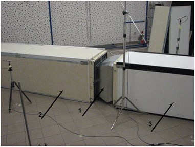
Fig. 3An average sound pressure level in the octave band, depending on the operating mode, when the fan has insulating housing
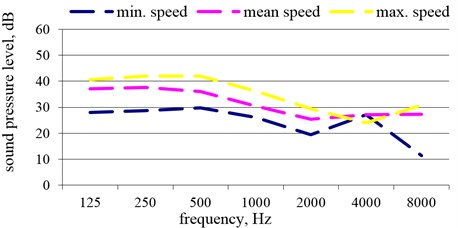
PULSE 3560 acoustic complex of B&K company (Denmark) was used to measure the noise emitted by the fans. For each of the aforementioned experiment conditions, the average and the total weighted sound level and noise source power level values in the entire octave band were determined according to the measured sound pressure values. The results are provided in Fig. 3-4.
Fig. 4The total weighted sound pressure level 1.5 m away from the VSVI 311-4L3 fan
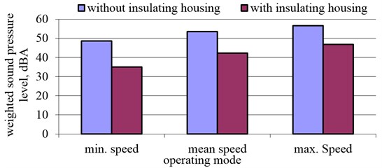
The results indicate that changes to the sound pressure level were noticed at higher frequencies, especially at the 2000-4000 Hz frequency, and that the total weighted sound pressure level emitted by the fan with insulating housing decreased by around 11 dBA under different operating speeds.
3.2. The examination of the adequacy of the theoretical model
The designed acoustic field and heterogeneous mechanical system interaction model was used to examine the environmental noise emitted by the fan. VSVI 311-4L3 fan was used for this study and the sound deadening material was replaced in its insulating housing. The values of the physical and the acoustic characteristics of this material were selected from manufacturer's technical documentation. The experiment also helped to determine sound pressure level losses through the insulating material. All of the data were used for theoretical calculations. The empirical formula for calculating sound pressure level loss (SPLL):
where – wave number in the relevant medium, – wall thickness of the insulating housing, , , – the characteristic impedance of the first, the second, and the third medium respectively.
The model was used to calculate sound pressure level values 1.5 m away from the modified installation under different fan operating modes. The experiment used both experimentally and theoretically determined sound pressure level losses of the insulating material and the results were compared with the experimental ones.
Fig. 5The total sound pressure level under different fan operating modes
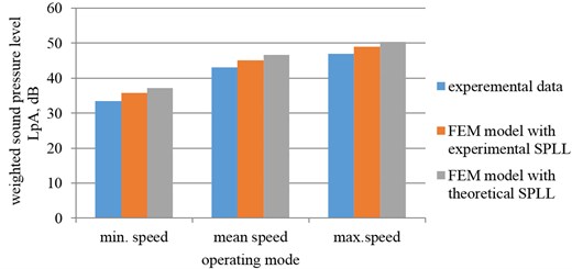
The results show that the total sound pressure level in the installation environment calculated by the designed model closely matched the experimental values. The absolute error of the values calculated by the model by using experimentally determined sound pressure level loss values did not exceed 2.5 dB when compared to the experimental values. Similarly, the absolute error of the values with theoretically calculated sound pressure level losses of the insulating material did not exceed 3.7 dB. This suggests that in order to ensure greater accuracy of the calculations, the theoretical study should be done by using experimentally determined SPLL values.
Where the adequacy of the theoretical model was sufficient, the authors also calculated the expected total sound pressure level of VSVI 311-4L3 fan with replaced insulating material at 1.5 m distance by using theoretically determined SPLL values at 12 mm, 50 mm, and 100 mm thickness levels.
Fig. 6Total sound pressure values calculated by using the FEM model at different insulating material thickness levels and fan operating modes
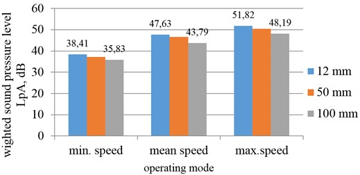
The above results suggest that an increase in the thickness of the insulating material results in the reduction of the total sound pressure level under different operating modes. The produced graphic dependencies allow to quantitatively evaluate changes of the acoustic field in the recuperational installation environment and predict the reduction of noise emissions in the design stage.
4. Conclusions
An acoustic field and heterogeneous mechanical system interaction model was designed. The analysis of its adequacy in terms of the actual processes showed that it can be used to model acoustic field transformation.
The study of fan environmental noise showed that the designed theoretical model allows to predict changes of the acoustic field in the installation environment.
References
-
Shuangli L., Hong N., Caijun X., Xin X. Aeroacoustic testing of the landing gear components. Journal of Vibroengineering, Vol. 14, Issue 1, 2012, p. 205-215.
-
Caijun X., Guang Z., Wei T., Shuangli L. Aeroacoustic noise reduction design of a landing gear structure based on wind tunnel experiment and simulation. Journal of Vibroengineering, Vol. 14, Issue 4, 2012, p. 1591-1600.
-
Ciskowski R. D., Brebbia C. A. Boundary Element Methods in Acoustics. Elseiver Applied Science, New York, 1991.
-
Filippi P., Habault D., Lefevre J. P., Bergassoli A. Acoustics, Basic Physics, Theory and Methods. Academic, New York, 1999.
-
Kludszuweit A. Time iterative boundary element method TIBEM – a new numerical method of four-dimensional system analysis for the calculation of the spatial impulse response. Acustica, Vol. 75, 1991, p. 17-27, (in German).
-
Kopuz S., Lalor N. Analysis of interior acoustic fields using the finite element method and the boundary element method. Applied Acoustic, Vol. 45, 1995, p. 193-210.
-
Yokota T., Sakamoto S., Tachibana H. Sound field simulation method by combining finite difference time domain calculation and multi-channel reproduction technique. Acoustical Science and Technology, Vol. 25, Issue 1, 2004, p. 15-23.
-
Yokota T., Sakamoto S., Tachibana H. Visualization of sound propagation and scattering in rooms. Acoustical Science and Technology, Vol. 23, Issue 1, 2002, p. 40-46.
-
Matsumoto G., Fujiwara K., Omoto A. Directivity of the sound radiated from a factory building. Acoustical Science and Technology, Vol. 22, Issue 6, 2001, p. 434-436.
-
Randall F. B. Industrial Noise Control and Acoustics. Marcel Dekker, New York, 2001.
-
Beranek L. L. Acoustics. Acoustical Society of America, New York, 1996.
-
Wright M. C. Lecture Notes on the Mathematics of the Acoustics. Imperial College Press, London, 2005.
-
Everstine G. C. Finite element formulation of structural acoustics problems. Computers and Structures, Vol. 65, 1997, p. 307-321.
-
Morand H. J.-P., Ohayon R. Fluid Structure Interaction: Applied Numerical Methods. Wiley, Chichester, UK, 1995.
-
Tsingos N., Gascuel J.-D. Soundtracks for computer animation: Sound rendering in dynamic environments with occlusions. Graphics Interface, 1997, p. 9-16.
-
Husung S., Mikalauskas R., Weber Ch., Kästner T. Modelling of sound propagation of technical systems for real-time VR-applications. Mechanika, Vol. 84, Issue 4, p. 33-37.
About this article

This research was funded by the European Social Fund under the project “Microsensors, Microactuators and Controllers for Mechatronic Systems (Go-Smart)” (Agreement No. VP1-3.1-ŠMM-08-K-01-015).
