Abstract
The paper presents research studies in the field of semiactive vibration control of an experimental off-road vehicle which is equipped with suspension magnetorheological (MR) dampers. Accelerometers and vehicle progressive velocity sensors are installed in body and underbody parts of the vehicle and are used in control scheme. Furthermore, IMU modules and suspension deflection sensors were used for validation of measurement part of the system. Semiactive Skyhook control algorithm, including on/off and smooth suspension MR damper control, was implemented in order to validate the control system. Quality of measurements is deteriorated by multiple factors including vehicle engine and shape of tires which was examined. Experimental results indicated better vibration suppression of vehicle body part for smooth Skyhook controller compared with passive soft and hard suspension. The presented semiactive suspension control system can be applied for complex vehicle dynamics analysis and control schemes dedicated to both the ride comfort and ride safety issues.
1. Introduction
Magnetorheological (MR) fluid is one of intelligent materials. Different modes of MR fluid operation can be distinguished, i.e. squeeze mode, shear mode used in MR brakes and flow mode used commonly in MR dampers [1]. Research presented in this paper is focused on application of MR dampers in road vehicles. MR damper can be successfully applied in order to improve both ride comfort and ride safety [2-3]. MR damper which can adaptively change its damping parameters is valued for its low energy-consumption. It is highly desired especially in case of mobile vehicles when available power is limited.
Research was carried out using experimental off-road vehicle ATV Sweden Allroad 500. Original shock-absorbers of the vehicle were replaced with suspension MR dampers produced by Lord Corporation. Semiactive control algorithm implemented in the system can be dedicated to certain suspension models, e.g. quarter-car [4-5], half-car [3] and full-car [6]. The control approach related to quarter-car models is commonly used due to its scalability to more complex multi-damper suspension systems.
Well-known Skyhook semiactive control scheme was introduced for a quarter-car model in [7]. Damping coefficient and consequently force generated by the MR damper can be modulated within the force range limited by dissipative domain [8] which significantly improves quality of vibration control and ride safety in comparison to passive suspension systems.
The paper is organized as follows. Section 2 presents experimental setup, i.e.: off-road vehicle and semiactive measurement and control system. In Section 3 the implemented Skyhook control scheme is referred and additional signal processing procedures are described. Quality of vibration control is reported in Section 4 while achievements presented in the article are summarized in Section 5.
2. Experimental vehicle equipped with suspension measurement and control system
Three parts of presented experiment setup can be distinguished, i.e. (i) an experimental vehicle which is equipped with MR automotive dampers, (ii) vibration control system including sensors and control devices dedicated to MR dampers, (iii) road-induced bump excitation.
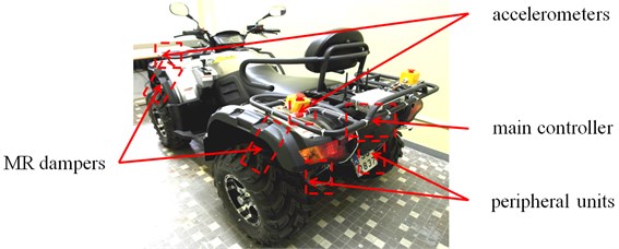
The experimental all-terrain vehicle (2 meters long, 1.2 meter wide and 1 meter high, 340 kilograms of weight) is the key element of the experiment setup (Fig. 1). The vehicle is equipped with different types of Lord’s MR dampers, i.e.: short stroke RD-8041-1 and long stroke RD-8041-1 dampers are installed in the front and rear vehicle part, respectively. Detailed experimental analysis of applied MR dampers reveals similar results obtained for both types of MR damper and maximum axially generated damping force equal to 1.5 kilonewtons [9]. Moreover, it was stated that averaged control currents not greater than 1 ampere are sufficient.
Fig. 1Experimental off-road vehicle and elements of vibration control system
Vertical vibrations of the vehicle are generated using a wooden beam of 90 milimeters height and 2 meters length which is fixed on both ends with concrete blocks.
2.1. Vibration control system installed in the experimental vehicle
The measurement and control system installed in the experimental vehicle is designed according to hierarchical topology; it consists of two layers where the higher layer includes the main controller and the lower layer consists of peripheral measurement and control units, each installed in the vicinity of a wheel (Fig. 2). Elements included in both layers communicate with each other via CAN bus. The main controller is powered by a vehicle battery and communicates wirelessly with a supervisory unit. User of the system implements control algorithms using supervisory unit and, consequently, launches and stops them remotely. Finally, after experiments are finished, results are downloaded to the supervisory unit for further processing.
Fig. 2Topology of the measurement and control system installed in the experimental vehicle
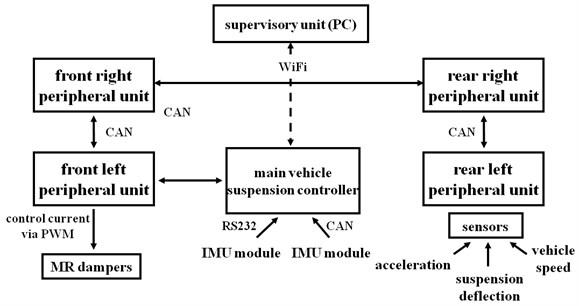
Numerous sensors are installed in the vehicle: 8 accelerometers located in the vicinity of each wheel in the vehicle body and underbody part, Hall effect sensors which measure progressive velocity of each wheel, optical distance sensors which measure suspension deflection of each suspension part and additional IMU modules installed close to wheels and driver’s seat connected directly via CAN bus or RS232 to the main controller. Peripheral units are responsible for taking measurements with desired sample rate, in most cases it is 400 Hz for accelerometers and 100 Hz for other sensors.
Each MR damper is controlled using dedicated peripheral unit via PWM voltage signal of the amplitude equal to 12 volts. Measurements of averaged current supplying each MR damper are used for current stabilization and online validation of MR damper control. The current controller is implemented in the peripheral unit which decreases amount of data transferred via CAN bus. The current control algorithm consists of a nonlinear static inverse controller which is based on nonlinear relationship estimated between the voltage signal duty cycle and the resultant averaged control current. The control signal generated by the static controller is corrected using an additional PI controller with gain scheduling.
2.2. Sources of measurement noise
Measurement data, especially acceleration measurements are significantly deteriorated by vibrations of other vehicle components. Vehicle engine and vehicle tires are the main sources of measurement noise. The experimental vehicle is equipped with four-stroke petrol engine including one cylinder. An ignition of fuel-air mixture occurs every second engine revolution. Thus, vibrations which are induced by the vehicle engine and propagate through the vehicle construction are directly related to the vehicle engine speed and indirectly to the vehicle progressive speed. Moreover, level of engine-induced vibrations is high, comparable to the level of road-induced vibrations as well as significantly nonlinear which results in multiple harmonics generated for higher frequency range.
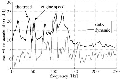
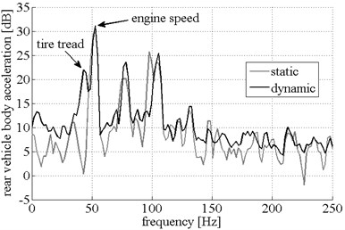
During the system validation phase, two experiments were performed; the former for not moving vehicle and the latter for moving vehicle and no road bump excitation. Such approach allows for isolating the tire- and engine-induced disturbance signals. In case of not moving vehicle first harmonics of the engine-induced disturbance is noticeable at 50 Hz (3000 revolutions per minute of engine speed) in frequency characteristics (Fig. 3). Moreover, further harmonics up to the third are detectable as well which confirms the need of oversampling acceleration signals.
Fig. 3acceleration measurement data: rear vehicle wheel and body part
a)
b)
Second experiment was performed while the vehicle was driven with constant progressive velocity of 12 kilometers per hour (measured using Hall effect sensors) and corresponding engine speed the same as in case of previously presented static experiment. Both frequency characteristics are presented in Fig. 3. overlapping each other in order to clearly distinguish both sources of additional vibrations. The additional frequency peak occurs for frequency equal to 41 Hz. Further studies indicated that this frequency value is directly proportional to vehicle progressive speed. It was stated that the road-induced disturbance frequency equal to 41Hz is a 20th multiplication of the wheel rotational frequency, which relates this disturbance to vehicle tires, strictly their thick tread.
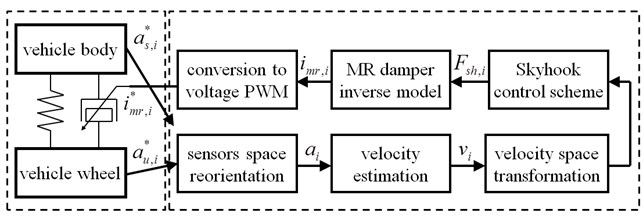
3. Semiactive vehicle vibration control scheme
The Skyhook control scheme was applied according to the one presented by Karnopp [8]. The control scheme was executed independently for each quarter of the vehicle as presented in Fig. 4. The following operational blocks can be distinguished: acceleration space reorientation, velocity estimation, velocity space transformation, general Skyhook algorithm, inverse MR damper model and control current limitation. Different orientation of the accelerometers requires the axis to be reoriented according to the vehicle's reference coordinate system. Furthermore, velocity signals are estimated based on acceleration measurements and consequently they are transformed in space in order to fit the bending angle of suspension MR dampers.
Fig. 4Control block diagram of semiactive vibration control scheme dedicated to each quarter of the vehicle suspension
3.1. Skyhook control dedicated to quarter-car model
Force desired by the Skyhook algorithm to be generated by each MR damper is defined as follows:
where index denotes selected quarter of the vehicle in the front and rear as well as the right and left part whereas denotes the vertical velocity of selected vehicle body quarter. The parameter of the Skyhook related to the selected quarter of vehicle is denoted as and varies from 3000 to 7000. According to the Skyhook algorithm, force defined in Eq. (1) is activated if the following relation is met:
where denotes the relative velocity of the suspension deflection of selected vehicle part.
Velocity signals are estimated based on acceleration measurements. Initially, an offset value generated by the gravitational field is filtered out from measurement data. Consequently, the velocities for all vehicle body and underbody parts are estimated using the first order integration as follows:
where denotes an acceleration measurement signal.
Two approaches to control the MR damper can be distinguished, i.e. smooth control and on-off control. The on-off control is favored for its simplicity and no need of MR damper inverse model evaluation. However, quality of the on-off control approach is always deteriorated in comparison to the smooth control scheme. The Skyhook algorithm was implemented and validated for those two cases.
3.2. Inverse model of the MR damper
The current controlling the MR damper is calculated using the inverse model of the damper. The MR damper reveals strongly nonlinear behavior including hysteresis loops and saturation regions visible in the force-velocity characteristics. Numerous models have been presented in the literature [10]. However, a compromise should be met since such models need to be not only accurate but also applicable in real-time. Thus, the structure is simplified and the number of parameters is limited resulting in the model presented in [9] as follows:
where –23, 1215, 36, 1203. Axial velocity of the MR damper is denoted by and control current for MR damper is denoted as .
The inverse model can be obtained after reformulation of Eq. (4) resulting in the following:
which is applied in the presented control algorithm.
4. Experimental results
Different experiment scenarios were examined which differ in types of control algorithms and their parameters, i.e.: passive soft and hard (average current equal to 0.2 A) suspension system, Skyhook control with on/off and smooth MR damper control. The smooth Skyhook control was evaluated for parameters varying from 3000 to 7000. In case of the on/off Skyhook control two scenarios were tested, i.e. for maximum average current equal to 0.1 and 0.2 A. Each experimental case was tested at least 7 times using single-bump vehicle ride. Similarity between consecutive time diagrams was validated and incorrect experiment results were excluded from the final data set. The resultant time diagrams were evaluated by averaging at least 5 selected time diagrams.
Acquisition of acceleration data was performed with sample rate equal to 400 Hz, measurements from other sensors were sampled with 100 Hz. For the purpose of vibration control validation, acceleration data are processed using highpass filters and finally integrated and synchronized over the consecutive experiments.
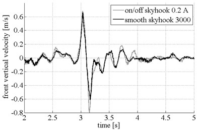
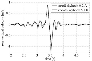
The analysis is focused on velocity signals obtained for the front and rear vehicle body part. Different cases of on/off and smooth Skyhook control algorithms were compared and the most advantageous were chosen which is presented in Fig. 5. It was stated that in case of the front suspension part best results are obtained for on/off Skyhook control for maximum current equal to 0.2 ampere and smooth Skyhook control with parameter equal to 3000. In case of the rear suspension part smooth Skyhook control with parameter equal to 5000 gives slightly better results; thus, such case was selected for comparison. In both front and rear cases smooth Skyhook control gives much better results than on/off control which reveals in smaller negative amplitude of vertical velocity while the vehicle rides with the obstacle.
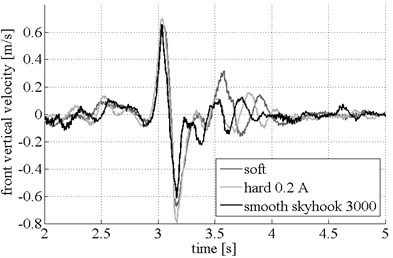
Furthermore, results obtained for semiactive vibration control were compared with those obtained for soft and hard passive suspension and are presented in Fig. 6. It can be stated that high vibration suppression during the first two shocks is an advantage of the soft suspension. However, such suspension is burdened with a long-decay time response after the bump obstacle is traversed. The hard suspension exhibits higher frequency response. However, contrary to the soft suspension, shocks suppression of the hard suspension is significantly deteriorated. Finally, the Skyhook control for the front and rear vehicle part is recommended; it not only exhibits a good shock suppression but it also gives a shorter decay time after the obstacle is traversed.
Fig. 5Vertical velocity for on/off and smooth Skyhook control schemes: front and rear vehicle body velocity
a)
b)
Fig. 6Vertical velocity for passive soft, passive hard and smooth-Skyhook control schemes: front and rear vehicle body velocity
a)
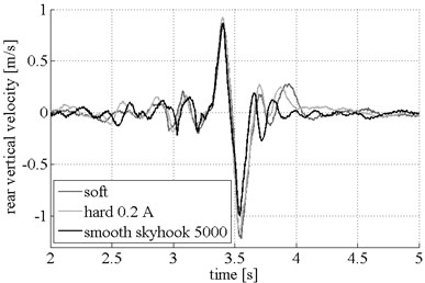
b)
5. Conclusions
Dynamics of the experimental vehicle, equipped with semiactive vibration control system and subjected to road bump excitation, was examined. Measurement data obtained during the road experiments were deteriorated by multiple disturbances including high power vibrations induced by the engine and vibrations generated by tires and other vehicle devices.
Validation of the semiactive suspension control was carried out using well-known Skyhook algorithm. Two approaches of MR damper control were tested, i.e. on/off and smooth control approach. Results obtained for semiactive algorithms were compared to those obtained for the passive soft and hard suspensions. Responses of the vehicle to bump excitation were compared in time domain that shows significantly better vibration control of the implemented Skyhook control in comparison to passive suspension.
The semiactive suspension control system is to be used for implementation of the more complex control schemes dedicated to multi-DOFs models. Moreover, the implemented control schemes will be related to comfort and safety issues as well as additional adaptive procedures.
References
-
Sapiński B. Magnetorheological Dampers in Vibration Control. AGH University of Science and Technology Press, Cracow, Poland, 2006.
-
Dong X. M., Yu M., Li Z., Liao C., Chen W. A comparison of suitable control methods for full vehicle with four MR dampers, part I: Formulation of control schemes and numerical simulation. Journal of Intelligent Material Systems and Structures, Vol. 20, 2009, p. 771-786.
-
Krauze P. Comparison of control strategies in a semi-active suspension system of the experimental ATV. Journal of Low Frequency Noise, Vibration and Active Control, Vol. 32, Issue 1-2, 2013, p. 67-80.
-
Kasprzyk J., Krauze P. Semi-active vibration control with on-line identification of the inverse MR damper model. 21st International Congress on Sound and Vibration ICSV21, Beijing, China, 2014.
-
Krauze P., Kasprzyk J. Neural network based LQ control of a semiactive quarter-car model. 18th IEEE International Conference on Methods and Models in Automation and Robotics, Poland, 2013.
-
Hrovat D. Survey of advanced suspension developments and related optimal control applications. Automatica, Vol. 33, 1997, p. 1781-1817.
-
Karnopp D., Crosby M. J., Harwood R. A. Vibration control using semi-active force generators. Journal of Engineering for Industry, Vol. 96, 1974, p. 619-626.
-
Savaresi S. M., Poussot-Vassal C., Spelta C., Sename O., Dugard L. Semi-active suspension control design for vehicles. Butterworth-Heinemann, Elsevier, 2010.
-
Kasprzyk J., Wyrwał J., Krauze P. On some aspects of automotive MR damper modeling for semi-active suspension. International Conference on Advanced Intelligent Mechatronics, France, 2014.
-
Spencer B. F., Dyke S. J., Sain M. K., Carlson J. D. Phenomenological model of a magnetorheological damper. ASCE Journal of Engineering Mechanics, Vol. 123, 1997, p. 230-238.
About this article

The work reported in this paper has been partially financed by the National Science Centre, decision No. DEC-2011/01/B/ST7/06027.
