Abstract
An adaptive neural network (ANN) control method for a continuous damping control (CDC) damper is used in vehicle suspension systems. The control objective is to suppress positional oscillation of the sprung mass in the presence of road irregularities. To achieve this, a boundary model is first applied to depict dynamic characteristics of the CDC damper based on experimental data. To overcome nonlinearity issues of the model system and uncertainties in the suspension parameters, an adaptive radial basis function neural network (RBFNN) with online learning capability is utilized to approximate unknown dynamics, without the need for prior information related to the suspension system. In addition, particle swarm optimization (PSO) technique is adopted to determine and optimize the parameters of the controller. Closed loop stability and asymptotic convergence performance are guaranteed based on Lyapunov stability theory. Finally, simulation results demonstrate that the proposed controller can effectively regulate the chassis vertical position under different road excitations. Furthermore, the control performance is determined to be better than that of the typical Skyhook controller.
1. Introduction
Suspension systems are among the most critical components that ensure ride comfort along with good road handing and safety in ground vehicles. A vehicle is always subjected to random excitation due to an irregular road profile. Vehicle suspension systems are designed to absorb the energy and mitigate uncomfortable vibrations due to this random excitation. These suspension systems can be broadly classified into three categories based on their energy consumption: passive, active and semi-active suspension systems. In the case of passive suspension systems, parameters cannot be changed once fixed [1]. Thus, active and semi-active suspension systems are the current focus of extensive research for creating adaptive suspensions to improve vehicle ride comfort and road handing [2]. In active suspension systems, separate actuators are used to effectively regulate motion of the vehicle body over a wide frequency spectrum. Unfortunately, the high cost and complexity of such a system limit its commercial applications. Ride comfort with semi-active suspension is comparatively lower compared to their active counterparts. However, performance benefits in semi-active systems exceed those of passive systems without the need for large power supplies and expensive hardware as in the case of active systems [3]. Furthermore, if semi-active suspension fails for any reason, the system functions as a passive system and remains stable.
A variety of dampers can be used to generate damping force in vehicle suspensions. However, for semi-active vehicle suspensions, CDC dampers and magneto-rheological (MR) fluid dampers are mostly utilized as the controllable shock absorbers [4]. A CDC damper varies the size of an orifice in the hydraulic flow valve, which can give continuously variable damping characteristics [5]. On the other hand, the MR damper uses magnetic fields to vary viscosities of the MR fluid, and electro-rheological fluids exhibit rheological changes when an electric field is applied to the fluid [6-8]. Compared with magneto-rheological and electro-rheological dampers, the CDC damper is much simpler in design and less expensive. It also has the advantage of reliability and durability. The CDC damper made by ZF SACHS has been successfully applied in commercial vehicles such as VW-Phaeton, Ford-Mondeo, GM-Lacrosse. Several models are discussed in this paper to characterize the performance of semi-active dampers in terms of their dynamic behavior. Generally, the dynamic models for CDC dampers can be broadly categorized as parametric and nonparametric models. The Bouc-Wen hysteresis model [9] and NARX model [10] are parametric models, whereas, the neural network model [11] and fuzzy model [12] are nonparametric models. Briefly, parametric models can be identified based on their use of mechanical elements, which are tested using experimental studies [13]. Non-parametric models use mathematical methods, which are not correlated to any physical elements. In this paper, constraints for output forces using a CDC damper are described. Upper and lower bounds are introduced to restrict desired forces in the controller design.
CDC dampers, used as the actuators in semi-active suspension systems require proper control. Thus, an increasing number of researches reported in literature have focused on control of semi-active suspension systems. A wide array of methods has proposed ranging from a simple on-off control technique to advanced techniques for linear and nonlinear control, such as LQG/Hcontrol [14], LPV control [15], backstepping control [16] and quantitative feedback theory [17]. The Skyhook control strategy, first proposed by Karnopp [18], is a classical semi-active control approach, which has been demonstrated to be effective in reducing vertical oscillations of the chassis. Since then, a number of modified Skyhook control methods [19-21] have been developed. Groundhook [22] and hybrid control approaches [23] resolve issues due to unsprung mass vibrations, thereby achieving better road holding ability and improving vehicle stability. In a previous study [24], a sliding mode control has been proposed to design a sliding surface, which included sprung mass acceleration and tire deflection. Energy-Flow-Driven [25] has been proposed as a control method, which allows energy transfer between the vehicle chassis and tire. Recently, some studies have attempted to combine road estimation and semi-active suspension system to provide better controller and observer performance [26, 27]. Typically, most control algorithms aim at evaluating trade-off of semi-active control laws in terms of ride comfort and road holding. Moreover, with the recent trend of self-driving ground vehicles, which are equipped with mounted cameras, vertical vibration amplitude of the camera needs to be reduced to remove unwanted motion from dynamic camera sequences. Therefore, in this paper, larger emphasis is on vertical body displacement when evaluating performance indices of suspension systems in unmanned or self-driving ground vehicles.
Recently, intelligence control algorithms based on fuzzy logic control and neural network control have been proposed. Establishing reasonable fuzzy rules is one of the challenging aspects in the design of a fuzzy controller. The number of fuzzy rules and parameters for membership functions is determined automatically using genetic algorithm operations [28]. The controller design methodology used in previous works did not need accurate models of the suspension system. Conversely, neural networks have received increasing attention, with application in a number of research fields [29, 30]. This is mainly due to the advantages associated with approximating uncertain nonlinear functions in a dynamic system. In a previous study [31], a neural networks control for semi-active suspension system has been described, which includes an error back propagation algorithm with quadratic momentum of the multilayer forward neural networks. A neural networks scheme employed an adaptive tuning law to control a bus suspension system [32]. A semi-active suspension with the CDC damper is a nonlinear dynamic system, thus traditional control strategies based on mathematical models with random road roughness cannot be easily applied. This is due to it is difficulty in obtaining accurate models of vehicle suspension for practical applications. An adaptive neural network control can be used in this case as prior system information is not required. This is a promising approach that can guarantee good performance of semi-active suspension systems.
In this paper, an adaptive neural network control of a quarter-car model of a semi-active suspension with the CDC damper is developed. The main objective of the algorithm is to suppress vertical oscillation amplitude of the sprung mass in the presence of road irregularities. For this purpose, a boundary model with nine straight envelope lines is proposed to depict dynamic characteristics of the CDC damper based on the experimental data. Next, an adaptive RBFNN is designed to deal with unknown nonlinear dynamics of the semi-active suspension system. RBFNN can approximate any continuous function to any desired accuracy with proper weights of neural networks. Also, the weights of the RBFNN can be adaptively adjusted online. It could improve the robustness of the closed-loop system. PSO technique is used to optimize parameters of the control law according to the overall performance indices. Finally, effectiveness of the proposed control approach is validated by three typical road excitations, and performance of ANN control is compared with the typical Skyhook control and the passive suspension case in the simulations.
The remainder of this paper is organized as follows. In Section 2, the dynamic model of a semi-active suspension system with nonlinear stiffness and the friction is described. In Section 3, the detailed design procedure of the boundary model of CDC damper is given. Section 4 develops the adaptive neural network controller and describes the PSO algorithm to obtain the control design parameters. The results of computer simulations of the controller are presented in Section 5. Finally, Section 6 summarizes the results and presents the conclusions of this work.
2. Nonlinear semi-active suspension system
A quarter-car semi-active suspension model with two degrees of freedom (2-DOF) is shown in Fig. 1. The term represents the sprung mass of the car body. While the unsprung mass is given by . Variables , and represent the absolute displacement of the body, wheel profile and road profile, respectively. The tire is modeled as a linear spring with stiffness . Suspension damping coefficient is manipulated as a variable of the control system. The polynomial nonlinear stiffness model of suspension system [33] is given as:
Fig. 1Quarter-car model with the semi-active suspension
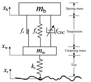
Here, suspension nonlinearities including stiffness and the friction force are taken into consideration. Friction force occurs between the damper’s piston and cylinder. Dynamic friction force is defined as , and represents critical velocity when the static friction becomes the dynamic friction. Friction force can be described by the below equation [34]:
Nonlinear dynamic equations of the suspension system can be expressed as:
where is a function of the relative velocity and current input. Sprung mass dynamics can be simplified as:
where is an unknown bounded function and is the uncertain parameter, which is easily varied according to the vehicle load. From Eq. (3), the unknown bounded function can be given as:
In a vehicle system, nonlinearity of suspension model and uncertainties in suspension system affect the vibration mitigation performance. For example, properties of the damper vary with time due to the heating of the fluid. Influence of uncertainties should be taken into account in the design of the controller.
To facilitate the design of proper control schemes, the following assumption and lemma are used throughout the paper.
Assumption: Road profile disturbance is bounded.
Lemma [35]: Let be a continuous function, which is defined over a compact set . Then, there exists a neural networks system which can approximate with arbitrary accuracy, such that:
where is the ideal constant weight vector, is the RBFs vector, is the number of neurons, is approximation error which is minimized by the ideal vector :
Assuming is bounded, with being an unknown constant. is a Gaussian function as described below:
With is the center of the receptive field and is the width of the Gaussian function.
3. Boundary CDC damper model
In this work, the CDC damper has a solenoid valve inside, which is used to generate damping force. The direction of the damping force is opposite to the direction of relative velocity of the suspension, and it can only produce forces in the first and third quadrants in the force-velocity graph. In other words, force distribution in the force-velocity graph is the intrinsic passivity constraint due to characteristics of CDC dampers. Since, this research focuses on the overall performance evaluation of control strategy for semi-active suspension systems, the hysteresis effect is not taken into consideration and only peak damping forces at individual peak velocities in the velocity-force map are recorded. In this case, the boundary model is obtained from experimental data.
A photograph of the structure containing CDC damper and coil spring is shown in Fig. 2. The working characteristics of the CDC damper are tested on a MTS load frame. Force and displacement are measured using a load cell and LVDT sensor. Relative velocities are calculated using the central difference method [36, 37]. When the control algorithm is applied, the suspension system state (relative velocity) can be obtained by a variety of observers, such as the high gain observer [38] and higher order sliding mode observer [39]. Sinusoidal excitations with amplitude of 50 mm, and calculated frequencies of 0.17 Hz, 0.41 Hz, 0.83 Hz, 1.24 Hz, 1.72 Hz, 2.45 Hz, 3.31 Hz and 4.77 Hz are applied. The resulting peak velocities are 0.052 m/s, 0.13 m/s, 0.26 m/s, 0.39 m/s, 0.54 m/s, 0.77 m/s, 1.04 m/s and 1.5 m/s for each of the frequencies respectively. Control current is varied from 0 A to 1.8 A at internals of 0.2 A. The velocity-force map for the adopted CDC damper is shown in Fig. 3.
Fig. 2Photograph of CDC damper and MTS load frame
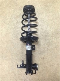
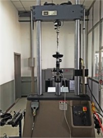
Fig. 3Velocity-force map of CDC damper
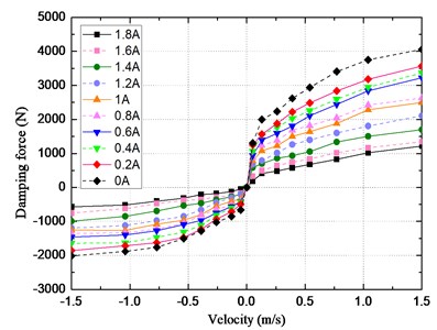
Damping force increases with increase in the relative velocity. However, it can be seen that slope is steeper as the current input decreases. Damping force is determined by the input current and the input velocity to the CDC damper. This means that there are upper and lower bounds on the force. The boundary model primarily focuses on the maximum and minimum output force of CDC damper for each value of . Boundary force corresponding to the control currents of 0 A and 1.8 A can be fitted piece-wise into nine straight lines, such as:
The boundary area and the nine lines of the adopted CDC damper are shown in Fig. 4. The parameters for each of these nine lines are estimated by the least squares method and tabulated in Table 1.
Fig. 4Boundary model of CDC damper
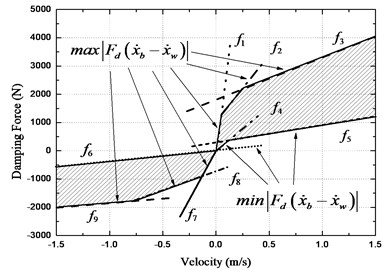
Table 1Parameters of boundary damper model
25154 | 0 | 4447 | 1077 | 1473 | 1850 | 3181 | 0 | 587 | 337 | |
381 | 0 | 6592 | 0 | 1409 | –674 | 351 | –1489 | |||
4. Control system
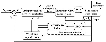
The adaptive neural network controller generates a desired damping force according to the control law. In order to improve the performance of the semi-active suspension system, PSO method is used to select parameters of the controller and weighting update laws. Since, the semi-active damper has upper and lower bounds on the force. The actual force is calculated using the boundary CDC damper model based on the derivative of suspension deflection. Desired value of the body displacement is set as zero. Then, the CDC damper produces the actual damping force for the quarter car model of vehicle suspension. The structure diagram of the semi-active controller for vehicle suspension is depicted in Fig. 5.
Fig. 5Structure diagram of the semi-active controller for vehicle suspension
4.1. Adaptive neural network full state feedback controller design
A generalized tracking error is used here which is defined as , where is a reference trajectory, as well as an auxiliary error vector which is given as:
The derivative with respect to time is given as:
Using Eq. (11), the subsystem dynamic Eq. (5) can rewritten as:
However, semi-active suspension systems are complicated by nonlinearities and uncertainties in the system dynamic. In this case, both and may not be known exactly. Radial basis function neural network (RBFNN) is used to approximate parameters in the dynamic model, according to the Lemma, and can be written as:
Substituting Eq. (13) into Eq. (12):
Now, we propose the following control as:
where, is the estimation of the unknown vector :
The RBFNN updating law is defined as:
where, , , , , are chosen by design, and is the matrix related to adaption rate, and is the unknown bounded value. A robust term is designed as to overcome the effects caused by approximation error.
The adaptive neural network control development can be summarized in the following theorem.
Theorem: Considering semi-active suspension system (3-4) satisfies the assumption, with the lemma and control input Eq. (15) is governed by the adaptive laws Eqs. (17) and (18), given that the full state information is available. For bounded initial conditions, , and in closed loop system are uniformly ultimately bounded (UUB).
Proof:
Considering the effect of error and into the system’s stability, a Lyapunov function candidate can be proposed as:
Taking derivative of with respect to time, the following expression is obtained:
A closed loop system is obtained by integrating the control law Eq. (15) into Eq. (14):
Substituting Eq. (21) into Eq. (20):
With the updated laws stated in Eq. (16) and Eq. (17), it follows that:
To guarantee closed loop stability, Lyapunov function candidate should be negative. Therefore, the following expression is satisfied:
It can be rewritten as:
Then, the derivative of the Lyapunov function becomes:
Inequality Eq. (26) shows that and are bounded as . The proof has been finished.
4.2. Particle swarm optimization
The ANN controller performance discussed in the preceding section is mainly influenced by the following control parameters: , , , , and . Consequently, PSO is widely used for optimizing the controller parameters and is believed to perform better than the ‘trial and error’ method [40-42]. This method is a random optimization method based on swarm intelligence. Control parameters in this method are referred to as the particles, each with their own position and velocity. Starting with a random initialization, particles efficiently search a space to minimize an objective function which is also called the fitness function. The operation of the PSO in the th iteration is described by the following equations [43]:
where, is the position of the particle, is the present particle velocity, is the inertia weight, and are uniform random numbers in the range of [0 1], and are acceleration coefficients, namely cognitive and social scaling parameters. is the group-best (global) solution found up to the current iteration and is the personal-best solution found by individual particles from their search history.
In many applications, a larger inertia weight is favorable for global search, and a smaller inertia weight is suitable for local search. To balance the ability between the global and the local search, is proposed [44] as:
where, is the maximum number of iteration, and have the typical values of , .
The objective function for PSO includes different performance criteria, such as root-mean-square (RMS) value of the vehicle body displacement, suspension deflection, tire deflection and sprung mass acceleration. It can be shown as:
where, , , and are terms which act as weights for the different system outputs. In the case of self-driving or unmanned vehicles, vehicle body position stabilization in vertical direction is more important than ride comfort. Thus, for this study values for the weights are selected as 10, and Smaller value of implies better overall performance of the vehicle suspension.
5. Simulations
To evaluate the efficacy of the proposed control strategy, numerical simulations are performed for the quarter-car model equipped with CDC damper. The CDC damper used in the experiments is manufactured by ZF Sachs Company, which develops and produces damper and suspension strut modules. The suspension deflection should not exceed the limit of CDC damper working spaces, as it could damage the suspension components when the mechanical displacement restrictor is working. In this paper, value of the rattle space constraint is set as 120 mm. The parameters of the vehicle suspension are listed in Table 2.
Table 2Parameter values of the semi-active suspension system
Parameter | Description | Value |
Sprung mass | 410 kg | |
Unsprung mass | 39 kg | |
Linear suspension stiffness | 16812 N/m | |
Nonlinear suspension stiffness | –73696 N/m2 | |
Nonlinear suspension stiffness | 3170400 N/m3 | |
Tire stiffness | 190000 N/m | |
Passive system damping | 1100 N/m/s | |
Critical velocity | 0.01 m/s | |
The dynamic friction | 30 N |
The initial condition of the system is set as , and the number of neurons in the hidden layer are 16. Initial weighting vectors are selected as and the center of Gaussian function is set as and ( 1, 2, 3,…, 16). The final parameter values optimized by PSO for the design controller in three typical cases are listed in Table 3.
Table 3Controller parameters of the ANN
Parameter | ||||||
Case 1 | 872.5 | 3.1 | 0.097 | 0.052 | 3.5 | 137 |
Case 2 | 1353 | 2.7 | 0.13 | 0.037 | 0.01 | 215 |
Case 3 | 2057 | 1.2 | 0.1 | 0.015 | 0.017 | 306 |
In simulations, a classical semi-active control approach known as the Skyhook controller is adopted for comparing and validating the performance of the designed controller. The continuous Skyhook controller defines the desired damping force as:
where, is the Skyhook damping force and is the Skyhook gain. The Skyhook control gain selection is important for the controller comparison. Here, the gain is selected as 3000 Ns/m by weighting 0.5 to 0.5 for ride comfort and road handling. Also, readers could use the continuously variable skyhook control as a contrast algorithm.
5.1. Model of road profiles and road roughness
To evaluate the performance of the designed controller, three typical cases are considered.
Case 1: As resonance frequency of the car body is about 1 Hz [45-46], an external excitation close to this frequency may induce unwanted oscillation. Then, to verify control performance near the system resonance frequency, the road profile is defined as:
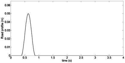
Case 2: Consider a sinusoidal bump in an otherwise smooth road surface. Mathematical description of this type of ground displacement is given by:
where, and are height and length of the bump, and is the vehicle velocity. Suppose, 0.5 m, 2.5 m and 20 km/h. The corresponding road excitation is shown in Fig. 6.
Fig. 6Bump road profile
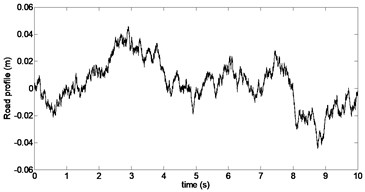
Case 3: Consider road excitation which is consistent and typically specified as a random process with a ground displacement power spectral density (PSD) given by:
where, is the spatial frequency in , stands for PSD in time domain, and is the reference spatial frequency. Road roughness is given as , 0.1, 2 and 40 km/h. This PSD indicates that the road profile can be obtained by integrating white noise in time domain [47]. The resulting displacement of the road excitation in time domain is shown in Fig. 7.
Fig. 7Random road profile
5.2. Comparison of controller performance
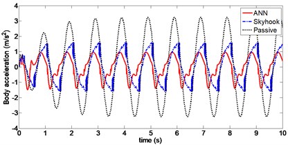
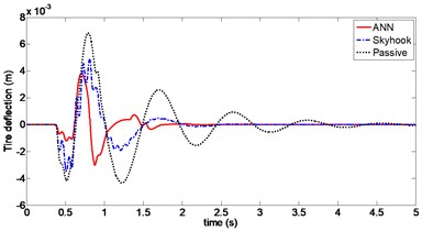
The closed-loop system responses for the sinusoidal road excitation are plotted in Fig. 8 to 10, which show vehicle body displacement, body acceleration and tire deflection, respectively. It can be clearly seen that body displacement and body acceleration have relatively lower magnitude with ANN control compared to Skyhook control. Numerically, the RMS value of the body displacement is 0.021 with ANN control and 0.025 with Skyhook control. In the case of the former, the RMS decreases by 61 % compared to passive suspension systems. ANN control can suppress 66 % RMS value of sprung acceleration, which is an improvement of 54 % compared to Skyhook control. The peak-to-peak value of tire deflection with proposed ANN control is 5.9 mm, which is smaller than the 6.7 mm obtained using Skyhook control. Thus, ANN control with CDC damper improves performance over Skyhook control.
Fig. 8Body displacement (Case 1)
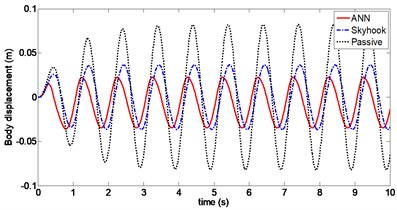
Fig. 9Body acceleration (Case 1)
For a vehicle crossing a bumpy terrain, dynamic responses of the sprung mass position, body acceleration and tire deflection using ANN and Skyhook control are shown in Figs. 11 to 13. It can be observed that the amplitudes of body displacement and sprung mass acceleration diminish much faster for both ANN and Skyhook control compared to passive suspension. Maximum value of body displacement is 29 mm with ANN control, which is significantly lower than 46 mm with Skyhook control. Peak-to-peak value of the tire deflection is reduced from 8.2 mm to 6.8 mm compared to Skyhook control. Damping forces produced by CDC damper for both controllers are compared in Fig. 12. In particular, chattering with Skyhook controller causes undesirable switching for force outputs, which may affect body acceleration when crossing a bump in the road. This effect can be seen at around 0.6 s.
Fig. 10Tire deflection (Case 1)
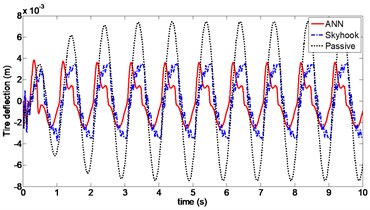
Fig. 11Body displacement (Case 2)
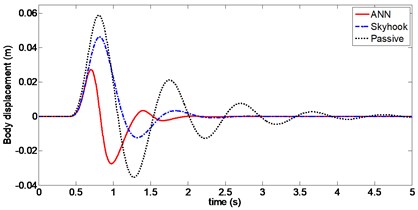
Fig. 12Body acceleration (Case 2)
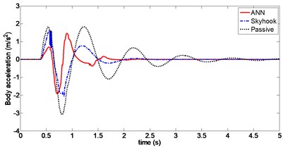
Fig. 13Tire deflection (Case 2)
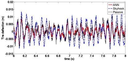
Dynamic response of the sprung mass displacement with random excitation is shown in Fig. 14. For Skyhook control, the RMS value is 0.0182, whereas in the case of ANN control, it is equal to 0.01. Sprung mass stability is significantly improved using ANN control with RMS decreasing to approximately 47 %. Peak value of the vertical body displacement is 41 mm using Skyhook control and is only 31 mm with ANN control. The curve between 6 second and 8 second dynamic response of the tire deflection is shown in Fig. 15, the RMS value of tire deflection with ANN control is 0.0032, which is slightly smaller than a value of 0.0035 obtained using Skyhook control. However it can be seen that the value of tire deflection with Skyhook control has deteriorated compared to that of the passive suspension. Frequency domain analysis of the PSD curves of the vehicle body acceleration is shown in Fig. 16. From the figure, it can be seen that PSD of ANN is considerably lower compared to Skyhook in the body resonance frequency range (1-1.5 Hz).
Fig. 14Body displacement (Case 3)
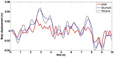
Fig. 15Tire deflection (Case 3)
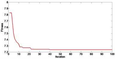
Optimal control design parameters can be obtained using the proposed PSO algorithm, which allows for significant improvement in the performance of semi-active vehicle suspension. Parameters for PSO algorithm in case 3 are set as 1.5 and 1.5. In Fig. 17, it can be seen that the fitness function converges after 40 iterations.
The further simulations with senor noise are presented to demonstrate that ANN control scheme can withstand the additive noise. Sensor noise was added to the measured suspension stroke and performance is evaluated [48]. The performance of sprung mass displacement, sprung mass acceleration and tire deflection for random road excitation has been presented in Table 4.
Fig. 16PSD of vehicle body acceleration (Case 3)
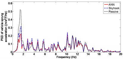
Fig. 17Convergence of fitness function (Case 3)
Based on the proposed method, further researches can be made with combination of road estimation and form road adaptive ANN semi-active suspension system for further improvement under varying road conditions. For road estimation methods, [49] can be used to guideline for controller parameters tuning.
Table 4Performance evaluation over senor noise
Senor Noise RMS | Sprung mass displacement RMS (m) | Sprung mass acceleration RMS (m/s2) | Tire deflection RMS (mm) |
1.1×10⁻⁵ | 0.012 | 0.92 | 3.38 |
3.3×10⁻⁵ | 0.014 | 0.98 | 3.32 |
6. Conclusions
In this paper, an adaptive neural network controller for a nonlinear suspension system using a CDC damper is proposed. A semi-active control design is considered using a boundary model of the CDC damper. The boundary model is constructed piece-wise using nine straight lines based on the experimental data. The adaptive controller is designed to meet control objectives and RBFNN is used to approximate the nonlinear uncertain part of the suspension system. Moreover, parameters for control law are optimized using PSO. The closed loop stability along with asymptotic convergence performance are proved using Lyapunov theory. Finally, the performance of this controller is validated by numerical simulations under three different road conditions. Improvement in RMS values is achieved using the proposed controller and values for body displacement are lower compared to Skyhook controller. These results validate the efficacy of the proposed controller to achieve better performance for semi-active suspension systems in comparison to both Skyhook control and passive suspension systems.
References
-
Hrovat D. Survey of advanced suspension developments and related optimal control applications. Automatica, Vol. 33, Issue 10, 1997, p. 1781-1817.
-
Zong L. H., Gong X. L., Guo C. Y., et al. Inverse neuro-fuzzy MR damper model and its application in vibration control of vehicle suspension system. Vehicle System Dynamics, Vol. 50, Issue 7, 2012, p. 1025-1041.
-
Ren H., Zhao Y., Chen S., et al. State observer based adaptive sliding mode control for semi-active suspension systems. Journal of Vibroengineering, Vol. 17, Issue 3, 2015, p. 1464-1475.
-
Tseng H. E., Hrovat D. State of the art survey: active and semi-active suspension control. Vehicle System Dynamics, Vol. 53, Issue 7, 2015, p. 1034-1062.
-
Choi J. Y. High tunable control algorithm for semi-active suspension by a normal type CDC damper. Journal of Institute of Control, Robotics and Systems, Vol. 16, Issue 11, 2010, p. 1096-1103.
-
Du H., Lam J., Zhang N. Modelling of a magneto-rheological damper by evolving radial basis function networks. Engineering Applications of Artificial Intelligence, Vol. 19, Issue 8, 2006, p. 869-881.
-
Yao G. Z., Yap F. F., Chen G., et al. MR damper and its application for semi-active control of vehicle suspension system. Mechatronics, Vol. 12, Issue 7, 2002, p. 963-973.
-
Qin Yechen, Dong Mingming, Zhao Feng, et al. Comprehensive analysis influence of controllable damper time delay on semi-active suspension control strategies. Journal of Vibration and Acoustics-Transactions of ASME, https://doi.org/10.1115/1.4035700.
-
Choi S. B., Lee S. K., Park Y. P. A hysteresis model for the field-dependent damping force of a magnetorheological damper. Journal of Sound and Vibration, Vol. 245, Issue 2, 2001, p. 375-383.
-
Leva A., Piroddi L. NARX-based technique for the modelling of magneto-rheological damping devices. Smart Materials and Structures, Vol. 11, Issue 1, 2002, p. 79-82.
-
Angulo C., Godo L. Neural network modeling of a magnetorheological damper. Artificial Intelligence Research and Development, 2007, p. 163-351.
-
Lepetič M., Škrjanc I., Chiacchiarini H. G., et al. Predictive functional control based on fuzzy model: magnetic suspension system case study. Engineering Applications of Artificial Intelligence, Vol. 16, Issue 5, 2003, p. 425-430.
-
Bhowmik S., Weber F., Hogsberg J. Experimental calibration of forward and inverse neural networks for rotary type magnetorheological damper. Structural Engineering and Mechanics, Vol. 46, Issue 5, 2013, p. 673-693.
-
Hrovat D. Survey of advanced suspension developments and related optimal control applications. Automatica, Vol. 33, Issue 10, 1997, p. 1781-1817.
-
Do A. L., Poussot Vassal C., Sename O., et al. LPV Control Approaches in View of Comfort Improvement of Automotive Suspensions Equipped with MR Dampers. Robust Control and Linear Parameter Varying Approaches. Springer Berlin Heidelberg, 2013, p. 183-212.
-
Zapateiro M., Luo N., Karimi H. R., et al. Vibration control of a class of semiactive suspension system using neural network and backstepping techniques. Mechanical Systems and Signal Processing, Vol. 23, Issue 6, 2009, p. 1946-1953.
-
Liberzon A., Rubinstein D., Gutman P. O. Active suspension for single wheel station of off-road track vehicle. International Journal of Robust and Nonlinear Control, Vol. 11, Issue 10, 2001, p. 977-999.
-
Karnopp D., Crosby M. J., Harwood R. A. Vibration control using semi-active force generators. Journal of Manufacturing Science and Engineering, Vol. 96, Issue 2, 1974, p. 619-626.
-
Ahmadian M., Song X., Southward S. C. No-jerk Skyhook control methods for semi-active suspensions. Journal of Vibration and Acoustics, Vol. 126, Issue 4, 2004, p. 580-584.
-
Song X., Ahmadian M., Southward S. Analysis and strategy for superharmonics with semiactive suspension control systems. Journal of Dynamic Systems, Measurement, and Control, Vol. 129, Issue 6, 2007, p. 795-803.
-
Hong K. S., Sohn H. C., Hedrick J. K. Modified Skyhook control of semi-active suspensions: A new model, gain scheduling, and hardware-in-the-loop tuning. Journal of Dynamic Systems, Measurement, and Control, Vol. 124, Issue 1, 2002, p. 158-167.
-
Valášek M., Novak M., Šika Z., et al. Extended ground-hook-new concept of semi-active control of truck's suspension. Vehicle system dynamics, Vol. 27, Issues 5-6, 1997, p. 289-303.
-
Qin Y., Dong M., Langari R., et al. Adaptive hybrid control of vehicle semiactive suspension based on road profile estimation. Shock and Vibration, 2015, p. 636739.
-
Chen B. C., Shiu Y. H., Hsieh F. C. Sliding-mode control for semi-active suspension with actuator dynamics. Vehicle System Dynamics, Vol. 49, Issues 1-2, 2011, p. 277-290.
-
Liu Yilun, Lei Zuo Energy-Flow-Driven (EFD) semi-active suspension control. American Control Conference (ACC), 2014.
-
Wang Z., Dong M., Qin Y., et al. Suspension system state estimation using adaptive Kalman filtering based on road classification. Vehicle System Dynamics, Vol. 55, Issue 3, 2017, p. 761-783.
-
Yechen Qin, Changle Xiang, et al. Road excitation classification for semi-active suspension system based on system response. Journal of Vibration and Control, https://doi.org/10.1177/1077546317693432.
-
Hashiyama T., Furuhashi T., Uchikawa Y. A study on finding fuzzy rules for semi-active suspension controllers with genetic algorithm. IEEE International Conference on Evolutionary Computation, 1995.
-
Tang L., Liu Y. J., Tong S. Adaptive neural control using reinforcement learning for a class of robot manipulator. Neural Computing and Applications, Vol. 25, Issue 1, 2014, p.135-141.
-
Lei X., Ge S. S., Fang J. Adaptive neural network control of small unmanned aerial rotorcraft. Journal of Intelligent and Robotic Systems, Vol. 75, Issue 2, 2014, p. 331-341.
-
Guo D. L., Hu H. Y., Yi J. Q. Neural network control for a semi-active vehicle suspension with a magnetorheological damper. Journal of Vibration and Control, Vol. 10, Issue 3, 2004, p. 461-471.
-
Yildirim Ş. Vibration control of suspension systems using a proposed neural network. Journal of Sound and Vibration, Vol. 277, Issue 4, 2004, p. 1059-1069.
-
Kim C., Ro P. I. A sliding mode controller for vehicle active suspension systems with non-linearities. Proceedings of the Institution of Mechanical Engineers, Part D: Journal of Automobile Engineering, Vol. 212, Issue 2, 1998, p. 79-92.
-
Yagiz N., Hacioglu Y., Taskin Y. Fuzzy sliding-mode control of active suspensions. IEEE Transactions on Industrial Electronics, Vol. 55, Issue 11, 2008, p. 3883-3890.
-
Polycarpou M. M. Stable adaptive neural control scheme for nonlinear systems. IEEE Transactions on Automatic Control, Vol. 41, Issue 3, 1996, p. 447-451.
-
Lei C., Zhimin F. Study of MR damper with MTS testing machine. Modern Scientific Instruments, Vol. 6, Issue 14, 2009.
-
Yu M., Liao C. R., Chen W. M., et al. Study on MR semi-active suspension system and its road testing. Journal of Intelligent Material Systems and Structures, Vol. 17, Issue 8, 2006, p. 801-806.
-
Levant A. Higher-order sliding modes, differentiation and output-feedback control. International Journal of Control, Vol. 76, Issue 9, 2003, p. 924-941.
-
Rath J. J., Defoort M., Karimi H. R., et al. Output feedback active suspension control with higher order terminal sliding mode. IEEE Transactions on Industrial Electronics, Vol. 64, Issue 2, 2017, p. 1392-1403.
-
Tung S. L., Juang Y. T., Lee W. H., et al. Optimization of the exponential stabilization problem in active suspension system using PSO. Expert Systems with Applications, Vol. 38, Issue 11, 2011, p. 14044-14051.
-
Pedro J. O., Dangor M., Dahunsi O. A., et al. Intelligent feedback linearization control of nonlinear electrohydraulic suspension systems using particle swarm optimization. Applied Soft Computing, Vol. 24, 2014, p. 50-62.
-
Fateh M. M., Zirkohi M. M. Adaptive impedance control of a hydraulic suspension system using particle swarm optimisation. Vehicle System Dynamics, Vol. 49, Issue 12, 2011, p. 1951-1965.
-
Eberhart R. C., Kennedy J. A new optimizer using particle swarm theory. Proceedings of the 6th International Symposium on Micro Machine and Human Science, Vol. 1, 1995, p. 39-43.
-
Arumugam M. S., Rao M. V. C., Tan A. W. C. A novel and effective particle swarm optimization like algorithm with extrapolation technique. Applied Soft Computing, Vol. 9, Issue 1, 2009, p. 308-320.
-
Savaresi S. M., Poussot Vassal C., Spelta C., et al. Semi-Active Suspension Control Design for Vehicles. Elsevier, 2010.
-
Zhao F., Ge S. S., Tu F., et al. Adaptive neural network control for active suspension system with actuator saturation. IET Control Theory and Applications, Vol. 10, Issue 14, 2016, p. 1696-1705.
-
Tyan F., Hong Y. F., Tu S. H., et al. Generation of random road profiles. Journal of Advanced Engineering, Vol. 4, Issue 2, 2009, p. 1373-1378.
-
Rath J. J., Defoort M., Karimi H. R., et al. Output feedback active suspension control with higher order terminal sliding mode. IEEE Transactions on Industrial Electronics, Vol. 64, Issue 2, 2017, p. 1392-1403.
-
Yechen Qin, Minming Dong, Feng Zhao, et al. Road profile classification for vehicle semi-active suspension system based on adaptive neuro-fuzzy inference system. IEEE Control Decision Conference (CDC), Osaka, Japan, 2015, p. 1533-1538.
Cited by
About this article

The authors acknowledge the support of National Natural Science Foundation of China (Grant No. U1564210), Innovative Talent Support Program for Postdoctorate of China (Grant No. BX201600017), and China Postdoctoral Science Foundation Funded Project (Grant No. 2016M600934).
