Abstract
This paper analyses the movement of piezoelectric actuator. The goal of this work was to create an algorithm for trajectory planning of piezorobot, create a system for trajectory control, develop software and verify the functioning of the algorithm in practice. Movements of piezorobot are very small and very frequent therefore it is difficult to measure trajectories using standard equipment. Design of a novel measurement system and trajectory adjustment was created in this paper. An experimental system for control and trajectory movement tracking of piezorobot was developed. It consists of cylindrical piezorobot, control signal forming and image processing system for trajectory tracking. The cylindrical piezorobot moves in specific trajectories on the plane and is controlled with sinusoidal signals. They are generated by trajectory forming and control software using MATLAB and LabVIEW. The control signals are monitored using a system with oscilloscope. The trajectory of piezorobot was monitored and measured using video camera and video processing software developed by LabVIEW. The software contains image processing and object path tracking, and is implemented using LabVEW and MATLAB. Experimental results showed that trajectories forming algorithm and developed control software is suitable for controlling robots moving on plane.
1. Introduction
High precision, accurate position determination and compactness are the desired features in various modern positioning systems. There are different approaches to meet these requirements such as using gyroscopes or piezoelectric actuators. Gyroscopes are employed in nanosatellites for attitude determination, robot orientation and stabilization [1-3]. In order to obtain the required accuracy various sensors are integrated in a single system [2]. This is done in order to avoid gyroscope’s accumulated error over longer periods of time. For indoor robots gyroscope and stereo vision data fusion can be used to eliminate unbounded drift error [3]. Errors also occur due to manufacturing imperfections; therefore, it is important to analyze the stability of such constructs in case the symmetry of the structure is destroyed [1]. Often Kalman and extended Kalman filters are used for gyroscope’s measurement data fusion. Various stabilization prototypes have been developed [4] however they are usually too big and cannot be implemented in compact and low cost systems.
Piezoelectric actuators are small, easily incorporated into systems and relatively cheap. Nevertheless, they too do not guarantee that no errors will occur because using voltage input leads to hysteresis and creep [5]. There are various solutions such as using a charge input, inserting a capacitor or developing various monitoring systems [5, 6]. Therefore, it is very important to develop systems that are capable to control the performance of piezoelectric actuators [7-9]. Self – guided mechanisms allow reaching greater precision and reducing the errors [8]. Choosing the correct eigenform, geometrical parameters and ensuring that the construction works properly is essential for proper operation of piezorobot [8, 10, 11]. Algorithms which are used to control various mobile robots can also be successfully applied to piezorobots [13, 16]. For example, optimized AI based algoritms such as support vector ordinal regression (SVOR) allow effective trajectory movement control [16, 18]. Control systems for mobile robots with feedback use various sensors, like video cameras which can be used to monitor the trajectory of piezorobot [16, 19]. Image processing is done using already developed LabVIEW software or database based image processing algorithms [17, 20]. The goal of this research was to develop a control system that adjusts the movement of piezorobot in real time using data received from image tracking software.
2. FEM analysis
Piezoceramic cylinder with sectioned electrodes is made of PZT-4 material. In order to determine the correct geometrical parameters modal analysis was carried out. Modal and harmonic analyses were done using ANSYS software. For piezorobot to move in the required motion the cylinder must either stretch or compress in direction and such movement must be dominant compared to deformations that occur in or directions. In order to determine if such eigenform exists it was assumed that no displacements in or direction are possible. Although such assumptions describe ideal conditions they are satisfactory for determining whether the required form exists or not. Modal analysis showed that the required form exists for cylinder with geometric parameters 33 mm (outer diameter) × 28 mm (inner diameter) × 21 mm (height). The results are presented in Fig. 1. Results of FEM analysis showed that the structure is compressed and the suitable eigenform is at 91 kHz (Fig. 1(a)) thus proving that the required form exists (Fig. 1(b)).
There are three inner electrodes each 120 degrees. Voltage is applied at one electrode at a time and outer electrode is grounded. The amplitudes of contact points are determined by voltage. The working voltage is at 100 V. Harmonic analysis results are shown in Fig. 2.
Fig. 1Modal analysis results
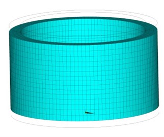
a) Displaced structure with undeformed edge
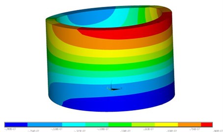
b) Harmonic analysis results, component of displacement
Fig. 2Electrodes scheme and contacts points of cylindrical piezorobot
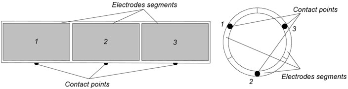
When voltage is applied, the cylinder deforms in a suitable form and contact points create the required motion for piezorobot (Fig. 2).
3. Mathematical model for contact excitation duration for non-rotational robot
A piezorobot consisting of three segments () is analyzed. Movement is created by exciting one of the segments therefore the robot moves from one trajectory point to another without any rotation (Fig. 3).
Fig. 3Structure of piezorobot’s control and path verification system
Movement trajectory is calculated using contact switching algorithm which is explained in detail in source [12]. This algorithm gives information about movement points () of a robot, distance between the coordinates and the number of segment which should be excited using a force . Direction of coincides with the displacement direction and value is constant throughout the movement. Excitation force should affect the segment for duration of until the required destination is reached or required distance is travelled.
It is known that:
where – acceleration of piezorobot, – velocity at the beginning, – velocity after time, – movement time, 1, 2,….
Time can be derived from Eq. (1) as follows:
When active segment number and coordinates are known, it is possible to calculate displacement between coordinates as shown in Fig. 3 [12]:
Displacement can expressed using piezorobot‘s velocity and acceleration :
Acceleration can be expressed as follows:
where – mass of piezorobot, – excitation force of a segment,
Time which takes the piezorobot to move from coordinates to can be expressed through velocity :
When the segment is active, time can be expressed as:
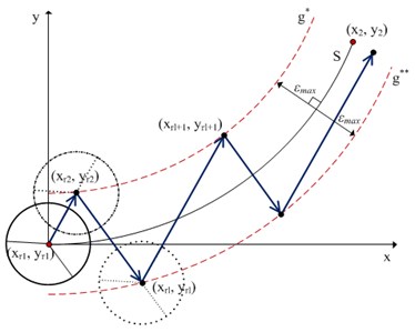
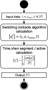
Excitation time algorithm is shown in Fig. 4. – orientation angle of robot in respect of axis (the first symmetry axis of segment angle in respect of axis). – maximum possible movement trajectory error from planned trajectory, – planned movement trajectory [12].
Algorithm calculates duration of excitation for specific segment .
Fig. 4General active segment time calculating algorithm
4. Experimental investigation of contact excitation duration for non-rotational robot
An experimental system for control of piezorobot and trajectory movement tracking was created. It consists of cylindrical piezorobot, control signal formation and image processing system for trajectory tracking of piezorobot. Control system is presented in Fig. 8.
Fig. 8The structure of the piezorobot control and path verification system
Piezorobot is moving on a glass plate. The control signal of piezorobot was amplified using high voltage amplifier and interface to hardware output was set according to the technical requirements of National Instruments NI-DAQmx hardware [14, 15]. Signals are monitored using a system with oscilloscope and object tracking is implemented using video camera with LabVIEW based image processing software. The experimental system is shown in Fig. 9.
Fig. 9Computer based experimental system
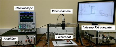
The control software of piezorobot is based on LabVIEW and designed to operate on industry PXI (PCI eXtensions for Instrumentation-NI PXIe-1062Q) computer system. Image tracking subsystem is based on LabVIEW as well and works with high resolution industry camera (Basler Scout SCA 1600-14 gm).
Piezoelectric cylinder type piezorobot used in practical experiments is presented in Fig. 10 and function diagram of expriment system is shown in Fig. 11.
Fig. 10Electrode segments of piezorobot and topology of contact points
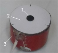
a) Top view of piezorobot. Where 1, 2, 3, segments of electrode, 4 – orientation arrow)
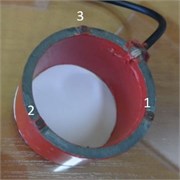
b) Bottom view of piezorobot. Where 1, 2, 3 – contact points
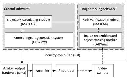
Fig. 11Control of piezorobot and trajectory tracking system block diagram
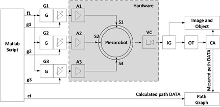
The trajectories planning module software is based on MATLAB and is used to calculate the trajectories of piezorobot [12]. Analog signal control sequence for control of piezorobot was formed using signals formation and distribution system. Analog output hardware DAQ (Data Acquisition NI PXIe-1062) is a physical equipment that distributes the analog signals to the physical outputs. Piezorobot moves on glass surface using high voltage (up to 160 Vp-p) sinusoidal signal therefore analog amplifier is needed.
Trajectory planning software was integrated into the LabVIEW software with MATLAB module (M) forms a sinusoidal frequency control signal (f) for three sinusoidal signal generators G1, G2 and G3. They create sinusoidal 52.5 kHz signal for the control of piezorobot. Amplitude control signals (g1, g2, g3) change the amplitude of each signal at the right time and manage the amplifiers A1, A2 and A3. Each segment of piezorobot (1, 2 and 3) receive an enhanced signal and individually manages the amplitudes according to algorithm given by mathematical module M. The mathematical module calculates variables’ values according to given piezorobot’s algorithm.
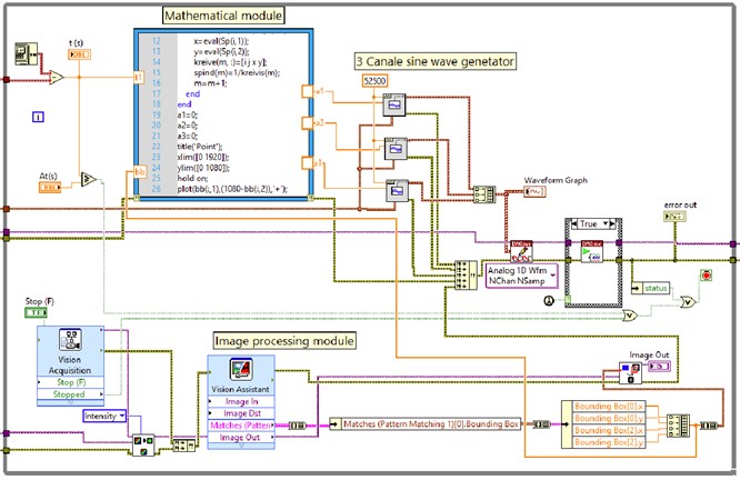
Hardware control software is based on LabVIEW and uses MATLAB script as a mathematical module (Fig. 12). The trajectory speed was set manually using real time clock that was set in milliseconds with external multiplication. Three channel sine wave generator was created with LabVIEW and controlled using MATLAB script. The same script generates path data for trajectory monitoring.
Trajectory monitoring part consists of industrial video camera VC and image processing software. The software is designed for visual tracking with image grabber IG. Object tracker (OT) is designed to track piezorobot and create an array of path coordinates (CA). Movement of piezorobot is observed in real time through Image and Object module and trajectory path graph is generated. Path trajectory monitoring module simultaneously receives theoretical coordinates from MATLAB script module.
Fig. 12Piezorobot’s control and path monitoring software LabVIEW block diagram
5. Experimental results
According to Eq. (4) MATLAB module generates control signal sequence in real time. Control signal of each segment in both experiments (when – ±1 mm and – ±3 mm) lasts for a specific time interval as shown in Table 1.
Control signal generation for each segment of piezorobot is done using the algorithm presented in Fig. 13. The generated control signal is distributed to three segments with contact points. Physical control signal is received with DAQmx analog output and is monitored with oscilloscope. Diagrams of signal distribution to segments are shown in oscillogram (Fig. 14) and the path of the piezorobot is presented in Fig. 15.
In order to validate theoretical algorithms video camera was tracking movement trajectory of piezorobot. Image processing algorithms and coordinate tracking methods are not discussed in detail because they are standard for NI Vision package. Coordinate tracking methods are similar to those presented in [20], however overall algorithm build in NI Vision software is less complex and more universal.
Coordinates were obtained with LabVIEW and presented using MATLAB (Fig. 16).
Table 1Specific time interval of control signal
The experiment with – ±1 mm | The experiment with – ±3 mm | ||||||||||
, mm | , , | , , | , , | , mm | , , | , , | , , | ||||
3 | 1 | 14,688 | 1,851 | 9 | 1 | 4,545 | 3,597 | ||||
4 | 3 | 8,348 | 4,438 | 10 | 3 | 1,604 | 1,935 | ||||
5 | 1 | 20 | 6,831 | 11 | 1 | 6,417 | 3,869 | ||||
6 | 2 | 13,75 | 5,664 | 13 | 2 | 4,011 | 3,059 | ||||
7 | 1 | 7,188 | 4,095 | 13 | 1 | 4,813 | 3,351 | ||||
8 | 2 | 6,875 | 4,005 | 14 | 2 | 3,743 | 2,955 | ||||
9 | 1 | 9,063 | 4,598 | 15 | 1 | 1,604 | 1,935 | ||||
Where – step number, – segment number, – distance in mm that piezorobot travels in one step, – time elapsed from the beginning of experiment, , , , , – time when segments c1, and are active | |||||||||||
Fig. 13Segments’ control algorithm
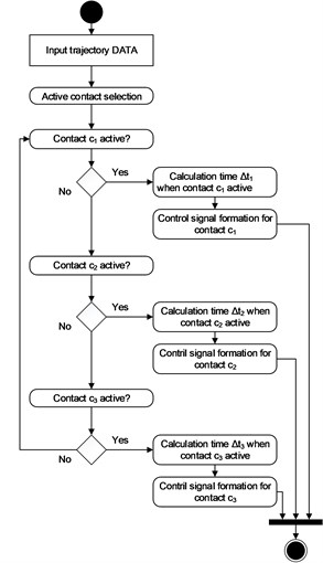
Fig. 14Electrical signals on segments of piezorobot. T0 – start time, T1,…, T6 time from start to control signal end of each segment
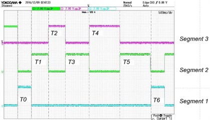
Fig. 15Object tracking and path plotting window. 1 – Tracking point on piezorobot, 2 – path of piezorobot, 3 – path plotting window
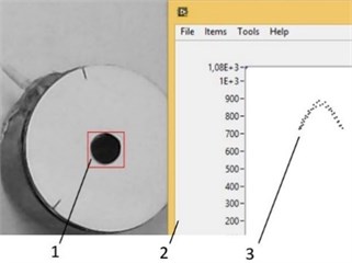
Fig. 16Trajectories of piezorobot obtained during the experiment. Here εmax – calculated error, εmax' – measured error
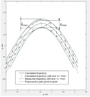
a) Calculated error – ±1 mm
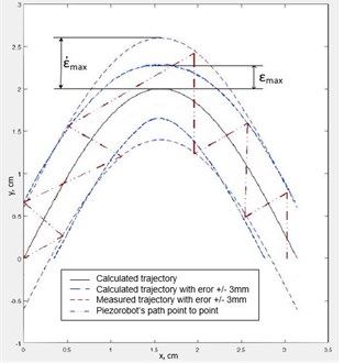
b) Calculated error – ±3 mm
The results showed that when calculated error is estimated to be ±1 mm, measured error aquires values ±1.36 mm and when is ±3 mm, measured error is ±4.6 mm.
Percentage error:
where – calculated coordinate error, – mesured coordinate error. Percentage errors calculated by the Eq. (5): when ±1 mm: –26 %, and when ±3 mm –53.33 %.
When ±1 mm (Fig. 16(a)) the error is smaller due to smaller formation step. In case when ±3 mm (Fig. 16(a)) the step is rougher which leads to bigger error. If errors are predicted using probabilities and the step is chosen then both methods give similar errors.
6. Conclusions
A new trajectory planning method was proposed and evaluated. Motion of the piezorobot is formed using new segments excitation scheme when two or more segments are excited to obtain linear motion without rotation. Trajectory planning method was validated using special experimental system.
1) Piezorobot moves in required trajectory with acceptable accuracy;
2) Experimental trajectory is similar to theoretical therefore this method can be applied for control of piezorobot.
3) The accuracy of trajectory depends on chosen error therefore it is important to optimize the algoritm by chosing optimal number of steps;
4) Calculated error reaches maximum value only where trajectory bends. This happens because generated force vector is not aligned with movement direction. It is necessary to rotate piezorobot at a different angle at bending points. If such adjustments are made then the discussed method is suitable when piezorobot rotates [12].
References
-
Xiang X., Yulie W., Xiaomei W., Yi T., Xuezhong W. Investigation on standing wave vibration of the imperfect resonant shell for cylindrical gyro. Sensors and Actuators A: Physical, Vol. 179, 2012, p. 70-77.
-
Shaobo N., Cui Zhang Attitude determination of nano satellite based on gyroscope, sun sensor and magnetometer. Procedia Engineering, Vol. 15, 2011, p. 959-963.
-
Ahmad K., Christof H., Hubert R. Data fusion of stereo vision and gyroscope for estimation of indoor mobile robot orientation. IFAC Proceedings Volumes, Vol. 45, Issue 4, 2012, p. 163-168.
-
Votrubec R. Stabilization of platform using gyroscope. Procedia Engineering Vol. 69, 2014, p. 410-414.
-
Minase J., Lu T., Cazzolato B., Grainger S. A review, supported by experimental results, of voltage, charge and capacitor insertion method for driving piezoelectric actuators. Precision Engineering, Vol. 34, Issue 4, 2010, p. 692-700.
-
Gozen Arda B., Ozdoganlar Burak O. Characterization of three-dimensional dynamics of piezo-stack actuators. Mechanical Systems and Signal Processing, Vol. 31, 2012, p. 268-283.
-
Kima J. J., Choib J. M., Ahna D., Beomseok B., Gweona D. G., Jeongf J. A millimeter-range flexure-based nano-positioning stage using a self-guided displacement amplification mechanism. Mechanism and Machine Theory, Vol. 50, 2012, p. 109-120.
-
Grybas I., Bansevičius R., Bubulis A., Jūrėnas V., Janutėnaitė J., Kulvietis G. R&D of high resolution rotary table based on the ultrasonic standing waves. Vibroengineering Procedia, Vol. 3, 2014, p. 55-58.
-
Zheng J., Salton A., Fu M. Design and control of a rotary dual-stage actuator positioning system. Mechatronics, Vol. 21, Issue 6, 2011, p. 1003-1012.
-
Bansevičius R., Kulvietis G., Janutėnaitė J., Rybokas M. Analysis of cylindrical piezoelectric actuator used in 3-DOF deflectors. Proceedings of the 7th International Conference on Engineering Mechanics, Structures, Engineering Geology, 2014, p. 86-91.
-
Alijani F., Amabili M. Non-linear vibrations of shells: a literature review from 2003 to 2013. International Journal of Non-Linear Mechanics. Vol. 58, 2014, p. 233-257.
-
Drukteiniene A. Trajectories’ Formation for Mobile Multidimensional Piezorobots with Nanometer Resolution. Doctoral Dissertation, Technika, 2011.
-
Bansevicius R., Drukteiniene A., Kulvietis G., Mazeika D. Switching leg method for trajectory planning of mobile piezorobot. Journal of Vibroengineering, Vol. 12, Issue 1, 2010, p. 26-33.
-
Shujiao J., Yanmin L., Wanli Z. The design of data acquisition system based on virtual instrument. ICCSNT, 2nd International Conference, 2012.
-
Sumathi S., Surekha P. LabVIEW Based Advanced Instrumentation Systems. Springer, Berlin Heidelberg, New York, 2007.
-
Aboshosha A. Adaptive Navigation and Motion Planning for Autonomous Mobile Robots. Doctoral Dissertation, der Fakultät für Informations und Kognitionswissenschaften der Eberhard-Karls-Universität, Tübingen, 2004, p. 66-84.
-
Xuezhi W., Ling, Yu X., Wei F. A rapid learning algorithm for vehicle classification. Information Sciences, Vol. 295, Issue 1, 2015, p. 395-406.
-
Gu B., Sheng V., Tay K., Romano W., Li S. Incremental support vector learning for ordinal regression. IEEE Transactions on Neural Networks and Learning Systems, Vol. 26, Issue 7, 2015, p. 1403-1416.
-
Xia Z., Wang X., Sun X., Liu Q., Xiong N. Steganalysis of LSB matching using differences between nonadjacent pixels. Multimedia Tools and Applications, Vol. 75, Issue 4, 2016, p. 1947-1962.
-
NI Vision Concepts Manual North Mopac Expressway Austin. Texas 78759-3504, National Instruments Inc., USA 2004.
About this article

This research is funded by Research Council of Lithuania, Project No. MIP-084/2015.
Eugenijus Macerauskas created an experiment control system of piezorobot, designed LabVIEW based piezorobot control software and performed an experiment of the piezorobot control and movement by the calculated trajectory. Jurate Janutenaite-Bogdaniene was responsible for modelling and finite element analysis prior to experiments. Analysis allowed to determine suitable geometrical parameters, oscillations and contact points' trajectories. She is the corresponding author of the presented paper. Ramutis Bansevicius conceived the concept of mobile robots and multi-degree-of-freedom trunk robots. He also developed design of the investigated piezoelectric robot. Genadijus Kulvietis analysed and summarized trajectory planning algorithms of piezorobots. Asta Drukteiniene developed trajectory planning method for piezorobot and conducted numerical experiments for verification of created algorithm.
