Abstract
Only when the natural frequency of the TMD is consistence with the main structure’s natural frequency, can tuned mass damper (TMD) achieve a good damping effect. With engineering structure being used for a long time, the natural frequency of the main structure would change. It greatly reduces the traditional TMD’s damping effect. In order to overcome this drawback of TMD, this paper proposes a frequency adjustable TMD device based on magnetorheological elastomers (MREs), in combination with MRE’s adjustable stiffness features. Using the HHT transform and natural excitation method to identify the natural frequency of the main structure, the shear modulus of MRE is adjusted to trace the natural frequency of the main structure. Finally this paper simulates the vertical vibration response of an annular footpath. The results show that the adjustable TMD device can overcome the deficiency of the traditional TMD and achieving a good damping effect within a wide frequency range.
1. Introduction
The tuned mass damper (TMD) is a passive control device of structural vibration. It can offset a part of external force exerted on the main structure, thus achieving the purpose of reducing vibration. Because of its simpleness and economy, TMD is widely applied in structural vibration control. The most typical example is the installed TMD in Taipei 101 building. After TMD was installed of the top floor of this building, the horizontal acceleration of the building has been decreased from 8 mg to 5 mg [1].
Only when its vibration frequency is consistent with some certain natural frequency of the main structure can TMD achieve a good damping effect. The structural stiffness degradation caused by fatigue damage, corrosion and rapid change of live loads all lead to changes in its natural frequency. In this case, the control effect of TMD decreased quickly. In order to overcome this deficiency, Isua and Xu have proposed MTMD system [2], while Chang has proposed active TMD (ATMD) system [3]. Although these devices can make up the deficiency of TMD, they are difficult to install and ATMD requires a great amount of extra input energy.
Magnetorheological elastomers (MREs), as a new branch of magnetorheological material is a kind of highly-elastic composite material [4]. With great continuous controllability, reversibility, and fast response, the shear modulus of MR elastomers can be controlled by applied magnetic field. With reference to the traditional TMD design method, using the field-dependant mechanical properties of the MREs, this paper proposed the new frequency-adjustable TMD device. The MREs serve as the elastic and damping element. We change the frequency-adjustable TMD’s natural frequency by adjusting the applied magnetic. Firstly we identify the natural frequency of the main structure. Then change the stiffness of frequency-adjustable TMD and let its natural frequency keep consistent with the natural frequency of the main structure. As a result the frequency-adjustable TMD can still attenuate the main structure’s vibration regardless of the change in main structure’s natural frequency.
2. Identification of natural frequency of the main structure
In order to keep the frequency-adjustable TMD’s frequency consistent with the natural frequency of main structure all the time, we firstly analyzed the structural response signals under environmental excitation to identify the structure’s natural frequencies. Because these signals are non-linear and non-stationary signals, we analyze them through the method of the combination of the Hilbert Huang Transform (HHT) and the natural excitation (NExT) [5].
The structural vibration response signals measured by the sensor set as , and through the Fourier spectrum we can determine the approximate frequency for th natural frequency. To lessen the mode mixing problem in HHT, we process the signal through band-pass filters with a frequency band , the new signal obtained from the band-pass filters is . Then through empirical model decomposition is resolved into intrinsic modes which meet HHT condition, obtaining the th modal response of the main structure which is also a stationary random signal [6].
To eliminate the end-effects of and increase the identification accuracy, is processed with natural excitation technique to obtain the th natural frequency‘s free attenuation signal [7].
Finally, is processed with Hilbert transform to obtain the instantaneous frequency value of th modal.
3. Working principle and controlling strategy of frequency adjustable TMD
3.1. Working principle of frequency adjustable TMD based on MR elastomers
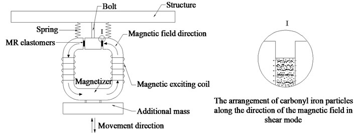
As is shown in Fig. 1, the frequency-adjustable TMD is composed of springs, additional mass, MRE, and magnetic circuits which are used to change the external magnetic field. The magnetic exciting coil on the circuit is connected with the controller, producing controllable external magnetic field. MRE works in shear mode. The direction of the external magnetic field is in parallel with the chaining direction of carbonyl iron particles in MRE, while the shearing deformation direction is perpendicular to that of carbonyl iron particles. When main structure’s frequency remains constant, the frequency-adjustable TMD, similar to traditional ones, provides added inertia force through springs and additional mass; when main structure’s natural frequency changes, the frequency-adjustable TMD alters its stiffness through adjusting the applied current, thus changing its natural frequency and tracing the main structure frequency to achieve a better control effect.
Fig. 1The working principle of the frequency-adjustable TMD
3.2. Controlling strategy and realization procedure of the frequency-adjustable TMD
Compared with traditional TMD the frequency-adjustable TMD has the ability to adjust its stiffness. Its spring element and mass element are designed according to the parameters of traditional TMD.
TMD mass, optimal damping ratio and stiffness are obtained from [8], in order to control the acceleration response of main structure:
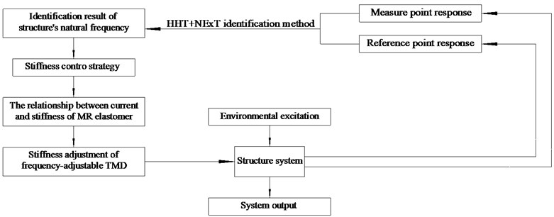
here is the ratio of TMD’s mass to the mass of the main structure; is the natural frequency of the main structure; is main structure’s mass. This formula determines the initial parameters of the frequency-adjustable TMD. When main structure’s natural frequency remains constant, the frequency-adjustable TMD can achieve the same damping effect with the traditional ones. When structure’s natural frequency changes, the frequency-adjustable TMD traces the natural frequency of the main structure and achieve a better damping effect compared with the traditional ones. The whole process shows in Fig. 2
Fig. 2The working process of the frequency adjustable TMD
Since the change of main structure’s frequency has almost no effect on , this parameter can be viewed as constant values. When choosing MRE, the damping ratio of MRE should be as close to the optimal damping ratio as possible.
The stiffness of frequency-adjustable TMD is composed of spring stiffness and MRE’s stiffness. The spring stiffness is only used to bear the weight of mass, whose value is about 5 %-10 % of the MRE’s minimum stiffness value. According to the chain-like model of MRE [9], its stiffness is expressed as:
where and are the area and thickness of MRE respectively; is the zero-field shear modulus; is the correction factor, which is related to external magnetic field intensity; is the particle radius; is the distance between two particles; and are vacuum magnetic conductivity and particle magnetic conductivity; is the particle volume percentage; is the particle magnetization coefficient; is the turns of coil; is the input current; is the length of magnetic circuit; is the angle of the chains; is the position of particle chain’s distribution center; is the rate of divergence of the distance between the particle chain and the center.
According to Eq. (3) and (4), when main structure’s frequency changes, the frequency of frequency-adjustable TMD can be altered by adjusting the input current to keep its natural frequency consistent with the natural frequency of the main structure.
4. Vertical vibration control of annular footpath
4.1. Vertical vibration control of the traditional TMD
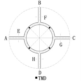
A pedestrian annular footpath was constructed in a building as is shown in Fig. 3. It is 30 meters in diameter, 2.4 meters in width and the arc of each span is 23.5 meters long. At four entrances A, B, C, D, it is rigidly connected, while at E, F, G, H, it is jointed with hinges. Its first three order frequencies are 1.7817 Hz, 2.5995 Hz, 3.0327 Hz; people walking frequency is between 1.5 Hz-3.0 Hz, which results in substantial vertical vibration of the main structure. If the pedestrian load is uniformly distributed on the whole footpath when the density is 0.5 people/m2 the frequency is set to be 3.0 Hz and time duration is 30 s, the peak acceleration value of the annular footpath reaches 0.441 m/s2, greatly exceeding the limiting value of vertical vibration acceleration 0.15 m/s2 [10]. Hence it is necessary to implement the vertical vibration control on the annular footpath.
Considering that its maximum vertical vibration response is at the middle of each span, 4 TMDs are arranged at these places, as is shown in Fig. 3. Take the third-order vibration as an example we illustrate the process of the vibration control. The third-order modal mass of the main structure is 338472 kg. The mass ratio of TMD is set to be 0.01 ( 0.01). Because the circular path is composed of steel and concrete according to engineering experience and seismic code requirements the structural damping ratio is set to be 5 % (5 %). According to Eqs. (1)-(3), the mass of each TMD is 846 kg, the stiffness is 304136 N/m, and the damping ratio is 0.0608. After installing TMDs, the same pedestrian load is exerted on the annular footpath. The structure’s peak acceleration is 0.0969 m/s2, which proves that the traditional TMDs can achieve a good damping effect if the natural frequency of the footpath remains constant.
Fig. 3The profile map of the circular path
4.2. Vertical vibration control of the frequency-adjustable TMD
Decrease the natural vibration frequency of the annular footpath deliberately by 30 %, and use finite element software to calculate its vertical acceleration response under environmental excitation. Identify the footpath inherent frequency by the method mentioned in Section 2. As is shown in Table 1, the results are quite accurate.
After the main structure’s frequency is decreased by 30 %, stiffness of the frequency-adjustable TMD should be changed from 300389 N/m to 178196 N/m according to Eq. (4). Select natural rubber-based MRE whose zero-field shear modulus is 0.8 MPa, the relative MR effect is 233 %, damping ratio is 0.055, and thickness is 3 mm [11]. According to the requirements of stiffness adjustment the diameter of MRE should be 18 mm the finite element analysis shows that when input current is 3 A and the coil number is 400 turns the magnetic induction intensity in MRE area can reach 0.89 T, which meets the stiffness adjustment requirements. According to the chain-like model of MRE, the relationship between TMD stiffness and input current is:
When the main structure frequency does not change, the imputing current is 2.37 A; when it changes, the imputing current is decreased to 1.2 A.
Table 1The comparison between circular path frequency identification results and the FEM simulation results
No. | ANSYS (Hz) | HHT+NExT (Hz) |
1 | 1.3705 | 1.3556 |
2 | 1.9995 | 2.0365 |
3 | 2.3329 | 2.3309 |
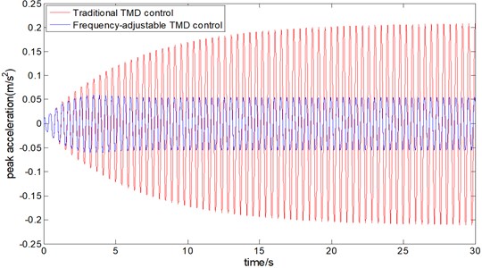
If pedestrian load is 0.5 people/m2 in density and 3.0 Hz in frequency which lasts 30 s is exerted on the annular footpath, the damping effect is shown in Fig. 4. Apparently, the peak acceleration of the footpath with traditional TMDs is increased to 0.2015 m/s2, which cannot meet the comfort level with peak acceleration of 0.15 m/s2. This is caused by the inconsistency between the traditional TMD frequency and the changed structural frequency. But the peak acceleration of the footpath with frequency-adjustable TMD is only 0.061 m/s2, producing marvelous damping effect. This means that the frequency-adjustable TMD can achieve a good damping effect in a wider frequency range by changing the input current.
Fig. 4The vertical vibration acceleration peak value of the circular path
5. Conclusions
This paper proposed the frequency-adjustable TMD device based on MRE which is characterized by simple configuration, low energy consumption, and easy application. The natural frequency of the main structure can be accurately identified by combination of the HHT and the NExT; MRE can adjust TMD’s frequency in a wider frequency band, keeping the natural frequency of the frequency-adjustable TMD consistent with the natural frequency of the main structure, thus achieving good damping effect when main structure’s frequency changes. This paper only proposed the idea and theoretical analysis method of frequency-adjustable TMD, further trials are in progress.
References
-
Teng Jun The Theory, Technology and Method of Structural Vibration Control. Science Press, Beijing, 2009, p. 163-164.
-
Igusa T., Xu K. Vibration control using multiple tuned mass dampers. Journal of Sound and Vibration, Vol. 175, Issue 4, 1994, p. 491-503.
-
Chang J. C. H., Soong T. T. Structural control using active tuned mass damper. ASCE Journal of Engineering Mechanics, Vol. 106, Issue 6, 1980, p. 1091-1098.
-
Gong Xinglong, Deng Huaxia,Li Jianfeng,Chen Lin, Zhang Peiqiang Magnetorheological elastomers and corresponding semi-active vibration absorption technology. Journal of University of Science and Technology of China, Vol. 5, Issue 10, 2007, p. 1192-1203.
-
Han Jianping, Li Dawen Modal parameter identification based on Hilbert-Huang transform and natural excitation technique. Engineering Mechanics, Vol. 27, Issue 8, 2010, p. 54-59.
-
Huang N. E., Shen Z., Long S. R. The empirical mode decomposition and the Hilbert spectrum for nonlinear and non-stationary time series analysis. Proceeding of the Royal Society of London Series A, Vol. 454, 1998, p. 903-995.
-
James G. H., Carrie T. G., Lauffer J. P. The Aatural Excitation Technique (NExT) for Modal Parameter Extraction from Operating Wind Turbines. Sandia National Laboratories, Albuquerque, New Mexico, 1995.
-
Kazuto Seto Dynamic Vibration Absorber and Its Applications. Mechanical Industry Press, Beijing, 2013, p. 38-39.
-
Yu Miao, Xia Yongqiang, Yan Xiaorui Analysis and verification on the chain-like modal with normal distribution of MR elastomer. Chinese Journal of Chemical Physics, Vol. 22, Issue 5, 2009, p. 545-550.
-
JGJ3-2010, Technical Specification for Concrete Structures of Tall Buildings. China Architecture and Building Press, Beijing, 2010.
-
Chen Lin The Development and Mechanical Characterization of Magnetorheological Elastomers. University of Science and Technology of China, 2009, p. 93-95.
About this article

This research was supported by the National Natural Science Foundation of China (Grant Nos. 51178368, 51278393, 51478372). Thanks for the financial support for this study.
