Abstract
This study aims to carry out the frictional analysis of cam-controlled planetary gear trains through an illustrative example. First, the equations for frictional analysis proposed in the previous study are presented. Then, the results of friction force and couples are obtained by numerical analysis. The results indicate that a cam-controlled planetary gear train is of high mechanical efficiency, but will induce significant vibration.
1. Introduction
A cam-controlled planetary gear train (CCPGT) refers to a planetary gear train with cam pairs [1]. Rothbart [2] called CCPGT as epicyclic gears and moving (or fixed) cam, and illustrated three kinds of CCPGTs. Chironis [3] also illustrated a CCPGT in his book. Fig. 1 show, the exploded view and the structural sketch of the train. It consists of a cam groove (the frame, member 1), an arm (member 2, the input), a planetary gear (member 3), and a sun gear (member 4, the output). Generally, the planetary arm rotates at constant speed, and then the planetary gear is driven to rotate around the sun gear and to spin around itself concurrently. Simultaneously, the planetary gear will produce an oscillatory motion generated by the contact of the attached roller and the cam groove. Therefore, the output (sun gear) will produce a non-uniform motion through the engaging with the planetary gear. The key advantage is that it can produce a varied non-uniform output motion. It is now at work in film drives, e.g. the paper feeding of automatic die cutting and creasing machine, etc.
Fig. 1Cam-controlled planetary gear trains
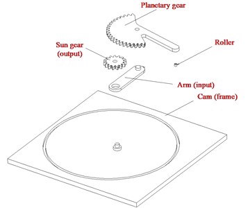
a) Exploded view [1]
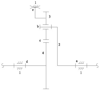
b) Structural sketch [4]
Although CCPGTs are introduced in Rothbart’s and Chironis’ books, but the approaches of analysis and design are not addressed. Hsieh et el. [1, 4-6] coducted a series of systematic investigations on CCPGTs, including kinematic and experimental studies [1], kinematic synthesis [4], structural synthesis [5], modeling and control [6], and kinetostatic and mechanical efficiency analyses [7, 8].
The purpose of this study is to carry out the frictional analysis of cam-controlled planetary gear trains through an illustrative example. In Section 2, the equations of frictional analysis proposed in the previous study will be outlined. Then, Section 3 will be devoted to conduct the numerical analysis for frictional force and couples. Finally, conclusions will be drawn in Section 4.
2. Friction analysis
The approach of frictional analysis of CCPGTs had been developed in Ref. [7]. The equations of frictional forces and couples are summarized here.
The normal force and the friction force acting on each revolute joint can be equivalently expressed as a resultant force passing through the pin center and a couple . The friction couple can be expressed as:
where is the coefficient of kinetic friction between and , is the pin radius of member , is the resultant force passing through the pin center, and is a direction indicator that can be determined by:
Similarly, the forces between a cam joint with a roller follower can be formulated as those of a revolute joint, except is replaced by a coefficient of rolling friction. And in the same way, the friction force, due to relative velocity, between the engaging teeth of two gears can be formulated by:
where is the directional indicators of the relative velocity between the contacting point of the two engaging teeth, and can be determined by:
Based on the equations above and the solving procedure in Ref. [7], each friction forces and couples can then be found by applying an adequate numerical approach.
3. Design example
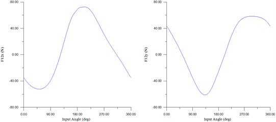
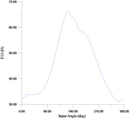
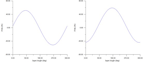
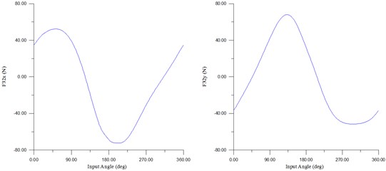
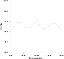
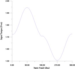
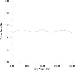
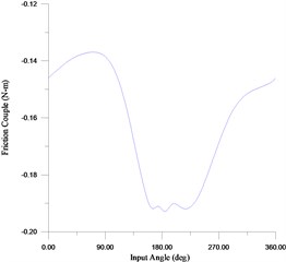
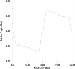
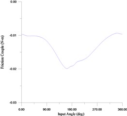
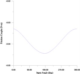
The loading torque and the input speed are set as 1.5 N-m and 120 rpm, respectively. Moreover, the geometric dimensions and inertial parameters employed in this example are the same as listed in Table 1 of Ref. [8]. Fig. 2 shows the numerical results of the reactional forces acting between each part and the required input torque. It is found that the reactional forces change dramatically, therefore vibration will be a major concern for precision applications. Fig. 3 depicts that the magnitudes of the frictional force and couples are small, therefore the mechanical efficiency is high. There is a directional change between the arm (part 2) and the planetary gear (part 3), a special care must be taken during the numerical solving.
Fig. 2Reaction forces and the input torque
a)
b)
c)
d)
e)
f)
4. Conclusions
In this work, the friction analysis, proposed by the previous study, of the CCPGT has been performed. The reaction forces and the required input torque have been solved, and the fiction force and couples have also been obtained. The results have indicated that a cam-controlled planetary gear trains is of high mechanical efficiency. However, significant vibration will be induced, and should be minimized for precision and/or high speed applications.
Fig. 3Friction force and couples
a)
b)
c)
d)
e)
References
-
Hsieh W. H. An experimental study on cam controlled planetary gear trains. Mechanism and Machine Theory, Vol. 42, Issue 5, 2007, p. 513-525.
-
Rothbart H. A. Cams: Design, Dynamics and Accuracy. Wiley, New York, 1956.
-
Chironis N. P. Mechanisms and Mechanical Devices Sourcebook. McGraw-Hill, New York, 1991.
-
Hsieh W. H. Kinematic Synthesis of cam-controlled planetary gear trains. Mechanism and Machine Theory, Vol. 44, Issue 5, 2009, p. 873-895.
-
Hsieh W. H., Chen S. J. Innovative design of cam-controlled planetary gear trains. International Journal of Engineering and Technology Innovation, Vol. 1, Issue 1, 2011, p. 1-11.
-
Hsieh W. H., Lee I. C. Modelling and control of cam-controlled planetary gear trains. International Journal of Modelling, Identification and Control, Vol. 12, Issue 3, 2011, p. 272-279.
-
Hsieh W. H. Kinetostatic and mechanical efficiency studies on cam-controlled planetary gear trains – part 1: theoretical analysis. Indian Journal of Engineering and Materials Sciences, Vol. 20, Issue 3, 2013, p. 191-198.
-
Hsieh W. H. Kinetostatic and mechanical efficiency Studies on cam-controlled planetary gear trains – part 2: design and experiment. Indian Journal of Engineering and Materials Sciences, Vol. 20, Issue 3, 2013, p. 199-204.
About this article

The support of the Minster of Science and Technology, Republic of China (Taiwan), under Grants NSC 92-2212-E-150-035 and MOST 104-2221-E-150-054 is gratefully acknowledged.
