Abstract
This paper deals with the problem of getting dynamic characteristics in complex mechanical multi-body system. Based on the MFBD (Multi-Flexible-Body Dynamics) technology, the rigid-flexible coupling dynamic simulation method is proposed, and then the method is applied to the planetary gear transmission. The results show that the dynamic stress distribution of planetary gear can be obtained to determine the dangerous location, and the dynamic response characteristics are more obvious. Then the simulation model of planetary gear transmission with broken tooth is established, the fault feature extraction in time-frequency domain is carried out using the acceleration signal. In addition, industrial data is also used to validate the effectiveness of the proposed method.
1. Introduction
Acquisition of state information is a key aspect in PHM (Prognostics and Health Management), but it is difficult to acquire the dynamical characteristics of key components in the large-scale, complex equipment [1, 2]. Development of virtual prototype technology has greatly improved the status. Compared with the traditional multi-rigid body model, the description of component status in multi-flexible body system can be more accurate, but the high nonlinear and complex coupling characteristics also lead to difficulties of the dynamic modeling and solving, therefore it remains need to be further studied on the theory and application [3-5].
The traditional research of rigid-flexible coupling modeling is mainly on the modal reduction method which the stiffness of flexible structure is expressed by the modal by finite element calculation in advance, but the method is limited because it can’t solve the large deformation and the nonlinear problems [6-8]. Based on the MFBD technology, the modal reduction method is extended by using the node method which put the finite element analysis and multi-body dynamics analysis in the same solver, therefore it can directly obtain structure characteristics and effectively solve large deformation and nonlinear problems [9-11].
The remaining sections of this paper are organized as follow. In Section 2, the theory of rigid-flexible coupling dynamics was illustrated. In Section 3, the framework of simulation method was proposed and the rigid-flexible coupling model of the planetary gear transmission is established. In Section 4, the simulation results were analyzed. Section 5 validated the proposed method using industrial data. Finally, the conclusions were drawn in Section 6.
2. Rigid-flexible coupling dynamics theory [12, 13]
2.1. Multi-body dynamics theory overview
The object speed in absolute coordinate system can be defined as Eq. (1):
wherein, is the number of coordinates in the absolute coordinate system.
The object speed in relative coordinate system can be defined as Eq. (2):
wherein, is the number of coordinates in the relative coordinate system.
Thus, the Cartesian speed of all objects can be denoted as Eq. (3):
The coefficient matrix can be denoted by relative coordinates.
The system motion equations can be derived by the first kind Lagrange equation as Eq. (4):
wherein, is mass matrix, is acceleration vector, is derivative of coefficient matrix , is cutting joints constraint, is Lagrange multipliers, is force vector.
2.2. Motion equations of flexible bodies
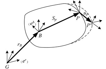
As shown in Fig. 1, position vector of any point P can be defined as Eq. 5:
wherein, is point vector in inertial coordinate system; is the origin vector of the relative coordinate in the inertial coordinate system; is direction cosine matrix; is point vector in relative coordinate system while flexible body is undeformed; is relative deformation vector, the following equation shows that can be denoted by the modal coordinates as Eq. (6):
wherein, is deformation modal matrix, is generalized coordinates of deformation. Therefore, the velocity vector and acceleration vector of any point at Flexible body can be denoted as Eq. (7-8):
Fig. 1Deformation model of flexible body
2.3. Dynamics equations of flexible body
Considering position, direction and modal of the node with the deformation, generalized coordinates of flexible body can be defined as Eq. (9):
Dynamics equation of flexible body is derived by the Lagrange equation as Eq. 10:
wherein, is constraint equation, is Lagrange multiplier corresponding to the constraint equation, is generalized coordinates as Eq. (9) defined, is generalized force projected to , is defined as , is kinetic energy and is potential energy, is energy loss function, the differential equations of motion can be denoted as Eq. (11):
wherein, , , is generalized coordinates time derivatives of flexible body, , is the mass matrix of the flexible body and its time derivative. is stiffness Matrix, is damping matrix. The differential Eq. (11) is solved and imported into the Eq. (7-8), all generalized velocity and acceleration can be obtained.
3. Method and case simulation
3.1. Method and application object
In this paper, based on 3-D modeling software SolidWorks, finite element analysis software ANSYS and multi-body dynamics software RecurDyn, a method to build rigid-flexible coupling simulation model is proposed, the framework is constructed as shown in Fig. 2, the model could be effectively built with interface between these software programs.
Fig. 2Framework of rigid-flexible coupling simulation

Fig. 3Working principle of integrated transmission device
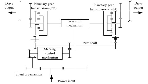
As shown in Fig. 3, the integrated transmission device is dual-power flow form, the power is input from the engine, the direct-flow power flow is transmitted to the ring gear of planetary gear transmission through the gear shift mechanism; while the steering power flow is transmitted to the sun wheel of planetary gear transmission through the steering control mechanism, and the two power streams converge and output at the planetary gear transmission to drive the vehicle to realize direct-driving and steering working condition.
Planetary gear transmission is a key subsystem in the integrated transmission device and its operation reliability directly affect the whole system performance. But in actual using process, due to its complex structure, heavy workload, closed and bad operating environment, it is found of highly failure such as wear, ablation and other faults. Therefore, the dynamic characteristics, fault mechanism, fault diagnosis and feature extraction of the planetary gear transmission should be paid more attention [14-16].
In order to get the dynamic response characteristics considering the effect of elastic deformation. In the case, based on the MFBD technology, the rigid-flexible coupling dynamic model of the planetary gear transmission is studied by using the method proposed.
3.2. Calculation of planetary gear transmission
In the direct-driving conditions, the DOF of planetary gear transmission system is 1, and in the steering conditions, the DOF of planetary gear transmission system is 2. In this paper, the dynamic characteristics of the steering status are simulated. The ring gear and sun gear are used as input and the planet carrier is output.
Fig. 4Epicyclic gear structure
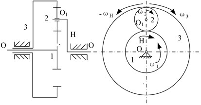
In essence, the planetary gear transmission studied is an epicyclic gear structure as shown in Fig. 4, while the 1th component is the sun gear, the 2th component is the planetary gear, the 3th component is the ring gear, the component is the planet carrier.
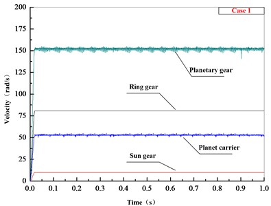
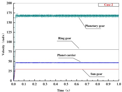
According to actual working conditions, while the engine input speed is 162.2 rad/s, the speed of the direct-driving output (the ring gear rotation speed) is 80.6 rad/s, and in order to make the results more convincing, the input rotation speed (the sun wheel rotation speed) is set in two cases, the first case is 10 rad/s, the second case is 30 rad/s. According to the transmission principle and the gear parameters, the follow results can be calculated as Table 1 shows.
Table 1Calculation values of different case
Case 1 | Case 2 | |
Ring gear | 80.6 rad/s | |
Sun wheel | 10 rad/s | 30 rad/s |
Planet carrier | 52.8 rad/s | 46.8 rad/s |
8.42 Hz | 7.45 Hz | |
Planetary gear | 151.7 rad/s | 167.5 rad/s |
15.74 Hz | 19.22 Hz | |
Planetary system | 220.3 Hz | 269.1 Hz |
3.3. Multi-rigid-body model
After adding constrains and contacts of the components, the driving speed of ring gear and sun gear is set as Table 1 shows, the load torque is set to the output planet carrier as 6000 N·m, the simulation time is set as 1 second, the simulation step is set as 2000.
Fig. 5Multi-rigid-body model
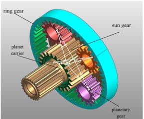
Fig. 6Speed values of planetary gear transmission
a)
b)
The speed values of simulation can be seen in Fig. 6, both in the different case, each component gradually increases to stable condition at about 0.02 s and the rotational speed of the planet carrier and the planetary gear fluctuate in a small range between the calculated value. Compared with the calculation values, the accuracy of the multi-rigid-body model is proved.
3.4. Rigid-flexible coupling model
The finite element model of the planetary gear is built in ANSYS as Fig. 7 shows, then the corresponding model file is generated and exported to RecurDyn.
After importing the finite element model of planetary gear to replace original member, the contact relationship and the original constraints disappear so that the finite element model should be modified [9], as shown in Fig. 8.
(1) A set of nodes and rigid FDR unit is set to replace rotating pair between the planetary gear and planet carrier.
(2) The surface of planetary gear tooth surface is defined as “patch” unit, then the contacts between planetary wheel and contacted parts are built using the finite element flexible body contact module (Surface to Fsurface) in FFLex.
Then contact force parameters are added and then the rigid-flexible coupling model is established as shown in Fig. 9.
Fig. 7planetary gear finite element model
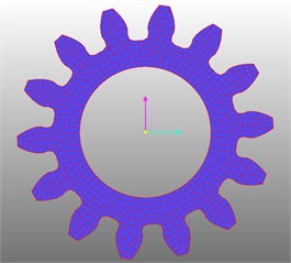
Fig. 8Modification in FFLex
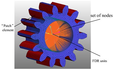
Fig. 9Rigid-flexible coupling model of planetary gear transmission
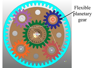
4. Simulation results analysis
4.1. Analysis in normal state
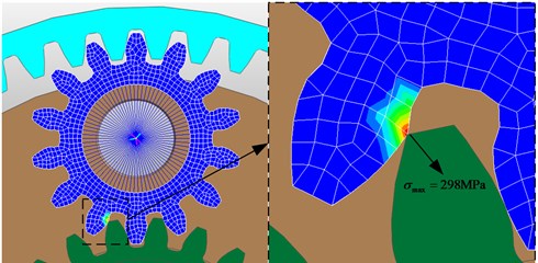
The dynamic stress distribution of planetary gear can be obtained in the post-processing module in RecurDyn. As shown in Fig. 10, the maximum stress of the planetary gear occurs in the red area which is in the end of the planetary gear wheel tooth.
Fig. 10Stress distribution of planetary gear with max stress
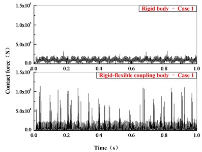
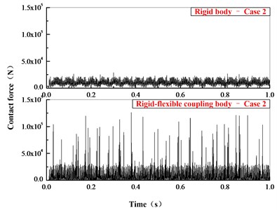
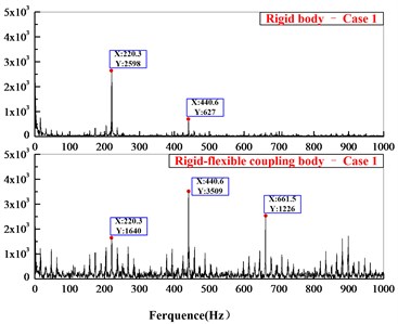
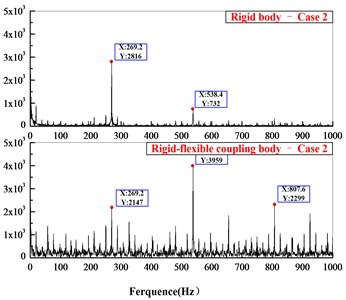
The contact force between planetary gear and sun gear in time domain is shown in Fig. 11. The dynamic contact force in the rigid-flexible coupling model is larger than in the rigid body model, but the calculation values show the average dynamic contact force in the rigid-flexible coupling model is less than in the rigid body model. Fig. 12 is comparison of the contact force in frequency domain, both the meshing frequency of planetary system ( 220.3 Hz, 269.1 Hz) and the frequency multiplier appear in the figure, and compared with the rigid model, the response of the flexible body model in time domain and frequency domain is more obvious.
Compared with the rigid model, the results show that the dynamic stress distribution and dangerous position of the component can be obtained in the rigid-flexible coupling model, and the response characteristics in time domain and frequency domain are more obvious. Therefore, the proposed method can reflect the dynamic response characteristics better.
Fig. 11Comparison of contact force in time domain
a)
b)
Fig. 12Comparison of contact force in frequency domain
a)
b)
4.2. Analysis in fault state
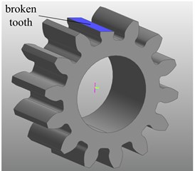
Fig. 13 shows the rigid-flexible coupling model with broken tooth. According to the previous analysis, the maximum stress occurs in the end of the planetary gear wheel tooth. In actual using process, the gear tooth is prone to fracture after repeated fatigue deformation.
Fig. 13Establishment of planetary gear with broken tooth
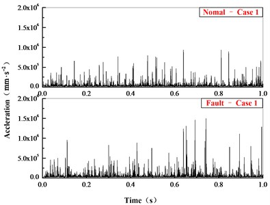
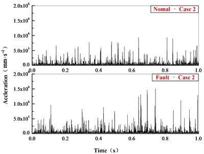
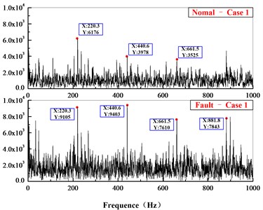
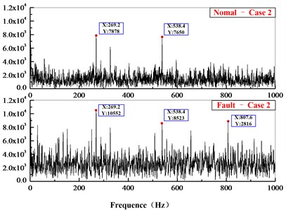
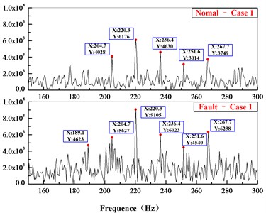
By using the proposed method, the rigid-flexible coupling model with broken fault is analyzed. In engineering practice, it is difficult to test the contact force between the components so that the acceleration signal is used to analysis. As shown in Fig. 14, the acceleration time-domain signal on planetary gear is compared. As Fig. 15-16 show is the frequency-domain signal comparison after FFT transform.
Fig. 14Comparison of acceleration in time domain
a)
b)
Fig. 15Comparison of acceleration in frequency domain
a)
b)
Fig. 16Comparison of acceleration in partly frequency domain
a)
b)
In the time-domain comparison (Fig. 14), there are larger loads after the broken tooth failure compared with the normal state, but its periodicity is not obvious. In the frequency domain comparison (Fig. 16), the meshing frequency of planetary system ( 220.3 Hz, 269.1 Hz) can be seen in normal state, and the sidebands ( 15.74 Hz, 19.22 Hz) are irregularly distributed on the sides. However, due to the aliasing of the frequency, the frequency multiplier and sidebands are not obvious. The amplitude of main frequency and its frequency multiplier increase while the occurrence of broken teeth, and the frequency components and amplitude also increase significantly on both sides of meshing frequency.
5. Experimental validation
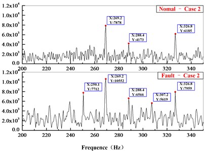
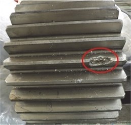
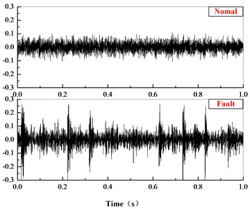
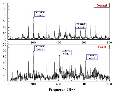
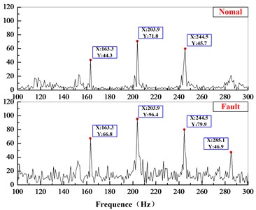
On the viewpoints described above, an industrial data is analyzed to validate the proposed method, and the data is acquired from wind turbines. The type of wind turbine is FL600 and it has been reaching to examine and repair deadline. The detail data of can be seen in document [17]. The wind turbine and its internal structure can be seen in Fig. 17-18. In the unpacking process, the planetary gear is found of damage as the Fig. 19 shows. Then the acceleration signals under fault state are compared with the normal state to validate the effective of the proposed method.
According the parameters and test conditions, the gear-mesh frequency of planetary system is 203.9 Hz, and the gear-mesh frequency of is 40.6 Hz. The data in normal and fault state is analyzed in time and frequency domain, the results are as Fig. 20 show. In time domain, there are larger value of the shock-type vibrations under the fault state; and in the frequency domain, the frequency composition and amplitude increase obviously. The results prove the effectiveness of the method this paper proposed.
Fig. 17FL600 wind turbine gearbox
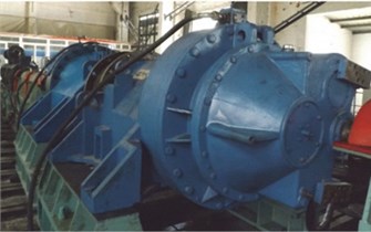
Fig. 18The internal structure
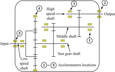
Fig. 19The damaged planetary gear
6. Conclusions
In this paper, the rigid-flexible coupling dynamics simulation method was proposed based on the MFBD technique, and then the planetary gear transmission was analyzed by using the method. The simulation results showed that that the dynamic stress distribution could be obtained to determine the dangerous location and the dynamic response characteristics of rigid-flexible coupling model were more obvious than the rigid model.
Fig. 20Comparison in time and frequency domain
a) Comparison of acceleration in time domain
b) Comparison of acceleration in frequency domain
c) Comparison of acceleration in partly frequency domain
Then a fault model with the broken gear was established, the feature of the broken tooth of the planetary transmission gear system was extracted by using the time-frequency domain analysis of acceleration. In time domain, there were larger value of the shock-type vibrations; in the frequency domain, the amplitude modulation and frequency modulation were generated near the meshing frequency, the frequency components and amplitude increased obviously on both sides. Additionally, industrial data was used to validate the applicability of the proposed method to the practical environment. The results showed that the method this paper proposed still has good performance.
References
-
Chen Z. S., Yang Y. M., Hu Z. A technical framework and roadmap of embedded diagnostics and prognostics for complex mechanical systems in prognostics and health management systems. IEEE Transactions on Reliability, Vol. 61, Issue 2, 2012, p. 314-322.
-
Vogl G. W., Weiss B. A., Helu M. A review of diagnostic and prognostic capabilities and best practices for manufacturing. Journal of Intelligent Manufacturing, 2016, p. 1-17.
-
Zheng E., Zhu R., Zhu S., et al. A study on dynamics of flexible multi-link mechanism including joints with clearance and lubrication for ultra-precision presses. Nonlinear Dynamics, Vol. 83, Issues 1-2, 2016, p. 137-159.
-
Ren Z. S., Yang G., Wang S. S., et al. Analysis of vibration and frequency transmission of high speed EMU with flexible model. Acta Mechanica Sinica, Vol. 30, Issue 6, 2014, p. 876-883.
-
Valembois R. E., Fisette P., Samin J. C. Comparison of various techniques for modelling flexible beams in multibody dynamics. Nonlinear Dynamics, Vol. 12, Issue 4, 1997, p. 367-397.
-
Ki K. O., Kang M. K. Convergence acceleration of iterative modal reduction methods. AIAA Journal, Vol. 39, Issue 1, 2015, p. 134-140.
-
Barbone P. E., Dan G., Patlashenko I. Optimal modal reduction of vibrating substructures. International Journal for Numerical Methods in Engineering, Vol. 57, Issue 3, 2003, p. 341-369.
-
Rumpler R., Legay A., Deü J. F. A substructuring FE model for structural-acoustic problems with modal-based reduction of poroelastic interface. Computers and Structures, Vol. 89, Issues 23-24, 2011, p. 2233-2248.
-
Moon I. D., Yoon H. S., Oh C. Y. A flexible multi-body dynamic model for analyzing the hysteretic characteristics and the dynamic stress of a taper leaf spring. Journal of Mechanical Science and Technology, Vol. 20, Issue 10, 2006, p. 1638-1645.
-
Yang Q. J., Li D. N., Kong L. L., et al. Research on MFBD modeling method for a gantry machining center beam components. International Conference on High Speed Machining, 2011, p. 487-492.
-
Türtscher A., Faßbender F., Kelichhaus D. I. T. Simulation of dynamic stresses including flexible contacts using MFBD technology. SAE Technical Papers, 2006.
-
Deng F., He X., Liang L., et al. Dynamics modeling for a rigid-flexible coupling system with nonlinear deformation field. Multibody System Dynamics, Vol. 18, Issue 4, 2007, p. 559-578.
-
Cardona A., Geradin M. A beam finite element non-linear theory with finite rotations. International Journal for Numerical Methods in Engineering, Vol. 26, Issue 11, 1988, p. 2403-2438.
-
Chen Z., Zhu Z., Shao Y. Fault feature analysis of planetary gear system with tooth root crack and flexible ring gear rim. Engineering Failure Analysis, Vol. 49, 2015, p. 92-103.
-
Wang J., Li R., Peng X. Survey of nonlinear vibration of gear transmission systems. Applied Mechanics Reviews, Vol. 56, Issue 3, 2003, p. 222-227.
-
Chen X. H., Cheng G., Shan X. L., et al. Research of weak fault feature information extraction of planetary gear based on ensemble empirical mode decomposition and adaptive stochastic resonance. Measurement, Vol. 73, 2015, p. 55-67.
-
Li H., Zhao J., Zhang X., et al. Gear fault diagnosis and damage level identification based on Hilbert transform and Euclidean distance technique. Journal of Vibroengineering, Vol. 16, Issue 8, 2014, p. 4137-4151.
