Abstract
According to the movement mechanism of strip and rollers during the continuous rolling process, the main drive system of each stand was simplified to a single degree of freedom discrete model, and the strip was simplified to an axially moving Euler beam. Then, a nonlinear continuous-discrete coupled vibration model between transverse and longitudinal vibrations of strip and torsional vibration of main drive system was established. According to Hamilton’s principle, the nonlinear differential equations were established. Moreover, modified iteration method and Kantorovich averaging method were used to solve the differential equations. Depending on numerical calculation, the amplitude-frequency responses of strip vibration coupled with torsional vibration of main drive system were obtained. Finally, the influences of the axial velocity, the strip tension, the torsional stiffness, and the rotational inertia on the vibration characteristics were discussed. The results would provide a theoretical reference for control and analysis of rolling mill vibration in engineering practice.
1. Introduction
The rolling mill vibration has brought serious troubles to iron and steel industry for many years, which is a significant technical problem. The vibration forms are various, and characteristics and causes are different. At present, the research on the different forms of rolling mill vibration mainly includes vertical vibration and horizontal vibration of rollers, transverse and longitudinal vibration of strip [1, 2], torsional vibration of main drive system [3] and the axial vibration, etc. As early as in 1967, the research of various vibrations of rolling mill was begun. Moller and Hoggart et al. [4] found the existence of torsional vibration of the rolling mill when they were employing the two rolls test machine, and the vibration behavior, which was considered as the self-excited vibration. Lawrence and Thomas [5] analyzed the chatter-mark on the strip surface, which caused torsional vibration by defect of transmission gear. Swiatoniowski and Bar [6] analyzed the chattering phenomenon during the rolling process, and the mathematical model of self-excited vibration was established. Wang et al. [7] analyzed the influence of rolling force on horizontal stiffness of rolling mill, and the functional relationship among the vertical vibration of rolling mill, the horizontal vibration of work roll and the torsional vibration of main drive system was established. Sun et al. [8] investigated the torsional vibration on the dynamic model of six rollers system of 1100 rolling mill, and the influence of torsional vibration on strip shape was acquired. Xu et al. [9, 10] established the hybrid system model of strip coupled with rollers, and the coupled vibration mechanism of roller and strip with tension fluctuation was obtained. Zou et al. [11] analyzed the different influences of cold rolling and hot rolling on axial force, and a mathematical model was established. Du et al. [12] established the nonlinear dynamic model of coupled model between rollers and strip, and the inertial boundary condition was proposed.
However, there are few researches studying on coupled vibration of multiple systems. In the earlier stage, the research of strip vibration coupled with torsional vibration of main drive system has been investigated by our group, such as the vibration analysis of main drive system of each stand by finite element software. Researchers found the energy was transferred from one to another main drive system through the strip when resonance occurred, which resulted to the great fluctuation of rollers, and the vibration amplitude may exceed self-resonance [13]. Therefore, it is significant to analyze the coupled vibration between strip and main drive system of rolling mill furtherly.
In this paper, the main drive system of rolling mill is simplified to a single degree of freedom model of discrete system, and the strip is simplified to an axially moving Euler beam [14, 15]. Then, a continuous-discrete coupled vibration model between transverse and longitudinal vibrations of strip and torsional vibration of rolling mill main drive system is established. The research results can provide important theoretical reference for control and analysis of strip vibration coupled with torsional vibration during the continuous rolling process.
2. Mechanical and mathematical models
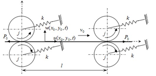
The main drive system of each stand can be regarded as a mass-spring system in the tandem mill, which mainly composed of inertial components of electromotor, reduction gears and rollers etc., and elastic components of connecting shafts, a dimensional geometric model is shown in Fig. 1. Due to the traction behavior of motor drive, the motor of main drive system could be regarded as a fixed end [16]. And the rotational inertia of roller is much bigger than the other parts, so the main drive system can be simplified to a single degree of freedom discrete model of spring-mass system. The rollers can be equivalent to the rigid inertial components, is the rotational inertia and is the rotation angle; the connecting shafts can be equivalent to the elastic element, is the torsional stiffness, as shown in Fig. 2. When transverse and longitudinal vibrations of strip are considered, the mechanical geometry characteristic is similar to an axially moving beam [17, 18]. Also, the strip is an elastic continuum whose thickness is much less than the length, the strip is equivalent to the isotropic Euler beam based on the theory of axially moving beam. The equivalent mechanical model is shown in Fig. 3, and assumes that the strip with uniform motion is running, is the axial velocity. It hypothesizes that there is no relative motion between rollers and strip, and the upper and lower rollers are symmetric discs of fixed axis rotation along the width of beam. The transverse displacement and the longitudinal displacement of Euler beam are and respectively; is the distance of Euler beam between two stands; the left tension and the right tension are and respectively, and .
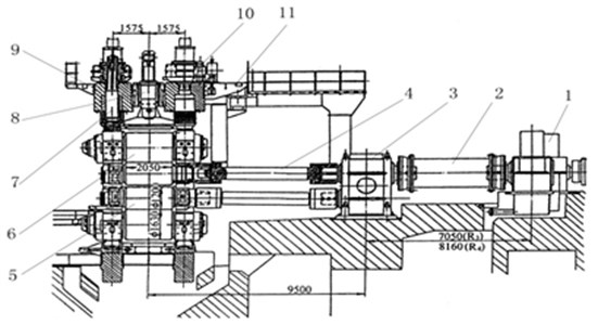
Fig. 1A dimensional geometric model of main drive system of one stand: 1 – electromotor, 2 – intermediate shaft, 3 – reduction gears, 4 – profile spindle, 5 – working roll, 6 – back-up roll, 7 – screwdown device, 8 – balancing device, 9 – unjamming gear, 10 – mill housing, 11 – platform
Based on Hamilton principle, the mathematical model of strip vibration coupled with torsional vibration of main drive system is established.
The kinetic energy of axially moving Euler beam can be written as:
where is the density of strip, is the cross-sectional area of Euler beam, , and , are the and on variables and of the first partial derivatives respectively.
Fig. 2A simplified model of main drive system of rolling mill
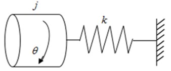
Fig. 3A mechanical model of strip between main drive systems of two stands
The kinetic energy of roller can be written as:
where is the radius of roller.
The potential energy of Euler beam can be written as:
where is the strain of Euler beam, is the Young’s modulus and is the moment of inertia.
The potential energy of tension can be written as:
Then according to Hamilton principle, the following equation can be obtained:
Substitution of Eqs. (1-4) into Eq. (5), the motion equations can be expressed as:
In general, the axial kinetic energy caused by transverse vibration is relatively small. Let , So, Eq. (6) is simplified as:
The relationship between torque and torsional stiffness is expressed as: , where is relative torsional angle between two shaft sections, is the torsional stiffness of shaft segment. Therefore, boundary conditions can be written as:
When :
When :
The time variable of equation is separated from the space variable by substitution of into Eq. (8), the following equation can be obtained as: , where is vibration frequency.
Based on Kantorovich averaging method on the interval , the time variable can be eliminated. The motion equations can be simplified as:
Boundary conditions can be written as, when :
When :
The dimensionless quantities are given by:
Then, the dimensionless form of Eqs. (13-18) can be obtained respectively:
When :
When :
3. Analytical solution of vibration equations
Due to more complicated solving process of the Eqs. (19-24), the modified iteration method is used to solve the equations in this section.
3.1. The first-order approximate solution
Firstly, all the nonlinear terms of the Eq. (20) are omitted, the simplified motion equation can be obtained as follow:
The series solution of Eq. (25) is:
where:
By substitution of Eq. (26) into Eqs. (23-24), one has 18.71. Then, the coefficients of Eq. (26) have:
Then:
where:
And substituting of Eq. (27) into Eq. (19), one can be got:
The coefficients and can be determined by Eqs. (21-22), and the results are as follows:
Then, by substitution of and into , the first-order approximate solution can be obtained.
3.2. The second-order modified-iterative solution
In this subsection, the second-order modified-iterative solution can be given.
By substitution of Eqs. (27-28) into Eq. (20), one has:
That is:
where:
where:
With the above equations, that is obtained as follow:
where:
Due to the property of series solution, the solution of Eq. (32) can be written as:
where and denote the undetermined coefficients:
By substitution of Eq. (34) into Eqs. (23-24), one can be get:
where:
where:
The frequency can be obtained by 0. The coefficients and can be determined by Eq. (35), and then, the second-order modified-iterative solution can be obtained.
4. Numerical simulation and analysis
To verify the proposed method, some numerical simulations are carried out by GL-E36 strip. The main parameters of tandem mill and strip are listed as follows: the distance between stand F2 and stand F3 2.5 m, the thickness of strip 0.018 m, the torsional stiffness 9×10³ N·m/rad, and the strip tension 8×10³ N. When the rotational inertia of roller is 200 kg·m2, 400 kg·m2, 600 kg·m2 and 800 kg·m2, respectively, the relationship curves between axial velocity and frequency of strip are shown in Fig. 4. It can be seen that the vibration frequency decreases with the increasing axial velocity gradually, and the greater the rotational inertia of roller, the faster the frequency decreases. In particular, the vibration frequency becomes more obvious, when 0.01 m/s, greater rotational inertia and larger vibration frequency, and vice versa. That is to say, the axial velocity has strong influence on vibration characteristic of strip while the rotational inertia of roller is larger than the others.
Fig. 4Relationship between axial velocity and frequency
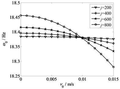
Fig. 5Relationship between tension and frequency
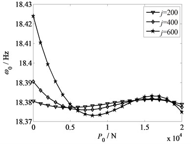
Fig. 5 shows the relationship curves between strip tension and frequency of strip with different values of rotational inertias, which are 200 kg·m2, 400 kg·m2 and 600 kg·m2, respectively. The torsional stiffness 9×10³ N·m/rad, the axial velocity 0.008 m/s. From Fig. 5, the vibration frequency decreases with the increase of the strip tension. When 5×10³ N, as long as the rotational inertia becomes larger, the frequency of strip gets stronger. Whereas, when 5×10³ N, the curves present fluctuation, then stabilize gradually. Thus, it follows that a smaller strip tension change results in a greater effect of frequency. Additionally, it is shown that the bigger the rotational inertia is, the faster the trend of curve declines. In other words, a further proof is given that a bigger variation of frequency caused by a greater rotational inertia.
Fig. 6 depicts the relationship curves between torsional stiffness of drive system and frequency of strip with different values of rotational inertias, which are 200 kg·m2, 400 kg·m2, 600 kg·m2, and 800 kg·m2, respectively. The strip tension 8×10³ N, the axial velocity 0.008 m/s. As can be seen from the Fig. 6, with the increase of the torsional stiffness, the curves show a uniform change, and the vibration frequency decreases gradually. And a larger rotational inertia leads to a larger downtrend of curve. The result shows that the boundary of strip is close to the clamped condition with the infinite increase of rotational inertia. Compared with a model of moving strip without main drive system, the overall frequency curves tend to be more stable. Moreover, the greater the torsional stiffness is, the smaller the rolling forces exerts, which reduces the vibration frequency of strip to some extent.
From the frequency-response curves in Figs. 4-6, a common feature can be found that a larger rotational inertia of roller gives rise to a greater variation tendency of frequency, which causes a more obvious vibration. In other words, a larger rotational inertia has a greater effect on the relationships from the influencing factors that is the axial velocity, strip tension and torsional stiffness to the frequency. Therefore, it is very important to select the appropriate rotational inertia of roller in the research and practice.
Fig. 7 illustrates the amplitude-frequency responses under the condition of different axial velocities: 2×10⁻³ m/s, 2×10⁻³ m/s, 10×10–3 m/s, 14×10–3 m/s and 18×10–3 m/s. The torsional stiffness 4×10⁴ N·m/rad, the strip tension 8×10³ N, and the rotational inertia 800 kg·m2. From Fig. 7, it is obtained that with the raise of the axial velocity, the vibration performance is transformed from sclerotic type into intenerate type gradually. When 10×10–3 m/s, with the increase of the amplitude, the vibration frequencies increase, and the hardening degree increases with the decreasing axial velocity. When 14×10–3 m/s, the curve shows a trending of decrease, namely, the vibration performance is intenerated type. That is, being oversized or excessively small of the axial velocity will cause the great influence of the amplitude on frequency.
Fig. 6Relationship between torsional stiffness and frequency
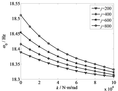
Fig. 7Amplitude-frequency response with different axial velocities
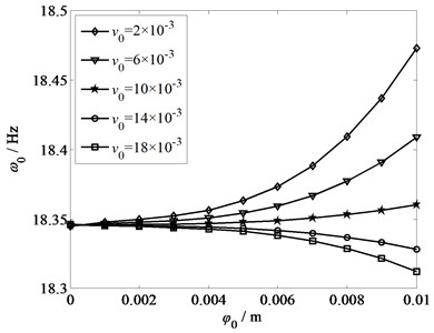
Fig. 8 demonstrates the amplitude-frequency responses under the condition of different strip tensions: 4×10³ N, 6×10³ N, 8×10³ N and 10×103 N. The torsional stiffness 4×10⁴ N·m/rad, the rotational inertia 800 kg·m2, and the axial velocity 0.01 m/s. In Fig. 8, with the increase of the amplitude, the vibration frequency increases, and the vibration performance keeps consistent. It also can be known that the changing of vibration frequency is small and stable under the condition of lower amplitude. However, at the point of amplitude 0.006, there is an intersection. After that, with the raise of the amplitude, the vibration frequency increases fast. That is to say, a smaller strip tension results in a larger variation range of the amplitude-frequency response. Based on the mechanics of vibration, the smaller the tensile force, the more unstable the system, thereby, it makes strip vibration quite strong.
Fig. 8Amplitude-frequency response with different strip tensions
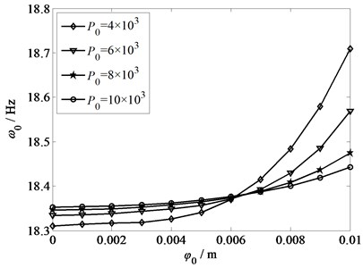
Fig. 9Amplitude-frequency response with different torsional stiffness
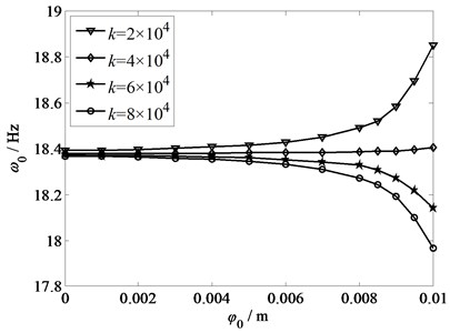
Fig. 9 displays the amplitude-frequency responses under the condition of different torsional stiffness: 2×10⁴ N·m/rad, 4×10⁴ N·m/rad, 6×10⁴ N·m/rad and 8×10⁴ N·m/rad. The rotational inertia 800 kg·m2, the strip tension 8×10³ N, and the axial velocity 0.01 m/s. From Fig. 9, as the torsional stiffness increases, the vibration performance changes from positive correlation to negative correlation gradually. When 4×10⁴ N·m/rad, the frequencies increase with the increasing amplitude, and the vibration performance shows positive correlation. Keep on increasing the size of torsional stiffness, the amplitude can be decreased, and the vibration performance shows negative correlation. Due to the above analysis, unsuitable size of the torsional stiffness will lead to inconsistent movement between rollers and strip, therefore, it leads to the torsional vibration of main drive system. Consequently, the torsional stiffness should be selected appropriately in practical design to reduce the rolling instability.
5. Conclusions
In this paper, the strip vibration coupled with torsional vibration of main drive system of rolling mill is investigated. It is given that the influences of the axial velocity, strip tension and torsional stiffness of drive system on vibration frequency of strip, in which all of the influencing factors are related to the rotational inertia of roller. A larger rotational inertia of roller gives rise to a greater changing trend of frequency, and leads to a more obvious vibration of strip. Moreover, the axial velocity, the strip tension and the torsional stiffness of drive system have also great influences on the amplitude-frequency characteristic of strip vibration. The changing trends of the amplitude-frequency response curves are accordantly increasing with the different strip tension, and a larger tension results in a smaller increasing gradient. Whereas, the amplitude-frequency characteristic of strip vibration will transform from sclerotic type into intenerate type with the increasing axial velocity or with the increasing torsional stiffness. Therefore, the analysis results of this paper show that the importance of choosing appropriate axial velocity, strip tension, torsional stiffness and rotational inertia on control and optimization of strip vibration of rolling mill.
References
-
Hou F. X., Zhang J., Cao J. G. Review of chatter studies in cold rolling. Journal of Iron and Steel Research, Vol. 19, Issue 10, 2007, p. 6-11, (in Chinese).
-
Wright J. Mill drive system to minimize torque amplification. Iron and Steel Engineer, Vol. 53, Issue 7, 1976, p. 56-60.
-
Fan X. B., Zang Y., Wang F., et al. Hot strip mill nonlinear torsional vibration with multi-stand coupling. Journal of Vibroengineering, Vol. 17, Issue 4, 2015, p. 1623-1633.
-
Moller R. H., Hoggart J. S. Periodic surface finish and torque effects during cold strip rolling. Journal of the Australian Institute of Metals, Vol. 12, Issue 2, 1967, p. 155-164.
-
Lawrence A. B., Thomas S. R. Winding reel involvement in temper mill chatter. Iron and Steel Engineer, Vol. 71, Issue 11, 1994, p. 27-29.
-
Swiatoniowski A., Bar A. Parametrical excitement vibration in tandem mills-mathematical model and its analysis. Journal of Materials Processing Technology, Vol. 134, Issue 2, 2003, p. 214-224.
-
Wang R. P., Peng Y., Zhang Y. Mechanism research of rolling mill coupled vibration. Journal of Mechanical Engineering, Vol. 49, Issue 12, 2013, p. 66-71, (in Chinese).
-
Sun J. L., Peng Y., Liu H. M. Dynamic characteristics of cold rolling mill and strip based on flatness and thickness control in rolling process. Journal of Central South University, Vol. 21, Issue 2, 2014, p. 567-576.
-
Wang Y., Xu F., Li Y. Dynamic modeling and coupling vibration analysis of hybrid systems consisting of strip, rolls and flexible supports. Journal of Vibration Engineering, Vol. 26, Issue 4, 2013, p. 599-607, (in Chinese).
-
Xu F., Li Y., Li L. F. Parametric vibration analysis for sheet metal and its supporting system. Mechanical Research and Application, Vol. 26, Issue 3, 2013, p. 27-30, (in Chinese).
-
Zou J. X., Xu L. J. Tandem Mill Vibration Control. Metallurgical Industry Press, Beijing, 1998, (in Chinese).
-
Gao C. Y., Du G. J., Feng Y., et al. Nonlinear vibration analysis of moving strip with inertial boundary condition. Mathematical Problems in Engineering. Vol. 8, Issue 2015, 2015, p. 1-9.
-
Gao C. Y., Du G. J., Li J. X. Numerical analysis on torsional vibration of main driving system of rolling mill with strip steel. Journal of Yanshan University, Vol. 40, Issue 1, 2016, p. 58-65, (in Chinese).
-
Chen L. Q., Yang X. D. Steady-state response of axially moving viscoelastic beam with pulsating speed: comparison of two nonliner models. International Journal of Solids and Structures, Vol. 42, 2005, p. 10-15.
-
Du G. J., Ma J. Q. Nonlinear vibration and buckling of circular sandwich plate under complex load. Applied Mathematics and Mechanics, Vol. 28, Issue 8, 2007, p. 1081-1091.
-
Shen Y. Z., Liu H. M., Xiong J., and et al. Analysis of chaotic behavior of the main drive system with clearance of a heavey plate mill. Engineering Mechanics, Vol. 27, Issue 7, 2010, p. 232-236, (in Chinese).
-
Han S. M., Benaroya H., Wei T. Dynamics of transversely vibrating beam using four engineering theories. Journal of Sound and Vibration, Vol. 225, Issue 5, 1999, p. 935-988.
-
Huang J. L., Chen S. H. Study on nonlinear vibration of an axially moving beam with coupled transverse and longitudinal motions. Journal of Vibration and Shock, Vol. 30, Issue 8, 2011, p. 24-27, 50, (in Chinese).
Cited by
About this article

This research was supported in part by Natural Science Foundation of Hebei Province (E2017203115), in part by Key Project of Science and Technology of Hebei Higher School (No. ZD2015077), and in part by Doctor Foundation of Yanshan University (No. B992).
