Abstract
In view of the torsional vibration problem of the main drive system of the F5 rolling mill in a steel plant, two sets of torque monitoring sensors were installed on the cross universal joint shaft on site. Through online monitoring, it is found that the torsional vibration frequency of the cross universal joint shaft is twice the rotational frequency of the drive system, and the vibration amplitude of the upper shaft is greater than that of the lower shaft. Considering the influence of the inclination angle of the cross universal joint shaft, the transmission system can be simplified as a multi-body dynamic model of a five-inertia spring-mass system. Combined with the effect of the rolling torque of the strip and the electromagnetic torque of the main motor on the main drive system, a simulation model considering multi-physics coupled torsional vibration was established MATLAB/Simulink. The simulation shows that the torsional vibration frequency changes linearly with the rolling speed, which is always twice the rotational frequency of the transmission system, and the vibration amplitude also changes with the rolling speed, consistent with the field test results. As the diameter of the work roll increases, the angle of inclination of the universal joint shaft decreases, and the value of the torsional amplitude of the system also decreases. When the inclination angle is not considered at all, the torsional vibration of the system disappears, it shows that the inclination angle of the cross universal joint shaft is the root cause of the double rotational frequency torsional vibration of the main drive system. Since the inclination of the cross universal joint cannot be eliminated, the simulation results show that the torsional vibration of the transmission system can be effectively reduced by using large-diameter work rolls and reducing the stiffness of the upper cross universal joint while increasing the stiffness of the lower universal joint. When the lower shaft stiffness increases to 1.3 times, the upper shaft stiffness decreases to 0.8 times, and the work roll diameter is 425 mm, the torsional vibration amplitude of the upper connecting shaft decreases by 22.3 % at the rolling speed of 1200 m/min.
Highlights
- In this paper, a rolling torque model is established to reveal the mechanism of coupled torsional vibration of strip steel and transmission system.
- At the same time, the nonlinear torsional vibration model of the transmission system considering the included angle of the universal joint shaft is established, and the influence of the included angle of the shaft system on the transmission system is deeply studied.
- Again, the effect of suppressing torsional vibration is proposed by using cross universal joints with asymmetric stiffness.
1. Introduction
Mill vibration is an industry-wide problem worldwide. Due to the characteristics of high technical integration and complex structure, the rolling mill system makes the rolling vibration mechanism and vibration forms various. The research on the rolling mill vibration has been extensively investigated.
Zhong et al. [1] found that the vibration phenomenon of the rolling mill is the result of the multi-physics coupling effect in the rolling mill system. Yan et al. [2] determined the vibration nature of the rolling mill to be electro-mechanical-hydraulic coupled vibration through vibration testing of the rolling mill on site, and effectively suppressed the rolling mill vibration by adjusting the parameters of the rolling mill. Gao et al. [3] studied the self-excited vibration of the tandem cold rolling mill, and derived the rolling speed threshold for the self-excited vibration of the cold rolling mill based on the structural parameters of the rolling mill, rolling process parameters and control parameters. Xiong et al. [4] found that the design defects of the thickness control system of the rolling mill can induce the self-excited vibration of the vertical system of the rolling mill under certain conditions. Wei et al [5] pointed out that rolling lubrication is an important factor leading to the self-excited vibration of the vertical system of the cold rolling mill. And the rolling lubrication can cause self-excited vibration of the main drive system of the rolling mill [6]. Zhang et al. [7] found that under the dual excitation of electrical harmonics and rolling force harmonics, the rolling mill drive system will produce various vibration characteristics such as sub-harmonic, super-harmonic and combined resonance. Gao et al. [8] studied the influence of parameters such as rolling speed, transmission stiffness, strip tension on the coupling vibration of the continuous rolling mill transmission system. Yan et al. [9] deduced that the torsional vibration of the universal joint shaft in the main drive system of the rolling mill would cause bending vibration. Wang et al. [10] concluded that due to the existence of the inclination angle of the universal joint shaft in the rolling mill transmission system, part of the torsional vibration is converted into bending vibration, and then the coupling relationship between the horizontal vibration and the vertical vibration of the rolling mill is formed. Shi et al. [11] established a nonlinear equation of torsional vibration considering the influence of the inclination angle of the rolling mill drive joint shaft and roll gap friction on the torsional vibration of the transmission system. B. Porter et al. [12] studied the nonlinear torsional vibration problem of shafting with Hooke hinges, and expounded the relationship between vibration frequency and rotational speed. Bharti et al. [13] analyzed the Z-shaped electromechanical coupling transmission system with a cross universal joint shaft and found that the system will experience resonance capture and escape at different speeds. Feng et al. [14] analyzed the torsional jump phenomenon and the dynamic bifurcation phenomenon of the Hooke hinge shaft system. There are also many studies in the literatures that study the torsional vibration stability of shafting systems involving Hooke hinges [15-18].
Current research on rolling vibration has solved many practical problems in the field, and also enriched the theoretical results of rolling mill vibration. However, there is still has almost no relevant research to fully explain and solve the torsional vibration problem of the F5 cold rolling mill transmission system in a steel plant. In this work, we combined the on-site vibration test with simulation models, found out the rules of the torsional vibration of F5 cold rolling mill transmission system, and revealed that that the inclination angle of the cross universal joint shaft, easily to be neglected, is the main cause for the double rotational frequency torsional vibration. Furthermore, we found that the torsional vibration was effectively reduced by increasing the diameter of the work rolls and by using asymmetrical stiffness cross universal joints.
2. Field test of rolling mill main drive’s torsional vibration
The cold tandem rolling mill of a steel plant consisted of five stands of F1-F5 rolling mills, and the maximum rolling speed was designed to be 1200 m/min. The F5 rolling mill possessed the highest speed, accompanied with the most serious vibration problem. The structure of the transmission system of the F5 rolling mill is shown in Fig. 1.
The rotor shaft of the motor was connected with the lower shaft of the gear seat through the arc tooth joint. The arc tooth joint was equipped with a safety pin. The lower shaft of the gear shaft and the upper were meshed with helical gears with the same number of teeth. The upper and lower shafts of the gear seat connected with the upper and lower work rolls through the two cross universal joint shafts, and the intermediate shaft of the universal joint shaft was composed of an inner and an outer shaft with sliding splines. The work rolls, intermediate rolls and backup rolls were driven by friction on the roll surface.
A self-made wireless torque tester was installed on the upper and lower cross universal joint shafts on site to monitor the torque of the universal joint shaft online, as shown in Fig. 2(a). The paint and oil stains on the surface of the connecting shaft were cleaned first, and then was grind to be smooth and flat. Subsequently, a special strain gauge was pasted on the surface of the connecting shaft for torque testing, as shown in Fig. 2(b), and finally the unit for torque signal test and processing was installed on the shaft device. The system structure of the wireless torque tester is shown in Fig. 2(c). The list of torque tester equipments is shown in Table 1.
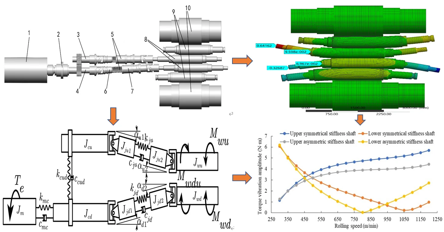
Fig. 1Mechanical structure model of F5 cold rolling mill transmission system: 1 – main motor; 2 – curved tooth catch; 3 – gear seat upper shaft; 4 – gear seat lower shaft; 5 – cross universal joint; 6 – inner shaft; 7 – external shaft; 8 – work roll; 9 – intermediate roll; 10 – back-up roller
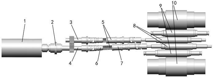
Fig. 2Cross universal joint torque field test picture. Photographer: Xingdou Jia, Shooting time: December 19, 2020, Location: Beijing Shougang Qian’an Iron and Steel Company, Qian’an City, Hebei Province, China (Photos can be published freely without copyright conflict)
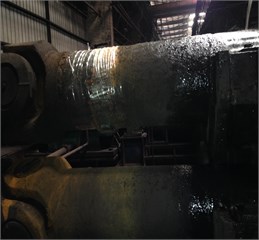
a) Wireless torque tester
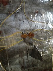
b) Special strain gauge for torque test
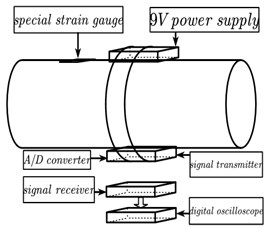
c) System structure of wireless torque tester
Table 1Equipment list of torque tester
Equipment name | Manufacturer and product model | Remarks |
Special strain gauge | CHENGTEC / BFH120-3BA-Q30 | Sensitivity coefficient: 2.0±1 % Ω/με |
Signal transmitter and receiver | FEASYCOM / FSC-BT986 | |
Digital oscilloscope | UNI-T / UTD2072CL | Sampling frequency: 1000 Hz |
Fig. 3On-site rolling speed operation diagram
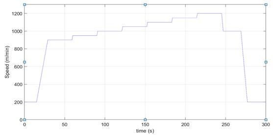
The rolling mill with a diameter of 406.5 mm work rolls was used to roll SPCC strips with a width of 1050 mm, rolling speed was continuously increased from 900 m/min to 1200 m/min, as shown in Fig. 3, and the torque vibration of the two universal joint shafts was recorded at each speed, as shown in Fig. 4-6.
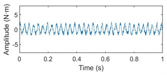
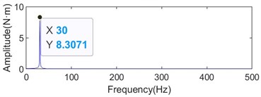
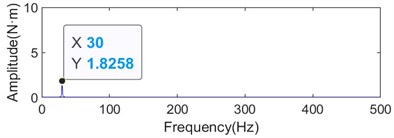
Fig. 4Torque vibration time-frequency diagram of upper and lower cross universal joint shafts at 1200 m/min rolling speed
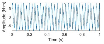
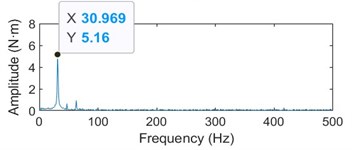
a) Vibration spectrum diagram of upper shaft torque test
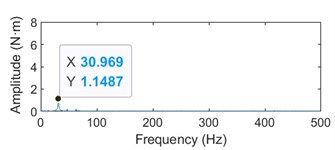
b) Vibration spectrum diagram of lower shaft torque test
Fig. 5Variation diagram of torque vibration frequency of cross universal joint shaft with rolling speed
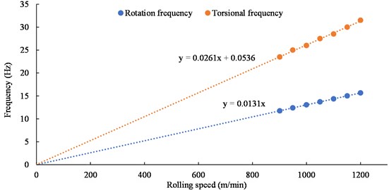
Fig. 6Variation diagram of torque vibration amplitude of the upper and lower cross universal joint shafts with the rolling speed
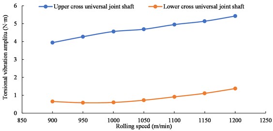
It can be seen from Figs. 4-6 that under the rolling speed of 1200 m/min, the rotational frequency of the transmission system is 15.66 Hz, and the torsional vibration frequency of the upper and lower shafts is 30.969 Hz, which is very similar to the double rotational frequency, and is the same at other speeds. The torsional vibration amplitude value of the upper shaft is obviously larger than that of the lower shaft, and both increase with the increase of rolling speed.
3. Establishment of the main drive model of the rolling mill
3.1. Establishment of rolling torque model
During the rolling process, the rolling torque between the work roll and the strip can be expressed as Eq. (1):
here and are the friction forces in the back slip and the forward slip areas, respectively, which can be expressed as Eqs. (2) and (3):
where is work roll radius (mm); is the friction coefficient between the work roll and the strip; represents the average unit positive pressure on the surface of the strip steel in the deformation zone (Mpa); denotes strip width (mm); is the strip bite angle (°), which can be expressed as Eq (4):
where represents the deformed thickness of the strip (mm); is the neutral angle of the deformation zone (°), which can be expressed as Eq (5):
where represents the linear speed of the work roll (m/min); represents the strip speed at the exit of the deformation zone (m/min); represents the thickness of the strip at the exit of the deformation zone (mm).
By substituting Eqs. (2)-(5) into Eq (1), can be obtained as follows:
When the work roll speed increases and decreases in a wide range, the strip speed at the outlet of the deformation zone will increase or decrease synchronously to ensure that the rolling torque is basically unchanged. When fluctuates in a small range, remains basically constant.
The linear speed of the work roll can be expressed as:
where, is the stable linear speed component of the work roll; is the linear velocity fluctuation component; is the angular velocity of the work roll; is the stable component of the work roll angular velocity; is the fluctuation component of the work roll angular velocity.
Since the magnitude of is small, Eq. (8) is obtained by first-order expansion of torque at speed according to Taylor’s formula:
Then the rolling torques of the upper and lower work rolls are respectively expressed by Eqs. (9) and (10):
where, , here represents the rolling torque fluctuation coefficient.
It can be seen from Eqs. (9) and (10) that the fluctuation amount of rolling torque changes with the fluctuation of rolling speed when rolling in steady state. However, the change of the rotational speed of the work roll not only causes the torque fluctuation of its own roll, but also the torque fluctuation of the other roll. That is, an additional rolling torque is generated. When the speed of the upper and lower work rolls is different, the high-speed roll becomes the driving roll, and the low-speed roll becomes the driven roll, and the driving roll transmits the torque to the driven roll through the strip steel, so that the phenomenon of rubbing occurs. The greater the speed difference, the greater the rolling torque, which can be expressed as Eq. (11):
where, represents the influence coefficient of rolling torque fluctuation between the upper and lower work rolls, and its magnitude is equivalent to . Therefore, the torques experienced by the work rolls are , , and . All the parameter values in the formula are shown in Table 2.
Table 2Strip rolling parameter values
Parameter | Value | Unit | Parameter | Value | Unit |
0.05 | 0.05 | mm | |||
900 | Mpa | 1200 | m/min | ||
1000 | mm | 1210 | m/min | ||
192.5-212.5 | mm | 0.5 | mm |
3.2. Establishment of the multi-body dynamics model of the main drive system
According to the structural rigidity of the mechanical parts of the main drive system of the rolling mill, the arc-shaped toothed joint, the meshing gear and the sliding spline of the cross universal joint shaft are simplified as torsion springs and dampers, and other parts are simplified as the centralized rotational inertia body. The transmission system is simplified to the mass-spring torsional vibration model shown in Fig. 7, where is the moment of inertia of the motor rotor shaft; is the moment of inertia of the lower shaft of the gear seat; is the moment of inertia of the upper shaft on the gear seat; is the moment of inertia of the inner shaft of the lower universal joint shaft; is the moment of inertia of the outer shaft of the lower universal joint shaft; is the moment of inertia of the inner shaft of the upper universal joint shaft; is the moment of inertia of the outer shaft of the upper universal joint; is the moment of inertia of the lower work roll; is the moment of inertia of the upper work roll; and are the stiffness and damping of the arc tooth joint, respectively; and are the meshing stiffness and damping of the helical gear of the gear seat, respectively; and are the stiffness and damping of the sliding spline of the lower universal joint shaft, respectively; and are the stiffness and damping of the upper universal joint shaft sliding spline, respectively; is the angle between the lower universal joint shaft and the lower shaft of the gear seat; is the angle between the lower universal joint shaft and the lower work roll; is the angle between the upper universal joint shaft and the upper shaft of the gear seat; a is the angle between the upper universal joint shaft and the upper work roll.
Fig. 7Model diagram of spring-mass torsional vibration of the F5 rolling mill main drive system
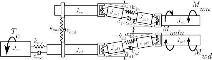
Here,, and represent the angular displacement, angular velocity and angular acceleration of the rotor shaft of the motor, respectively; , and represent the angular displacement, angular velocity and angular acceleration of the lower shaft on the gear seat, respectively; , and represent the angular displacement, angular velocity and angular acceleration of the upper shaft on the gear seat, respectively; , and represent the angular displacement, angular velocity and angular acceleration of the lower work roll, respectively; , and represent the angular displacement, angular velocity and angular acceleration of the upper work roll, respectively; and represent the angular velocity of the inner and outer shafts of the upper universal joint shaft, respectively; and represent the angular velocities of the inner and outer shafts of the lower universal joint shaft, respectively;
According to the kinematic analysis of each component of the universal joint shaft, the relationship between the angular velocity of the inner shaft of the universal joint shaft and the angular velocity of the gearbox shaft can be obtained as shown in Eqs. (12) and (13) [19]:
In the same way, the relationship between the angular velocity of the outer shaft of the universal joint shaft and the angular velocity of the roll is shown in Eqs. (14) and (15):
where, and are set in advance as the relative torsion angle and angular velocity of the inner and outer shafts of the upper universal joint shaft; let and be the relative torsion angle and angular velocity of the inner and outer shafts of the lower universal joint shaft, respectively.
Then there are Eqs. (16) and (17):
The torques between the inner and outer shafts of the upper and lower universal joint shafts are expressed as Eqs. (18) and (19), respectively:
The action directions of and are the axial directions of the upper and lower universal joint shafts, respectively.
According to the dynamic analysis of the cross universal joint transmission, the torque output by the upper shaft of the gear seat at the joint end along its own axis is expressed as [21]:
The torque on the drive side of the upper work roll along its axis is expressed as:
The torque output from the lower shaft of the gear seat along its own axis at the connecting end is expressed as:
The torque on the drive side of the lower work roll along its axis is expressed as:
On the other hand, the rotational kinetic energy of the inner shaft of the universal joint shaft is expressed as:
Then, the equivalent moment of inertia of the inner shaft of the upper universal joint shaft converted from its own axis to the axis of the upper shaft of the gear shaft is expressed as:
In the same way, the equivalent moment of inertia of the outer shaft of the upper universal joint shaft converted from its own axis to the axis of the upper work roll is expressed as:
The equivalent moment of inertia of the inner shaft of the lower universal joint shaft converted from its own axis to the axis of the lower shaft of the gear seat is expressed as:
The equivalent moment of inertia of the outer shaft of the lower universal joint shaft converted from its own axis to the axis of the lower work roll is expressed as:
As mentioned above, the multi-body dynamics equations of the main drive mechanical system of the F5 rolling mill can be expressed as Eqs. (1)-(5):
The data in the following Table 3 are obtained after calculation according to the field equipment parameters. The structural damping ratio of the main drive system is 0.01.
The values of , , and were determined by the diameter of the work rolls, the size of shifting rolls and bending rolls. The diameter of the work rolls ranges from 385 mm to 425 mm. Considering the need to control the shape of the strip, shifting and bending operations are required for the intermediate rolls and work rolls during the rolling process. When the rolls are in the initial position, the upper and lower work rolls and the intermediate rolls are aligned, and the axes of the work rolls and the gear shafts are parallel, there is ; When the rolls are in the tandem state, the upper work rolls move to the drive side, and the lower work rolls move to the operation side, as shown in Fig. 1, then .
Table 3F5 rolling mill main drive torsional vibration model parameter table
Name | Value | Unit | Name | Value | Unit |
162 | kg·m² | 40.9-54.08 | kg·m² | ||
53.86 | kg·m² | 40.9-54.08 | kg·m² | ||
25.2 | kg·m² | 7690000 | N·m/rad | ||
21 | kg·m² | 5170000 | N·m/rad | ||
21 | kg·m² | 3580000 | N·m/rad | ||
31.5 | kg·m² | 3580000 | N·m/rad | ||
31.5 | kg·m² |
In the normal rolling state, the strip shape control method includes both shifting and bending rolls. According to the actual working conditions, a bending force of 220 kN is applied to the bearing seats on both sides of the intermediate roll, and a bending force of 180 kN is applied to the bearing seats on both sides of the work roll. Using the statics module of the ANSYS/Workbench finite element software, the deformation cloud diagram of the roll system is obtained as shown in Fig. 8.
According to the deformation in the figure, the bending angle of the upper work roll on the driving side can be calculated to be 0.03°, and the bending angle of the lower work roll is 0.015°. There are 0.03° and 0.015°. According to the size and spatial position of the field equipment, the statistics of the angle between the cross universal joint shaft and the gear shaft and the work roll are shown in Table 4 below when using different work roll diameters.
Fig. 8Deformation cloud diagram of six-high cold rolling mill’s rolls under the action of bending force
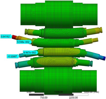
Table 4Statistics of the angle between the cross universal joint shaft, the gear shaft and the work roll (°)
Condition | initial state | Shifting roll | Shifting and bending roll | ||||||||||
Name | |||||||||||||
Work roll diameter | 385 mm | 1.24 | 1.24 | 1.24 | 1.24 | 1.298 | 1.298 | 1.187 | 1.187 | 1.298 | 1.268 | 1.187 | 1.172 |
400 mm | 1.112 | 1.112 | 1.112 | 1.112 | 1.16 | 1.16 | 1.064 | 1.064 | 1.16 | 1.13 | 1.064 | 1.049 | |
425 mm | 0.898 | 0.898 | 0.898 | 0.898 | 0.94 | 0.94 | 0.859 | 0.859 | 0.94 | 0.91 | 0.859 | 0.844 | |
3.3. Establishment of the model of the main motor speed control system
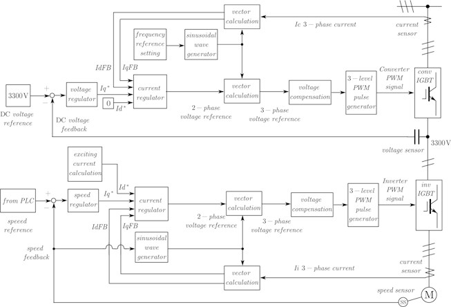
The main drive system of the rolling mill is driven by an asynchronous 3300 kw AC motor. The motor is driven by a three-level dual PWM inverter. The inverter adopts the rotor magnetic field oriented asynchronous motor vector control technology. The block diagram of the control system of the motor is shown in Fig. 9.
Fig. 9The vector control schematic of the F5 cold rolling mill’s main motor
4. Establishment of MATLAB/Simulink simulation model for coupling torsional vibration of main drive system of rolling mill
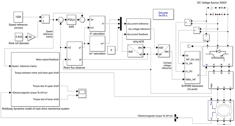
According to the rolling torque model between the strip and the work roll, the multi-body dynamics model of the mechanical and the electrical control system model of the main motor, a MATLAB/Simulink simulation model of the coupled torsional vibration of the main drive of the rolling mill is established, as shown in Fig. 10.
Fig. 10Simulation diagram of coupling model of F5 rolling mill’s main drive system
5. Torsional vibration simulation of rolling mill main drive system
5.1. Influence of work roll diameter and rolling speed on torsional vibration
The diameters of the work rolls are 385 mm, 405 mm and 425 mm, respectively. The rolling speed is set at 50 m/min intervals, starting from 300 m/min and increasing to the highest speed of 1200 m/min. The torque vibration frequency of the upper and lower shafts at each speed moment is counted. The relationship between the torque vibration frequency of the upper and lower shafts and the rolling speed is obtained as shown in Fig. 11.
Fig. 11The relationship between the torsional vibration frequency of the shaft connection and the rolling speed for different work roll diameters
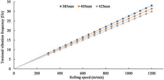
It can be seen from Fig. 11 that the torque vibration frequency of the upper and lower shafts is always the same regardless of the roll diameter, and has a linear relationship with the rolling speed. The vibration frequency value is exactly twice the rotational frequency of the drive train at that speed, The vibration frequency value is exactly twice the rotating frequency of the transmission at this speed, which is basically consistent with the test result.
At different rolling speeds, the torque vibration amplitudes of the upper and lower shafts were calculated when the diameters of the work rolls were 385 mm, 405 mm and 425 mm, respectively. The relationship between the torque vibration amplitude of the upper and lower shafts and the rolling speed is obtained as shown in Fig. 12.
Fig. 12The relationship between the torque vibration amplitude of the upper and lower shafts with the rolling speed for different work roll diameters
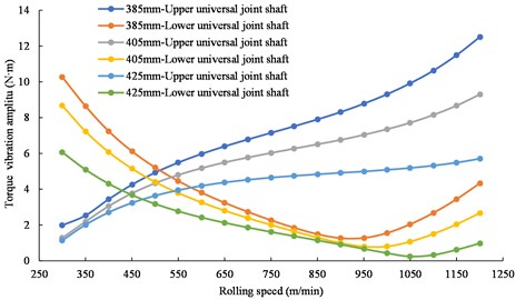
Fig. 12 shows that with the increasing the rolling speed, the torque vibration amplitude of the upper shaft gradually increases, and the torque vibration amplitude of the lower shaft first decreases and then increases.
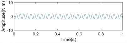
When the rolling speed is greater than 550 m/min, the torque vibration amplitude of the upper shaft is larger than that of the lower shaft, which also conforms to the test results. With assuming a certain diameter of the work roll of 405 mm and the rolling speed of 1150 m/min, the torque vibration spectrum of the upper and lower shafts is shown in Fig. 13.
Fig. 13Time-frequency diagram of torque fluctuation of upper and lower shafts when the work roll diameter is 405 mm and the rolling speed is 1150 m/min
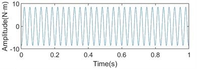
a) Spectrum diagram of torque fluctuation of upper shaft
b) Spectrum diagram of torque fluctuation of lower shaft
It can be seen from Figs. 12 and 13 that the torque vibration amplitude of the upper shaft is significantly larger than that of the lower shaft. In addition, under the same rolling speed, with the increase of the diameter of the work roll, the torque vibration amplitude of the upper and lower shafts showed a decreasing trend. The above phenomenon is basically consistent with the field test signal, indicating that the built model is more consistent with the field equipment.
5.2. Influence of strip shape control on torsional vibration
The diameter of the work rolls above mentioned has a significant effect on the torsional vibration of the system. In addition to the different moments of inertia of work rolls with different diameters, the angle between the connecting shaft and the work roll and the gear shaft is also different. The following uses different strip shape control methods to change the angle between the connecting shaft and the work roll and the gear shaft to study the influence on the torsional vibration of the transmission system. When the rolling speed is 1200 m/min, the work rolls with a diameter of 425 mm are in the original state, the shifting state and the shifting-bending state, respectively. The torque vibration amplitudes of the two connecting shafts are shown in Fig. 14.
Fig. 14The torque fluctuation amplitude of the upper and lower shafts under different shape control conditions
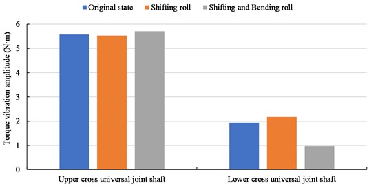
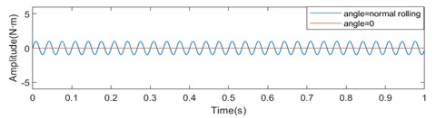
The torsional vibration amplitude of the connecting shaft is not only related to the rolling speed, but also related to the angle between the connecting shaft and the work roll and the gear shaft. The smaller the angle, the smaller the vibration amplitude. Set , and to zero and the values in the state of shifting-bending roll, respectively. The torque fluctuation of the upper and lower shafts is obtained from the simulation, as shown in Fig. 15.
Fig. 15The torsional vibration waveforms of the upper and lower connecting shafts when the connecting shaft inclination is normal and zero
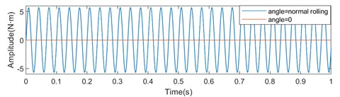
a) Torque vibration diagram of upper shaft
b) Torque vibration diagram of lower shaft
When the angles of the connecting shaft and the work roll and gear shaft are not considered, the torque vibration amplitudes of the upper and lower connecting shafts are both 0. It can be seen that the angle between the connecting shaft and the work roll and the gear shaft is the root cause of the torsional vibration of the transmission system.
5.3. The effect of joint stiffness on torsional vibration
Due to the requirements of strip shape control and the mechanical structural parameters of the rolling mill, the inclination angle of the cross universal joint must exist and cannot be ignored. For the main drive mechanical system of the rolling mill that has been built, the system characteristics can only be changed by replacing the cross universal joint shafts with different stiffness values produced by different manufacturers. According to the existing equipment parameters, the stiffness of the upper and lower shafts was increased to 1.3 times separately, and the 425 mm diameter work roll was used for simulation at a rolling speed of 1200 m/min. The torque vibration amplitude of the upper and lower shafts obtained by simulated is compared with the results under the original joint stiffness, as shown in Fig. 16.
Fig. 16Torque fluctuation amplitudes of upper and lower shafts with different stiffnesses
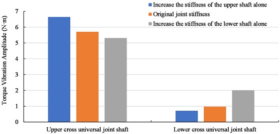
As shown in Fig. 16, increasing the stiffness of the upper shaft alone will increase the torque vibration amplitude of the upper shaft while decrease the torque vibration amplitude of the lower shaft, which further increases the vibration amplitude difference between the upper and lower shafts. It is not conducive to the operation of the transmission system. When the stiffness of the lower connecting shaft is increased alone, the change trend of the torque vibration amplitude of the connecting shaft is opposite. Therefore, it can be considered that reducing the stiffness of the upper connecting shaft and increasing the stiffness of the lower connecting shaft at the same time, using shafts with asymmetric stiffness will reduce the vibration of the transmission system and be more conducive to the operation of the transmission system than that with symmetrical stiffness of the same stiffness value. The stiffness of the lower shaft is increased to 1.3 times, and the stiffness of the upper shaft is reduced to 0.8 times, and the torque vibration amplitudes of the upper and lower shafts are compared under asymmetric stiffness and symmetric stiffness at different speeds. The results are shown in Fig. 17.
Fig. 17The relationship between the torque vibration amplitude and the rolling speed of the upper and lower shafts with asymmetric and symmetric stiffness
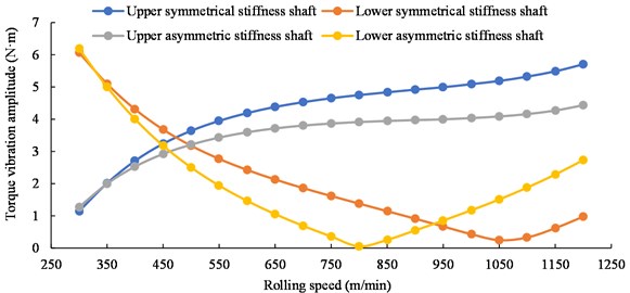
It can be concluded that the torque vibration amplitude of the upper connection shaft is reduced in the full speed range, and the torque vibration amplitude of the lower connection shaft is reduced in the speed range less than 950 m/min, and the torque vibration amplitude of the upper connection shaft is reduced in the speed range of less than 950 m/min, and the increments are also relatively low. Therefore, it is more reasonable to use shafts with asymmetric stiffness.
6. Conclusions
By monitoring the torsional vibration of the transmission system of the F5 cold rolling mill in a steel plant, the following researches are carried out in theory.
1) The rolling torque model between the strip and the roll and the multi-body dynamics model of the main drive mechanical system of the rolling mill considering the inclination angle of the cross universal joint shaft are established. According to the speed control method of the main motor, combined with the rolling model and the multi-body dynamics model, a multi-physics coupled torsional vibration simulation model of the main drive system of the rolling mill based on MATLAB/Simulink is established.
2) It is found through simulation that in the case of no external excitation during the rolling process, the main drive system will generate torsional vibration whose frequency is twice the system rotational frequency. The torsional vibration frequency has a linear relationship with the rolling speed, and the torsional amplitude value decreases with the increase of the diameter of the work roll.
3) By studying the influence of the inclination of the cross universal joint on the torsional vibration, it is found that the smaller the inclination of the cross universal joint, the weaker the torsional vibration; when the inclination angle is completely ignored, the torsional vibration disappears. It shows that the inclination of the universal joint shaft is the root cause of the double rotational frequency torsional vibration of the system.
4) When studying the effect of the stiffness of the cross universal joint on the torsional vibration of the system, it is found that by increasing the stiffness of the lower cross universal joint and reducing that of the upper cross universal joint, the use of asymmetrical stiffness shafts is more beneficial to reduce the torsional vibration of the main drive system than the use of symmetrical stiffnesses shafts with exactly the same stiffness value. In a word, in the actual production process, the use of large-diameter work rolls and asymmetric stiffness joint shafts can effectively reduce the torsional amplitude value of the system.
References
-
J. Zhong and H. P. Tang, “Several vibration problems of high-speed rolling mill – research on coupling dynamics of complex electromechanical system,” (in Chinese), Journal of Vibration, Measurement &Diagnosis, Vol. 22, No. 1, pp. 3–10, 2002, https://doi.org/10.3969/j.issn.1004-6801.2002.01.001
-
X. Yan, “Machinery-electric-hydraulic coupling vibration control of hot continuous rolling mills,” (in Chinese), Journal of Mechanical Engineering, Vol. 47, No. 17, p. 61, 2011, https://doi.org/10.3901/jme.2011.17.061
-
Z.-Y. Gao, Y. Liu, Q.-D. Zhang, M.-L. Liao, and B. Tian, “Chatter model with structure-process-control coupled and stability analyses in the cold rolling system,” Mechanical Systems and Signal Processing, Vol. 140, p. 106692, Jun. 2020, https://doi.org/10.1016/j.ymssp.2020.106692
-
S. B. Xiong et al., “Rolling mill self-excited vibration diagnosis and structural dynamics modification,” (in Chinese), Chinese Journal of mechanical engineering, Vol. 41, No. 7, pp. 147–151, 2005, https://doi.org/10.3321/j.issn:0577-6686.2005.07.027
-
L. Q. Wei et al., “Influence of rolling lubrication on self-excited vibration in 1420 continuous cold rolling mill,” (in Chinese), Journal of Iron and Steel Research, Vol. 18, No. 2, pp. 28–31, 2006, https://doi.org/10.3321/j.issn:1001-0963.2006.02.007
-
C. Chen and Y. R. Li, “Influence of rolling lubrication on the self-excited vibration of rolling mill main drive system,” (in Chinese), Journal of Vibration and Shock, Vol. 34, No. 16, pp. 161–165, 2015, https://doi.org/10.13465/j.cnki.jvs.2015.16.027
-
Y. Zhang, “Research on torsional vibration of main drive system under multi-source excitation in CSP rolling mill,” (in Chinese), Journal of Mechanical Engineering, Vol. 53, No. 10, p. 34, 2017, https://doi.org/10.3901/jme.2017.10.034
-
C. Gao, G. Du, R. Li, and X. Guo, “An analysis on strip vibration coupled with torsional vibration of main drive system of rolling mill,” Journal of Vibroengineering, Vol. 19, No. 8, pp. 5679–5690, Dec. 2017, https://doi.org/10.21595/jve.2017.18216
-
X. Q. Yan et al., “Coupling of lateral and torsional vibration for the spindle of a CSP mill,” (in Chinese), Journal of University of Science and Technology Beijing, Vol. 30, No. 10, pp. 1158–1162, 2008, https://doi.org/10.3321/j.issn:1001-053x.2008.10.015
-
H. Wang et al., “Impact study of the hot continuous rolling mill vibration on universal shaft inclination angle,” (in Chinese), Metallurgical Equipment, Vol. 210, pp. 14–18, 2014, https://doi.org/10.3969/j.issn.1001-1269.2014.02.004
-
P. Shi, J. Li, D. Zhao, B. Liu, and D. Han, “Nonlinear torsional vibration dynamics of rolling mill’s drive system under spindle angle parametric excitation,” in 2012 10th World Congress on Intelligent Control and Automation (WCICA 2012), pp. 3091–3095, Jul. 2012, https://doi.org/10.1109/wcica.2012.6358403
-
B. Porter and R. W. Gregory, “Non-linear torsional oscillation of a system incorporating a Hooke’s joint,” Journal of Mechanical Engineering Science, Vol. 5, No. 2, pp. 191–209, Jun. 1963, https://doi.org/10.1243/jmes_jour_1963_005_026_02
-
S. K. Bharti and A. K. Samantaray, “Resonant capture and Sommerfeld effect due to torsional vibrations in a double Cardan joint driveline,” Communications in Nonlinear Science and Numerical Simulation, Vol. 97, p. 105728, Jun. 2021, https://doi.org/10.1016/j.cnsns.2021.105728
-
C. L. Feng, Y. Y. Zhu, and S. Wang, “Super-harmonic resonance analysis on torsional vibration of misaligned rotor driven by universal joint,” in Applied Mechanics and Materials, Vol. 26-28, pp. 1226–1231, Jun. 2010, https://doi.org/10.4028/www.scientific.net/amm.26-28.1226
-
G. Bulut, “Dynamic stability analysis of torsional vibrations of a shaft system connected by a Hook’׳s joint through a continuous system model,” Journal of Sound and Vibration, Vol. 333, No. 16, pp. 3691–3701, Aug. 2014, https://doi.org/10.1016/j.jsv.2014.03.022
-
A. J. Mazzei, “Passage through resonance in a universal joint driveline system,” Journal of Vibration and Control, Vol. 17, No. 5, pp. 667–677, Apr. 2011, https://doi.org/10.1177/1077546309346233
-
Martin Zajicek and Jan Dupal, “Analytic solution of simplified Cardan’s shaft model,” Applied and Computational Mechanics, Vol. 8, No. 2, pp. 215–228, Dec. 2014.
-
F. Vesali, M. A. Rezvani, and M. Kashfi, “Dynamics of universal joints, its failures and some propositions for practically improving its performance and life expectancy,” Journal of Mechanical Science and Technology, Vol. 26, No. 8, pp. 2439–2449, Aug. 2012, https://doi.org/10.1007/s12206-012-0622-1
About this article

The authors have not disclosed any funding.
The datasets generated during and/or analyzed during the current study are available from the corresponding author on reasonable request.
The authors declare that they have no conflict of interest.
