Abstract
Flip-flow screen with crankshaft-link structure (FFSCLS) is effective for screening of high-water and fine materials. In this paper, a dynamic model governing the vibration and mechanical characteristics of the FFSCLS is proposed. In addition, the motion trajectory and vibration data of the FFSCLS were investigated by MATLAB/Simulink method. The results show that the MATLAB/Simulink method can fully describe the vibration characteristics of the FFSCLS with the maximum deviation within 6.71 % between experiment results. The mechanical characteristics of the FFSCLS were systematically studied by automatic dynamic simulation analysis using the ADMAS software. The MBD simulation results indicated that the resultant forces of the inner and outer screen boxes are always equal to 0. Moreover, the rotational speed of the crankshaft, the stiffness coefficient of the guild springs and rubber springs determined the mechanical characteristics of the flip-flow screen, and these parameters should be optimized. This work is helpful for the understanding of the combined effects of parameters and provides essential references for optimal design and efficient operation of a flip-flow screen with crank-link structure.
Highlights
- The mechanical and dynamics model of a novel compound dry separator was proposed.
- The dynamics analysis of the NCDS was performed by means of MBD.
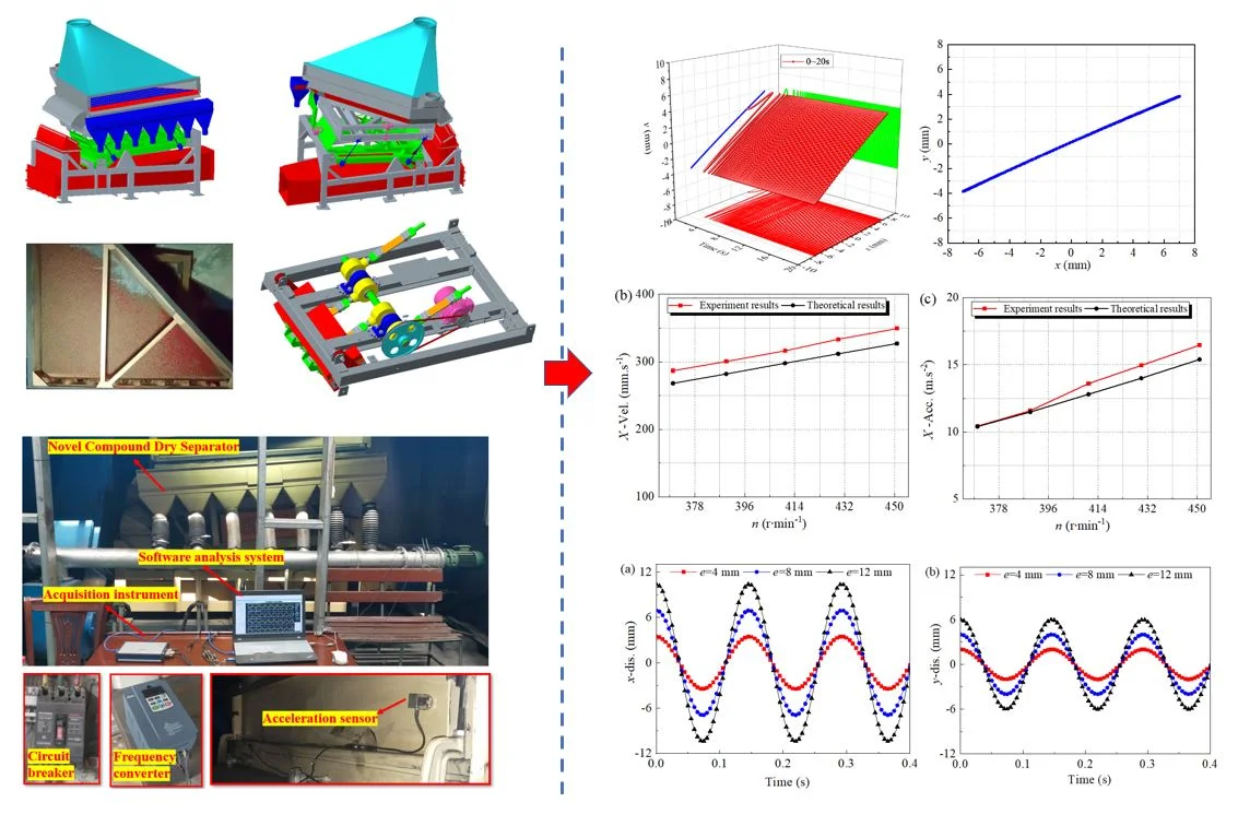
- The vibrations of the NCDS were examined by experimental test and compared with theoretical calculation.
- The effects of key parameters on dynamics of the NCDS were analyzed.
1. Introduction
Dry screening of viscous and fine-grained minerals plays an indispensable role in processing coal ore, and iron or gold deposited rocks, etc. [1-5]. However, conventional screening equipment (linear vibrating or circular vibrating screens) usually encounter many problems, such as low efficiency when processing moist materials [6-9]. Great advantages have been showed of flip-flow screen, including the enhancement of vibration strength, the function of automatic cleaning and the hard blockage of the mesh, etc. [10-12]. The flip-flow screen with elastic screen surface has been widely used for screening fine-grained minerals due to its good performance [13, 14]. To achieve the best screening performance of flip-flow screen with simultaneously increasing lifetime, a better understanding of its dynamics is necessary, thereby optimizing structural design [15].
Till date, many researchers investigated and analyzed the dynamic response and the operation mechanism of the flip-flow screen. Increasing the relative amplitude and avoiding undesirable resonances of the inner and outer screen boxes can be realized to improve the screening performance [16]. The dynamic response of the flip-flow screen largely affects its screening efficiency and processing capacity and the dynamic response curves were measured and analyzed under different operating conditions [17, 18]. To obtain a comprehensive understanding of the flip-flow screen machinery, three groups of parameters about design, technological, operation were optimized as a whole and the relationship between productivity, screen efficiency, energy consumption was optimized [19]. Kinematics of the screen boxes and the surface of the flip-flow screen were investigated using acceleration sensor and laser displacement sensor, the screening experiments results showed a high screening efficiency [20]. The vibration and dynamic characteristics and the screening performance of fine coal have been investigated, the results showed that the flip-flow screen can achieve an efficient sieving when dealing with fine moist coal [21-23].
Spring failure often occurs in the life cycle of screening equipments. Spring is an important factor to ensure the screening performance and safety of flip-flow screen. The adverse working conditions and violent alternating load may lead to the cracking of the guide spring, or result in the reduction of spring stiffness or even damage. Bearing stress analysis and correct selection have positive significance to improve the service life of bearing. Therefore, the development of high reliability and high efficiency of the screening equipment is imperative. In this paper, the dynamical characteristics of the flip-flow screen with crankshaft-link structure (FFSCLS) was systematically studied. The interaction forces of the inner and outer screen boxes with the crackshaft rotational speed, stiffness coefficient of the guide springs and rubber springs were carried out. At the same time, the service life of bearings was discussed.
2. Mathematical model
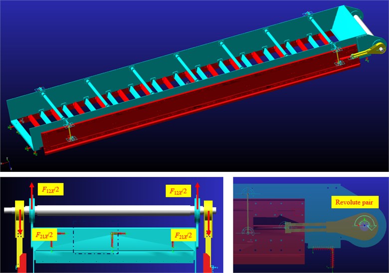
The complete model of the FFSCLS was constructed and shown in Fig. 1(a). Generally, the FFSCLS consists of inner and outer screen boxes, polyurethane screen panels, crankshaft, link, power system, rubber and guide springs. The length and width of the whole screen surface is 8.82×2.2 m, and the screen surface inclination angle is 20 degrees. The screen surface is composed of 28 independent polyurethane screen panels. The crankshaft rotation drives the inner and outer screen boxes staggered operation, and then drives the polyurethane screen panels to achieve relaxation and tension. Under the slackening and tensioning of the screen surface, the particles on the screen surface can achieve a high ejection acceleration of 30-50g. Under these high-intensity vibration conditions, particles are less likely to clog the screen holes, ensuring screening efficiency and capacity [24, 25].
Fig. 1Mechanical structure of the flip-flow screen with crankshaft-link structure (FFSCLS)
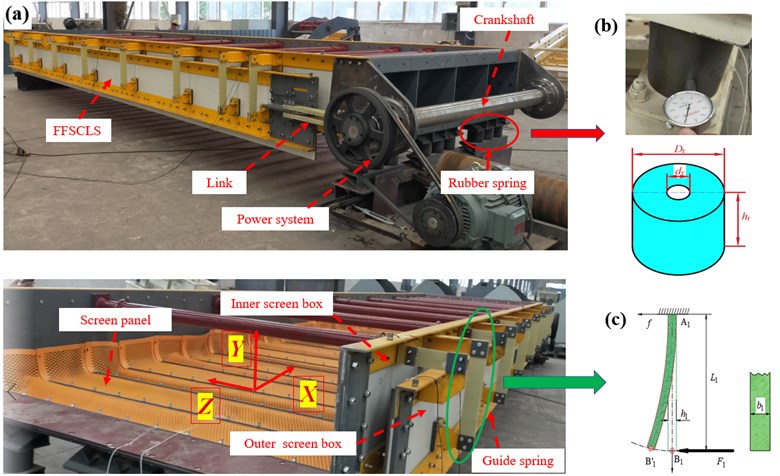
The rubber spring used in FFSCLS is shown in Fig. 1(b) Compared with metal springs, rubber springs have smaller noise, smaller amplitude fluctuations in the over-resonance region. Shore hardness of rubber spring can be measured by LX-A Shore hardness tester, and stiffness coefficient of rubber spring can be obtained by Eqs. (1)~(4):
where, is the shear elastic modulus of rubber spring, MPa; is the elastic modulus of rubber spring, MPa; is the shape coefficient of the circular rubber spring; is shore hardness of rubber spring; is the outer diameter of the rubber spring, mm; is the inner diameter of the rubber spring, mm; is the free height of rubber spring, mm; is the shear stiffness coefficient of rubber spring, N∙mm-1; is the axial stif fness coefficient of rubber spring, N∙mm-1.
The guide springs are made of Glass Fiber Reinforced Plastics (GFRP). GFRP has the characteristics of light weight, low elastic modulus and high fatigue strength. The spring stiffness of the guide spring is determined by the number of guide springs, material properties, section parameters and other factors. The equivalent mechanical model of the guide spring is shown in Fig. 1(c). is the fixed point between the guide spring and the inner screen box, is the fixed point between the guide spring and the outer screen box, and the length between and is . Under the action of force , point moves from its initial position to point , then the deflection of point can be obtained by Eq. (5) [26]:
where, is the elastic modulus of the guide spring, is the moment of inertia of the cross section of the guide spring, . The stiffness coefficient of the guide spring along the X direction can be calculated by Eq. (6):
where, is the number of guide springs, is the width of guide springs, is the thickness of guide springs.
Fig. 2Dynamical model of the FFSCLS
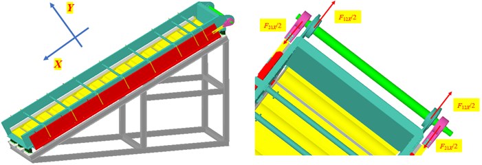
A corresponding dynamical model of the FFSCLS was established as shown in Fig. 2. The displacement of the outer screen box screen box and the displacement of the inner screen box , the velocity of the outer and inner screen box (, ), the acceleration of the outer and inner screen box (, ) can be written as Eq. (7-8) [27]:
where, and are the mass of the outer screen box and inner screen box, respectively; e and are the eccentricity and the rotational speed of the crankshaft, respectively; ()are the equivalent stiffness (damping) coefficients of the rubber springs, respectively. The damping coefficient of rubber spring has little influence on the vibration system, therefore can be ignored. Thus, Eqs. (7-8) can be simplified to Eqs. (9-10), respectively [28, 29]:
The component force of the interaction force between the outer screen box and the crankshaft in the -direction and the component force between the inner screen box and the crankshaft in the - direction can be expressed as:
Based on Eqs. (9-11), the interaction force (, ) can be written as:
Finally, Eq. (12) can be obtained:
3. Results and discussion
3.1. Dynamic analysis of the FFSCLS based on MATLAB/Simulink
The structural parameters of the FFSCLS are listed in Table 1. In order to further analyze the time domain dynamical characteristics of the FFSCLS, MATLAB/Simulink was used to establish a simulation model based on the dynamics model. Sine Wave module in Sources module library was used as excitation signal. Using this module, cosine signal was output, and sine signal was output when the phase increased /2. The Scope oscilloscope module in the receiver module library was used to output the displacement, velocity and acceleration signal curve, and the and simulation models of the inner and outer screen boxes are shown in Fig. 3.
Table 1Parameters of the FFSCLS
Parameters | Value | Parameters | Value |
, (kg) | 3500 | Motor Power, (kW) | 35 |
, kg | 5300 | Rated speed, (rpm) | 1460 |
, (mm) | 12 | , | 2.65 |
, (mm) | 160 | Rotational speed of the crackshaft, (rpm) | 550 |
, (mm) | 40 | , (GPa) | 42 |
, (mm) | 120 | , (mm) | 400 |
, (N∙mm-1) | 1670 | , (mm) | 80 |
, (N∙mm-1) | 6635 | , (mm) | 6 |
Damping ratio | 0.01 | , (N∙mm-1) | 240 |
According to Table 1, the corresponding sine and cosine excitation was applied respectively, the excitation angular frequency was 57.6 rad·s-1 which equal to 550 rpm, and the simulation time was set to 6 s. The time-domain response simulation results are shown in Fig. 4, and the Lissajous Figure of displacement in stable period is shown in Fig. 5.
Fig. 3Simulation model of the outer and inner screen boxes
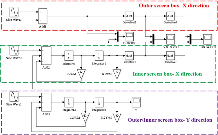
Fig. 4Time-responses of displacement about the FFSCLS by simulation
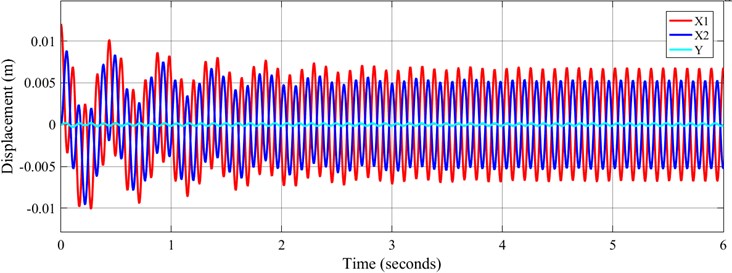
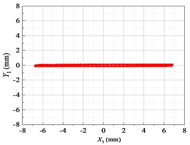
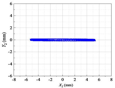
Fig. 5Lissajous displacement patterns of the FFSCLS by simulation
According to the simulation results in Fig. 4, when FFSCLS running at the set working frequency, 0-4 s is the disorder stage. During disorder stage, the displacement amplitude of the inner and outer screen box in the direction are relatively large. The maximum displacement amplitude of the outer screen box in the direction is 12.0 mm, and the maximum displacement amplitude of the inner screen box in the direction is 8.8 mm. After 4 s, the FFSCLS starts to run steadily. In stable operation stage, the displacement amplitude of the outer screen box is about 6.96 mm, and the displacement amplitude of the inner screen box is about 5.12 mm. In addition, the displacement curve can be found that the phase difference between the inner and outer screen boxs in the direction is 180°. The simulation results in direction show that the displacement of screen body in direction is very small, and the maximum displacement amplitude is less than 0.2 mm.
It can be seen from the Lissajous diagram of displacement in the stable period in Fig. 5 that the vibration track of the inner and outer screen boxes in the stable operation stage is a straight line along the direction. The trajectory shows that the inner and outer screen boxes are centered on the midpoint and vibrate regularly.
The time domain response simulation results about velocity and acceleration in -direction of the FFSCLS are shown in Fig. 6. The waveform of velocity and acceleration in direction reached a stable value in about 4 seconds. The waveform of velocity and acceleration in steady stage are standard sine waves. It can also be seen from Fig. 6 that the velocity amplitude of the outer screen is stable at 398.12 mm∙s-1 and that of the inner screen is stable at 291.6 mm∙s-1. The velocity of the inner screen and outer screen are always opposite, with the relative velocity amplitude of 689.72 mm∙s-1. The acceleration amplitude of the outer screen box is 23.04 m∙s-2, and the acceleration amplitude of the inner screen box is 16.78 m∙s-2. The velocity and acceleration curves of the inner and outer screen boxes in the direction are 180°. The MATLAB/Simulink simulation analysis results provide a solid theoretical basis for the development of the FFSCLS.
Fig. 6Time-responses of vel. & acc. about the FFSCLS by simulation
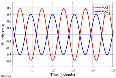
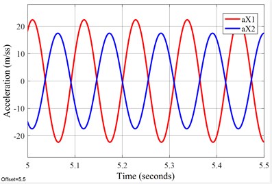
Table 2Comparisons of MATLAB/Simulink and experimental results of the FFSCLS
Parameters | Simulink results | Experimental results | Error (%) | |
Outer screen box | (mm) | 6.96 | 6.95 | –0.14 |
(mm∙s-1) | 398.12 | 371.40 | –6.71 | |
(m∙s-2) | 23.04 | 22.2 | –3.65 | |
Inner screen box | (mm) | 5.12 | 5.43 | 6.05 |
(mm∙s-1) | 291.6 | 291.05 | –0.19 | |
(m∙s-2) | 16.78 | 17.59 | 4.83 | |
The specific numerical comparison between experimental test results and MATLAB/Simulink results is shown in Table 2. The experiment was conducted in Ref. [27]. It can be seen from the Table 2 that the experimental results and MATLAB/Simulink results of the FFSCLS dynamical characteristics have a strong consistency. The relative error between experimental results and MATLAB/Simulink results is less than 6.71 %, which shows the capability of the mathematical model in investigating the vibration of the FFSCLS. Therefore, the dynamic characteristics of the FFSCLS can be accurately calculated before processing and manufacturing. That is also to say, the vibration characteristics of the FFSCLS can be controlled during the design stage to achieve the best screening performance.
3.2. Mechanical analysis of the FFSCLS based on multi-body dynamics
With the increase of production demand, the screening area, processing capacity and vibration quality of the flip-flow screen are also increasing. Due to the lack of a complete theory, guide springs cracking, bearings heating and other faults occur frequently. In this section, the mechanical analysis of the FFSCLS were carried out based on multi-body dynamics. The ADAMS software was selected to analyze the mechanical property of the flip-flow screen, such as interaction force (, ) between the outer screen box, inner screen box, and the crankshaft in the -direction. The ADAMS software consists of modeling, calculation, and postprocessing modules, which can be used to simulate the motion of the mechanical system, and to obtain the dynamics and dynamicals analysis at different times [21, 30, 31]. First, the three-dimensional model of the screen was simplified and established using the Creo Parametric software. Then, the entire model was converted into Parasolid format and imported into the ADAMS. Fig. 7 demonstrates the interface of the ADAMS software and parameters setting. The gravity acceleration was set as 9.81 m∙s-2. The material properties of the screen were selected to be steel and their corresponding densities were 7.80 × 10³ kg∙m-3. The constraint form between the crankshaft and the inner screen box is defined as revolute pair and a rotational velocity excitation was applied to the constraint. The rotational velocity function is given as follows: STEP (time, 0, 0, , ) + STEP (time, , 0, , –), where is the amplitude of rotational velocity excitation and , , represents start-up time, deceleration time, off time, respectively. In this study, the values of , , and were 5 s, 35 s, 40 s, and 57.6 rad·s-1 (550 rpm), respectively.
Fig. 7Interface of the ADAMS software and parameters setting
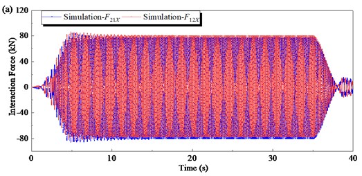
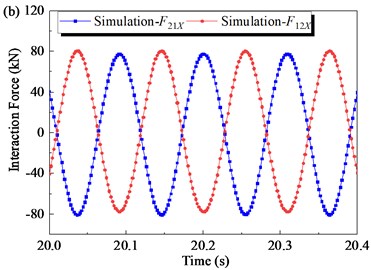
The mechanical property of the flip-flow screen was analyzed after the ADAMS simulation. Fig. 8 shows the time-domain curves of the interaction force along -direction obtained by simulation. At the starting stage (0 s-5 s), the rotational speed of the crankshaft gradually increases from 0 to 550 rpm. is a periodic load of variable amplitude, and the amplitude gradually increases with the increase of the rotational speed . When the crankshaft rotational speed is stable (5 s-35 s), the amplitude of basically remains unchanged. Then at the shutdown stage (35 s-40 s), the amplitude of gradually decreases to 0. The waveform trends of is similar to that of . It can be seen from the stable stage (5 s-35 s) that the phase difference between F12X and is 180°, and they are always equal in magnitude and opposite in direction. The resultant force of the inner and outer screen boxes in the direction is always equal to 0.
Fig. 8Time domain responses of interaction force obtained by simulation: a) under full-time; b) under steady working condition
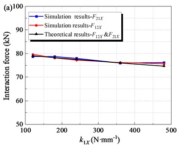
When other parameters remain constant, the alternating loads (, ) are related to the spring stiffness coefficients including the guide spring stiffness coefficient and the rubber spring stiffness coefficient . In order to study the influence of guide spring stiffness coefficient on mechanical properties of the FFSCLS, simulation experiments were carried out with of 120, 48180, 120, 240 and 360 N∙mm-1 respectively. Other parameters are shown in Table 1. The simulation and theoretical results of the amplitude of alternating loads (, ) under different guide spring stiffness conditions are shown in Fig. 9(a). As can be seen that, with the increase of guide spring stiffness, the amplitude of and gradually decreases. As increases from 120 to 240 N∙mm-1, the amplitude of decreases from 79 kN to 77.6 kN. As increases to 480 N∙mm-1, the amplitude of the alternating load continues to decrease to 74.7 kN. At the same time, the amplitude of downward trend is pretty much the same.
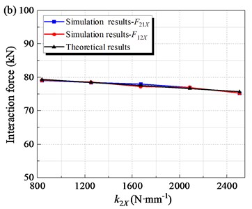
To research the effect of stiffness coefficient of the rubber springs on the mechanical property of the flip-flow screen, the of 835, 1250, 1670, 20 85 and 2505 N∙mm-1 were taken for discussion respectively. The amplitudes of interaction force (, ) under different are shown in Fig. 9b. The amplitudes of and decrease gradually with the increase of . The amplitude decreases from 79.3 kN to 77.6 kN when increases from 835 to 1670 N∙mm-1. Then, when further increases to 2505 N∙mm-1, the interaction force amplitude decreases to 75.7 kN.
The maximum relative error between simulation results and theoretical results is about 1.87 %. When the guide spring stiffness coefficient increases from 120 to 480 N∙mm-1, the amplitude of the alternating load is reduced by 5.4 %. When the spring stiffness coefficient increases from 835 to 2505 N∙mm-1, the amplitude of the alternating load decreases by 4.5 %. Therefore, appropriately increasing the spring stiffness and can help reduce the amplitude of alternating load. At the same time, increasing the stiffness will lead to an increase in the stress of the guide spring; Increasing the stiffness will increase the load transferred to the screen body support through the rubber spring, affecting the stability of the machine. Therefore, the spring stiffness and should be controlled within a reasonable range.
At present, the service life of the rubber spring and the guide spring used on the screen is about 2-3 years, which can satisfy the production demand. At the same time, the shape size of the rubber and guide springs can be changed properly, which can effectively reduce the maximum stress, and improve the service life of the spring and the whole screening machine.
Fig. 9The amplitude of interaction force along X- direction under the steady working condition: a) with different stiffness coefficient of the guild springs, k1X; b) with different stiffness coefficient of the rubber springs, k2X
3.3. Analysis of the FFSCLS bearing life
The driving part of the FFSCLS is equipped with aligning roller bearings, as shown in Fig. 10. Aligning roller bearings are subjected to the cyclic action of alternating loads during the screen operation. Therefore, bearing selection is particularly important to ensure its service life.
Bearing life can be expressed as [32]:
where, is the bearing life, hour; is life index, for Aligning roller bearing ; is the rotational speed of the crackshaft, rpm; is rated dynamic load, N; is equivalent dynamic load, N.
The equivalent dynamic load is calculated as follows:
where, is impact load factor and = 1.8-3.0; , denote the radial and axial dynamic loads borne by the bearing at the same time, N; , are radial dynamic load coefficient and axial dynamic load coefficient respectively.
The driving part of the FFSCLS consists of two pairs of bearings, one pair is aligning roller bearing 22226 which connect the crankshaft to the inner screen box, and the other pair is aligning roller bearing 22320 connecting the crankshaft to the outter screen box. From the above analysis, it can be seen that the two pairs of bearings bear alternating loads with equal magnitude and opposite directions. Load amplitude is related to crankshaft rotational speed and spring stiffness. When the spring stiffness is determined, the load amplitude is only related to the crankshaft rotational speed.
Fig. 10Roller bearings of the FFSCLS
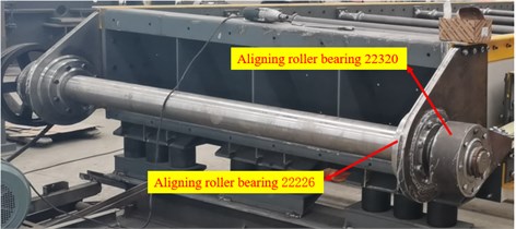
Table 3Parameters of the aligning roller bearing
Parameter | Value | Parameter | Value |
22226, (kN) | 630 | 22320, (kN) | 618 |
××, (mm) | 130×230×64 | ××, (mm) | 100×215×73 |
Impact load factor, | 3 | Radial dynamic load coefficient, | 1 |
Life index, | 10/3 | Axial dynamic load coefficient, | 0 |
Table 3 lists the bearing models and calculation parameters. The bearing only bears radial load and the axial load is very small. The radial dynamic load coefficient and axial dynamic load coefficient are 1 and 0 respectively. is radial rated dynamic load of bearing.
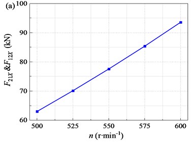
To research the effect of the rotational speed of the crankshaft on the mechanical property of the flip-flow screen, the rotational speed of 500, 525, 550, 575, and 600 rpm were taken for discussion respectively. The amplitudes of interaction force (, ) under different rotational speed are shown in Fig. 11(a). Generally, the amplitudes of and increase significantly with the increase of . The amplitude increases from 63.0kN to 77.6kN mm when n increases from 500 to 550 rpm. When further increases to 600 rpm, the amplitude of the force increases to 93.6 kN. With increases from 500 to 600 rpm, the amplitudes of interaction force increases by 48.6 %. Further increase of will increase the interaction force of the screen body rapidly. Too high speed brings too high force, which is bad for the service life of the whole machine, especially the life of the bearings.
Fig. 11Interaction force and bearing life with different rotational speeds n
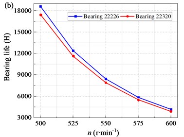
Bearing service life varies with crankshaft rotational speed as shown in Fig. 11(b). The rated dynamic load of the two pairs of bearings and the amplitude of alternating load are both the same. Therefore, the curve trend of bearing life varies with the speed is roughly the same. Taking bearing 22320 for example, the service life is about 17437.6 hours with the crankshaft rotational speed of 500 rpm. With the increase of crankshaft rotational speed, the service life of bearing continues to decrease, and the downward trend is clear. When the crankshaft rotational speed is 550, 600 rpm, the bearing service life is reduced to 5500.4 and 3883.2 hours respectively. Therefore, the crankshaft rotational speed should be controlled.
The correct selection of bearings has positive significance for improving the life of the bearing. As coal production enterprises become larger, there is an urgent need for the enlargement of the screening equipment. Larger screening equipment is bound to be accompanied by greater alternating load. Excessive alternating load may cause the bearing to be overheated in the short time, breaking the continuous of screening process and accelerating the damage of the bearings. Therefore, it is especially important for bearing force analysis and life calculation.
4. Conclusions
1) The vibration characteristics of the flip-flow screen with crank-link structure (FFSCLS) were studied through MATLAB/Simulink method. The dynamic characteristics and vibration behavior of inner and outer screen boxes were obtained. The waveforms of displacement, velocity and acceleration of inner and outer screen boxes in steady stage are standard sine waves. The trajectories of the outer and inner screen boxes approximates straight line. The results of experimental and MATLAB/Simulink have strong consistency with the maximum deviation of within 6.71 %. The vibration characteristics of the FFSCLS can be described perfectly with the dynamic model.
2) The MBD simulation results indicated that the interaction forces of the inner and outer screen boxes are equal in magnitude and opposite in direction, the resultant force is always equal to 0. The amplitudes of the interaction forces increase with the increase of crackshaft rotational speed and decrease with the increase of stiffness coefficient of the guide spring and rubber springs. Appropriate increase of spring stiffness is helpful to reduce the amplitude of alternating load. The crackshaft rotational speed and spring stiffness should be controlled to reduce the interaction forces.
3) The bearing life was studied. With the increase of crankshaft speed, the bearing life continues to decrease. High crankshaft speed is not conducive to the service life of the whole machine, especially the service life of bearings. The force analysis and correct selection are the guarantee of the bearing service life. The analysis method can provide a feasibility for the enlargement of the FFSCLS and provide a certain reference for the promotion of this kind of screening equipment.
References
-
L. Peng et al., “A review on the advanced design techniques and methods of vibrating screen for coal preparation,” Powder Technology, Vol. 347, pp. 136–147, Apr. 2019, https://doi.org/10.1016/j.powtec.2019.02.047
-
H. L. Dong, C. S. Liu, Y. M. Zhao, and L. L. Zhao, “Review of the development of dry coal preparation theory and equipment,” Advanced Materials Research, Vol. 619, pp. 239–243, Dec. 2012, https://doi.org/10.4028/www.scientific.net/amr.619.239
-
V. P. Barbosa, A. L. Menezes, R. Gedraite, and C. H. Ataíde, “Vibration screening: A detailed study using image analysis techniques to characterize the bed behavior in solid-liquid separation,” Minerals Engineering, Vol. 154, p. 106383, Aug. 2020, https://doi.org/10.1016/j.mineng.2020.106383
-
P. W. Cleary, M. D. Sinnott, and R. D. Morrison, “Separation performance of double deck banana screens – Part 1: Flow and separation for different accelerations,” Minerals Engineering, Vol. 22, No. 14, pp. 1218–1229, Nov. 2009, https://doi.org/10.1016/j.mineng.2009.07.002
-
P. W. Cleary, M. D. Sinnott, and R. D. Morrison, “Separation performance of double deck banana screens – Part 2: Quantitative predictions,” Minerals Engineering, Vol. 22, No. 14, pp. 1230–1244, Nov. 2009, https://doi.org/10.1016/j.mineng.2009.07.001
-
Keshun Liu, “Some factors affecting sieving performance and efficiency,” Powder Technology, Vol. 193, No. 2, pp. 208–213, 2009.
-
A. Noble and G. H. Luttrell, “A review of state-of-the-art processing operations in coal preparation,” International Journal of Mining Science and Technology, Vol. 25, No. 4, pp. 511–521, Jul. 2015, https://doi.org/10.1016/j.ijmst.2015.05.001
-
O. A. Makinde, B. I. Ramatsetse, and K. Mpofu, “Review of vibrating screen development trends: Linking the past and the future in mining machinery industries,” International Journal of Mineral Processing, Vol. 145, pp. 17–22, Dec. 2015, https://doi.org/10.1016/j.minpro.2015.11.001
-
Z. Gangfeng, Z. Jinbo, X. Wandong, and L. Shili, “Banana flip-flow screen benefits coal preparation,” Filtration + Separation, Vol. 53, No. 4, pp. 38–41, Jul. 2016, https://doi.org/10.1016/s0015-1882(16)30170-7
-
G. Qingliang and G. Gu, “Application of flip flow screen in sihe coal preparation plant,” in XVIII International Coal Preparation Congress, pp. 913–918, 2016, https://doi.org/10.1007/978-3-319-40943-6_142
-
D. P. Mishra and S. K. Das, “Application of polymeric flocculant for enhancing settling of the pond ash particles and water drainage from hydraulically stowed pond ash,” International Journal of Mining Science and Technology, Vol. 23, No. 1, pp. 21–26, Jan. 2013, https://doi.org/10.1016/j.ijmst.2013.01.004
-
H. Akbari, L. Ackah, and M. Mohanty, “Performance optimization of a new air table and flip-flow screen for fine particle dry separation,” International Journal of Coal Preparation and Utilization, Vol. 40, No. 9, pp. 581–603, Sep. 2020, https://doi.org/10.1080/19392699.2017.1389727
-
E. Zhou, G. Yan, X. Weng, Z. Zhang, P. Zhao, and B. Zhang, “A novel and low cost coal separation process: Combination of deep screening classification and gravity separation,” Powder Technology, Vol. 367, pp. 568–575, May 2020, https://doi.org/10.1016/j.powtec.2020.03.054
-
B. Wu, X. Zhang, L. Niu, X. Xiong, Z. Dong, and J. Tang, “Research on sieving performance of flip-flow screen using two-way particles-screen panels coupling strategy,” IEEE Access, Vol. 7, pp. 124461–124473, 2019, https://doi.org/10.1109/access.2019.2938847
-
Y. Zhao, C. Liu, M. Fan, and L. Wei, “Research on acceleration of elastic flip-flow screen surface,” International Journal of Mineral Processing, Vol. 59, No. 4, pp. 267–274, Jul. 2000, https://doi.org/10.1016/s0301-7516(99)00079-4
-
S. Gong, X. Wang, and S. Oberst, “Non-linear analysis of vibrating flip-flow screens,” in MATEC Web of Conferences, Vol. 221, p. 04007, 2018, https://doi.org/10.1051/matecconf/201822104007
-
C. Yu et al., “Stability analysis of the screening process of a vibrating flip-flow screen,” Minerals Engineering, Vol. 163, p. 106794, Mar. 2021, https://doi.org/10.1016/j.mineng.2021.106794
-
C. Yu, X. Wang, K. Pang, G. Zhao, and W. Sun, “Dynamic characteristics of a vibrating flip-flow screen and analysis for screening 3 mm Iron Ore,” Shock and Vibration, Vol. 2020, pp. 1–12, May 2020, https://doi.org/10.1155/2020/1031659
-
H. Zhai, “Integral optimization of systematic parameters of flip-flow screens,” Journal of China University of Mining and Technology, Vol. 29, No. 1, pp. 78–82, 2004.
-
Z. Chen et al., “Application of screening using a flip-flow screen and shallow groove dense-medium separation in a steam coal preparation plant,” International Journal of Coal Preparation and Utilization, Vol. 42, No. 8, pp. 2438–2451, Aug. 2022, https://doi.org/10.1080/19392699.2020.1855581
-
H. Jiang et al., “Kinematics characteristics of the vibrating screen with rigid-flexible screen rod and the behavior of moist coal particles during the dry deep screening process,” Powder Technology, Vol. 319, pp. 92–101, Sep. 2017, https://doi.org/10.1016/j.powtec.2017.06.036
-
M. Jahani, A. Farzanegan, and M. Noaparast, “Investigation of screening performance of banana screens using LIGGGHTS DEM solver,” Powder Technology, Vol. 283, pp. 32–47, Oct. 2015, https://doi.org/10.1016/j.powtec.2015.05.016
-
F. S. Guerreiro, R. Gedraite, and C. H. Ataíde, “Residual moisture content and separation efficiency optimization in pilot-scale vibrating screen,” Powder Technology, Vol. 287, pp. 301–307, Jan. 2016, https://doi.org/10.1016/j.powtec.2015.10.016
-
B. Zhang, G. Zhu, B. Lv, and G. Yan, “A novel and effective method for coal slime reduction of thermal coal processing,” Journal of Cleaner Production, Vol. 198, pp. 19–23, Oct. 2018, https://doi.org/10.1016/j.jclepro.2018.06.306
-
S. Gong, S. Oberst, and X. Wang, “An experimentally validated rubber shear spring model for vibrating flip-flow screens,” Mechanical Systems and Signal Processing, Vol. 139, p. 106619, May 2020, https://doi.org/10.1016/j.ymssp.2020.106619
-
Xiaojun. Wang, “Research on the fracture problem of leaf spring,” (in Chinese), Automobile Applied Technology, Vol. 24, pp. 109–110, 2018.
-
H. Li, C. Liu, E. Zhou, and L. Shen, “Research on dynamic and vibration behaviors of a flip-flow screen with crankshaft-link structure,” Journal of Vibroengineering, Vol. 24, No. 5, pp. 836–847, Aug. 2022, https://doi.org/10.21595/jve.2022.22455
-
H. Li, C. Liu, L. Shen, L. Zhao, and S. Li, “Kinematics characteristics of the flip-flow screen with a crankshaft-link structure and screening analysis for moist coal,” Powder Technology, Vol. 394, pp. 326–335, Dec. 2021, https://doi.org/10.1016/j.powtec.2021.08.042
-
H. Li, C. Liu, L. Shen, and L. Zhao, “Vibration characteristics of an industrial-scale flip-flow screen with crank-link structure and parameters optimization,” Shock and Vibration, Vol. 2021, pp. 1–16, Sep. 2021, https://doi.org/10.1155/2021/2612634
-
H. Jiang et al., “Simultaneous multiple parameter optimization of variable-amplitude equal-thickness elastic screening of moist coal,” Powder Technology, Vol. 346, pp. 217–227, Mar. 2019, https://doi.org/10.1016/j.powtec.2019.01.052
-
Z. Zhou et al., “Kinematics of elastic screen surface and elimination mechanism of plugging during dry deep screening of moist coal,” Powder Technology, Vol. 346, pp. 452–461, Mar. 2019, https://doi.org/10.1016/j.powtec.2019.02.023
-
Z. M. Wu et al., “Simulation research on service life of the driving gear bearing of the main reducer,” (in Chinese), Technology and Market, Vol. 29, pp. 7–10, 2022.
About this article

This work is financially supported by the National Natural Science Foundation of China (51904298), the Doctoral Scientific Research Foundation of Suzhou University (2020BS004).
