Abstract
FxLMS algorithm has been widely used in active vibration control field theoretically. This paper is aimed at the complex situations in actual environment including interference and occasional divergence due to algorithm. Firstly the effects to control process and result caused by those situations are analyzed, then select different means based on different characteristics of the effects to deal with them, and integrate all those means to derive a new optimal control strategy which is suitable to actual applications. The experiment shows that the improved control strategy can response effectively different occasional situations without any weakness of normal control, and it can promote the practical application ability of the algorithm and is able to adapt to complex environments in active vibration control.
1. Introduction
In recent years, with the increasing demand for vibration control, the frequency band need to control is becoming wider and wider. The emergence of active vibration control, also known as ANC greatly promotes the development of vibration control [1], and the minimum mean square error (LMS) algorithm is widely used in the field of active control. Because of the physical distance between the secondary source and the error sensor, the LMS (FxLMS) is utilized as the LMS algorithm in the field of mechanical vibration control, and has achieved good control results in the laboratory environment [2]. However, due to the actual application environment is not possible to maintain isolation from the outside environment, the situation such as the mechanical operation interference, human disturbance and system characteristics of vibration equipment change are inevitable, these changes in the external environment can be divided into three categories: 1) The vibration signal of the device changes due to the additional mechanical equipment turn on or turn off; 2) Intermittent impulse, such as the movement of the surrounding personnel, goods, etc.; 3) The characteristics of the system are changed, and so on.
These unpredictable environmental factors can lead to the deterioration of active control and even divergence, resulting in serious consequences. For these reasons, it is necessary to do some research on the control strategy of active control in a complex environment. This paper is based on the application of FxLMS algorithm in the actual usage, and propose an optimizing control strategy without changing the core algorithm. The purpose is to enhance the adaptive algorithm in the active control of the application ability.
2. The basic principle of FxLMS algorithm
The basic block diagram of FxLMS algorithm is showed in Fig. 1. is the primary path, represents the primary source to the error sensor transfer function; for the controller; and are real secondary path and the estimated secondary path; , , , respectively for a single band reference signal, filtering-reference signal, the desired signal, the control signal. is the error signal, the goal of our control:
The objective function is , then:
According to the steepest descent principle, the gradient of the objective function is:
Assume that it is zero, then get optimal weight coefficient as follows:
In the practical application, the error square of a single sample is generally used to approximate the objective function, so:
3. The influence of complex environment on FxLMS algorithm
3.1. The influence of the characteristics of vibration signal on the algorithm
This article is about active vibration control of machinery device, and the advantage of using narrow-band algorithm is that it can reduce the amount of computation and improve the convergence speed. However, the disadvantage is due to the limitation of the computation quantity, so we cannot carry out the full band control. So there must be a frequency-choosing course before the core algorithm is implemented [3, 4]. From Fig. 1 it can be seen that the collected signal is first narrow-band filtered before entering the algorithm, so when the characteristics of vibration signal change, and the algorithm cannot be adjusted in time, it will lead to false control, leakage control, which lose the meaning of active control [5].
3.2. The influence of external interference on the algorithm
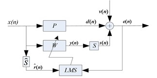
If there is an external interference in the operation of the algorithm, the Fig. 1 will be changed as Fig. 2.
Then the error signal in the Eq. (1) becomes :
In the same way, the optimal weight coefficient is obtained:
and Eq. (6) would becomes:
Among them, is the filter coefficients in the absence of noise. It can be seen that the existence of noise will inevitably affect the convergence process of filtering. Also, if the external disturbance is white noise, the algorithm can generate the oscillation in the convergence process and increase the misadjustment when converge to steady state, but the optimal value of the adaptive filter does not change, which shows that it does not affect the final control effect. While if the interference is a short time impulse, then the algorithm will converge to a wrong direction. On the other hand, the impulse can change the filter weight and increase the output of the controller, which not only needs higher requirements to the system hardware equipment, but also is not conducive to the stability of the system. When this situation appears, the algorithm will need a little more time to go back to the original position which is not what we expected.
Fig. 1Basic block diagram of FxLMS algorithm for continuous system
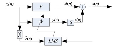
Fig. 2Basic block diagram of FxLMS algorithm with external interference
3.3. Influence of convergence factor on Algorithm and control
For FxLMS algorithm, the value of convergence factor u directly affects the algorithm’s execution. In paper [6], the author has derived the sufficient conditions for the convergence of LMS algorithm (the premise of the following formula is that the actual secondary path and secondary path estimation are same):
Therefore, the upper bound of u is determined by the total input power of . There is no problem in the mathematical derivation. However, it is not feasible to maintain constant power in operation. And the maximum value of can be quite different because of the variation of the vibration caused by the fault. In the literature [7], the authors analyze the convergence of FxLMS algorithm, and show that the weight coefficients is updated to the optimal weight coefficient in the convergence process as showed in Fig. 3. From the figure, would gradually go far from the optimal value when is not satisfied with the Eq. (10).
4. The improved control strategy
Different interference on the control algorithm has different effects. The characteristics of the interference are analyzed below.
For the vibration signal characteristics change, such as machines on isolation device are turned on or off, the speed changes of the rotating machines and so on. The improved control strategies need to finish frequency band selection with intelligence in front of the control, and re-selected frequency according to changes in signal characteristics in the control process. The main feature is that the extra spectrum signal appears or the current controlled signal lost in the acquisition of the original signal.
For impulse interference, such as when there are big-ticket items or items hit the floor, it will generate such interference. When the impulse comes, although the signal detected by error sensor increases instantaneously, but because the interference is momentary and it will be completely attenuated soon, so the ideal control strategy is to “ignore” its effect, not response on it, and maintain normal convergence process. According to the previous analysis, the general LMS algorithm would make the controller weight coefficients tremendous change when such interference added on it, and the corresponding controller output will increase a lot. Although the CFxLMS algorithm of the constraint weight function in [8] has some constraints on weight coefficients, to ensure the change will not be too dramatic. The negative influence is reduced to some extent, but the constraints affect whenever the interference exists. So it will perform poor when there is no interference. When the impulse comes, the energy of the whole frequency band in frequency domain increases, so the diverse frequency bands , which is different from other interference and depended on the actual application, can be used to identify the impulse interference (In the following experiment, is 4). The proper means to process the interference can be realized by adding a Boolean factor in Eq. (9) in which the factor when there is impulse interference and when there is no impulse interference:
Fig. 3The geometric meaning of convergence process in FxLMS
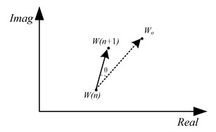
Fig. 4Variation of filter coefficients with iteration
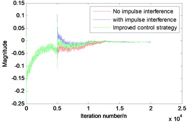
Fig. 4 is the result of computer simulation to the impulse, the variation of filter weight coefficients with iteration for the original algorithm and the improved algorithm using Eq. (11) is showed. It can be observed that the coefficient of the controller is instantly deviated from the normal value, and both the algorithm will converge back slowly. But the improved algorithm reduces the impact of the impulse, and can reach the optimal value more quickly than original algorithm.
For the divergence caused by the algorithm itself in the complex environment, the characteristics of the algorithm divergence are that it only appears in the control band, while other bands will not be affected. The algorithm can converge normally in laboratory conditions, but it cannot be used in practical applications. There are two reasons that can lead this phenomenon. One is the convergence factor of the algorithm. The other is the fact that the secondary channel characteristics of the vibration isolation device change too much which make the current convergence factor cannot meet the Eq. (10). In the practical application, it is difficult to get the secondary path function in real time, so the convergence of the algorithm can be improved by reducing the convergence factor .
The difficulty in dealing with the above three kinds of situations is that the identification of the interference type, once the cause of the abnormal control, can be adjusted according to the above method. Based on the above analysis, the improved control strategy is described as follows: 1) The collected original signal FFT transform, calculating the amplitude spectrum; 2) According to the obtain spectrum, selecting strongest frequency bands to control, is the maximum frequency band number the algorithm can achieve; 3) Save the spectrum data before the control, then the algorithm enters the control step; 4) According to the data before the control, the vibration characteristics of the original data are compared every time. According to the characteristics of the above analysis, determine the cause of abnormal before we take the corresponding measures.
The flow chart is given in Fig. 5.
5. Experiment and analysis
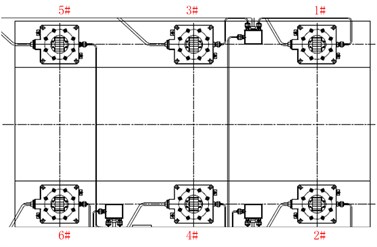
In order to verify the validity of this method, the corresponding experimental verification is done in this part. Take the narrow band FxLMS algorithm, the controller is the DSP TMS6678 chip, the sampling frequency is 1000 Hz, the vibration signal the vibration isolation device is generated by vibration exciter. Six inertial actuators are placed in the lower layer symmetrically. The controller output is connected to a power amplifier in order to drive the inertial actuator. The arrangement of the six inertial actuators is presented in Fig. 6.
Fig. 5The flow chart of control strategy
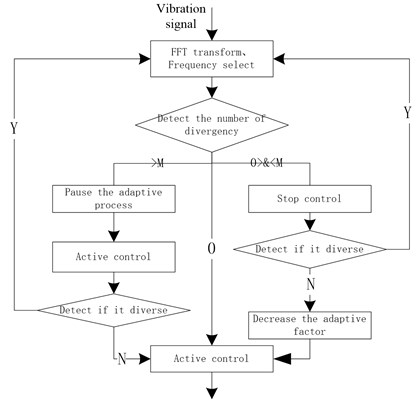
Fig. 6Actuator arrangement diagram
In the running process of the algorithm, the force hammer is used to simulate the external shock, and changing the excitation frequency to simulate external persistent disturbances or the vibration signal changes, and increasing convergence factor to simulate the algorithm divergence. Record the vibration signal in the error measuring points when the interference comes.
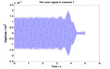
Fig. 7 shows that when the algorithm converges to a stable state, each error signal at measuring point 1 using the unimproved control strategy (Fig. 7(a), directly executing FxLMS algorithm) and the improved control strategy (Fig. 7(b)) when the impulse interference arrives. It can be seen that the impact of the shock is inevitable, but the recovery ability between different strategies is different. From Fig. 7(a) impulse comes at 33.58 s moment. After 2.60 s (36.18-33.58), the algorithm to return to the state of no interference, but in Fig. 7(b) it only needs 0.84 s (13.14-12.30) to achieve the same state. The reason is that the influence to the latter controller is less than that to the former one due to the improved control strategy, and the filter weight coefficients just deviate a little from the optimal coefficient of control. So the starting point which the adaptive converge from is better than the former.
Fig. 8 describes a situation when a sudden change appears in the controlled vibration signals in the control process (here refers to frequency). The controller is able to quickly track the new signal and continuous control. The figure is about the same control process but deal by different narrow-band filter, among them, the red line represents 80 Hz signal, the blue one is for 90 Hz signal. It can be seen that signal changes from 80 Hz to 90 Hz at about 35 s and both of them can be controlled effectively and quickly.
Fig. 9 shows that when a frequency band under control appears to diverge in the control process, the control strategy can detect the divergence and halve the convergence factor, so the algorithm can re-control effectively.
Fig. 7Vibration of the error measuring point after the impulse interference
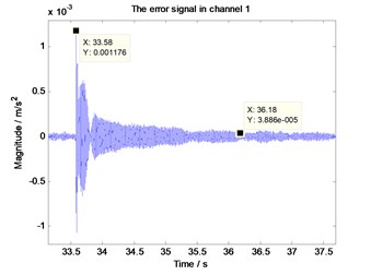
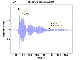
Fig. 8The error signal when the source vibration signal frequency change
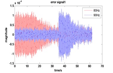
Fig. 9The error signal when the algorithm divergence under the improved strategy
6. Conclusions
The FxLMS algorithm has been widely used in the research of active vibration isolation, but there are few applications in the real environment. The reason is that most of the researchers focus on studying the mechanism, the algorithm, and lack of understanding of the field factors, without taking the practical application environment into account. The purpose of this paper is to solve the practical problems, which is also an indispensable step for the active control going into the application. The proposed control strategy can also be used in other control algorithm. Theoretical analysis and experimental results show that the control strategy proposed in this paper can effectively deal with the complex external environment factors, greatly improving the application level of active vibration isolation.
References
-
Fuller C. D., Elliott S. J., Nelson P. A. Active Control of Vibration. Academic Press, London, 1997.
-
He Lin, Li Yan, Yang Jun. Theory and experiment of passive-active hybrid vibration isolation mounts using electromagnetic actuator and air spring. ACTA, Vol. 38, Issue 2, 2013, p. 241-249.
-
Shao T., Zheng Y. R. A variable step-size normalized sign algorithm for acoustic echo cancellation. IEEE International Conference Acoustics, Speech, Signal Processing. Dallas, TX, 2010, p. 333-336.
-
Wang Junfang, Li Zhenwei, Zhang Zhiyi Experimental study on adaptive isolation of periodical vibration. China Mechanical Engineering, Vol. 21, Issue 8, 2010, p. 978-982.
-
Zhang Jinguang, Hu Yefa, Song Chunsheng Research on active isolation feedforward control for magnetic suspension floating raft based on notch filter. China Mechanical Engineering, Vol. 24, Issue 17, 2013, p. 2341-2345.
-
Chen Ke’an Active Noise Control. National Defense Industry Press, Bei Jing, 2003, p. 67-81.
-
Dayong Zhou V. D. a new active noise control algorithm that requires no secondary path identification based on the SPR property. IEEE Transaction on Signal Processing, Vol. 55, Issue 5, 2005, p. 1719-1729.
-
Zhang Xuhui, Fu Yongling, Liu Yongguang Investigation in active vibration isolation based on a weight-constrained FxLMS algorithm. Noise and Vibration Control, Issue 2, 2008, p. 4-6.
About this article

