Abstract
A novel analytical model of vibration source for metro train based on “coupled vehicle and track basic unit” is established in this paper. The dynamic vehicle-track equations are completed with the displacement compatibility and the force equilibrium, and the model takes into account the infinite track structure, whole vehicle, track irregularity and wheel-rail Hertz contact. The special feature of track structure model is the periodical system of discrete supported sleepers, which converts the infinite integral equation into the combination in the wave number-frequency domain and simplifies the calculation progress. The rail dynamic responses and the wheel-rail contact force can be calculated easily. A complete software package TMCVT is programmed. A calculated example is achieved using the program. Compared the theoretical calculated results and the field tested results ,the coincidence with each other proved the analytical dynamic model for metro train coupled with vehicle and track is correct.
1. Introduction
Urban rail transit systems in 22 cities of China are rapidly developing now. The total length in operation within these cities is over 3173 km in the end of 2014. With the increasing denseness of metros, the vibrations generated by trains have become a hot environmental topic in a world, which will cause distress to sensitive machineries, adjacent structures, and annoyance to residents. Therefore, it is very necessary to study the dynamic responses propagation discipline to attenuate the adverse influence. And the key point is to establish an effective vehicle-track dynamic load analytical model to simulate the vibration source.
In the beginning of 1970s, wheel-rail dynamic interaction model was firstly established by Lyon [1] and Jenkins [2], which used to analysis the effect of some basic parameters, such as unsprung mass and rail stiffness. In 1982, the dynamic interaction with a moving train on the corrugation rail was taken into account, and the simulation was supposed to be similar to the reality [3]. In recent years, the research on vehicle-track interaction had also been carried out by Cai [4], the wheel-rail interaction was studied by the established model, in which “Bogie-Track “distributed parameter model was employed and the track was simulated as double-elastic discrete supported continuous beam. And analytical research of the wheel-rail dynamic interaction on high-speed track, heavy track and speed-up track were carried out by Zhai [5] with detailed models, in which considering the vertical and horizontal vehicle-track interaction.
According to the research work before, the vibration source is made up of the running train and the track structure. In this paper, a novel dynamic analytical model is established based on “coupled vehicle and track basic cell”, which takes into account whole-vehicle model, infinite track structure, track irregularity and wheel-rail Hertz contact. The model is deduced in the wave number-frequency domain, which provided great convenience for analyzing high-frequency dynamic interaction of the vehicle and track. The vibration analysis program TMCVT (Theoretical Model of Coupled Vehicle and Track) is achieved with MATLAB, and a calculation example is given.
2. Analytical model of coupled vehicle and track
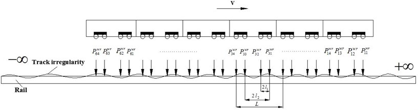
Fig. 1 shows the dynamics model coupled with whole vehicle and infinite track. The vibration induced by train running on the track can be decomposed into the coupling vibration of wheel-axle dynamic load and track structure. The problem can be described with a basic mechanical model, a time-varying amplitude load of coupled vehicle-wheel system moving on the infinite track at the speed . As the time is infinite, the above time-domain equation can be transformed into the frequency domain solution by means of the Fourier Transform, the load position along the track in the space domain can also be converted to wave number space equation. With this two transformations, the train moving on the infinite track can be converted to the wave number-frequency domain, that is, the coupled integral equations in the time and space domain are mapped into an domain independent of time and space to be solved, and a complex space-time integral equation is transformed into the simple combination in the wave number-frequency domain. Through the inverse transform, the results in the space-time domain can be obtained finally.
Fig. 1Dynamics model coupled with whole vehicle and infinite track
The dynamic equations and the solving process are all in the wave number-frequency domain, the displacement influence matrices of the track system and the vehicle system are all obtained based on the “coupled vehicle and track basic cell”. The wheel-rail contact forces are obtained in the basic cell. The dynamic responses of the vehicle and track structure in the coupling system could be solved, with the wheel-rail contact force added to the infinitely long track system. The obtained dynamic response of the entire system in the frequency domain can be transformed into the time frequency by the Inverse Fourier Transformation, which re-simplified the differential equation and also facilitate the dual-domain analysis.
2.1. Vehicle system dynamic equations
The vehicle can be considered as a multi-rigid-body system moving in the vertical longitudinal plane. The number of the freedom for the Vehicle model with secondary suspension system is 10 (take four-axis vehicles for example). The system equation can be obtained by the application of D’Alembert principle in each of the various rigid.
According to the Lagrange motion equations, dynamic equation transformations for the th carriage in frequency domain are as follows:
where , and are the mass, stiffness and damping matrices, , is the equivalent load and displacement vectors in frequency domain.
The wheel displacement of the whole vehicle with carriages can be defined as:
where:
is defined as the displacement vectors, displacement influence matrix and equivalent load vector of whole vehicle in frequency domain.
2.2. Track system dynamic equations
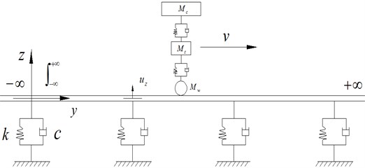
The rail is considered to be an infinite double-layer Timoshenko Beam. In case of the periodic track structure, the general response in the frequency domain is simplified in a form of summation within the track sleeper period instead of integral, which is obtained by transferring the moving loads on the rail to the moving of receiver backward within periodic sleeper distance . The advantage of this method is that all the dynamic analysis of the track system is carded out within sleeper distance . In this way, the track response to moving train can be obtained by a very simple calculation program, see Fig. 2.
Fig. 2Infinite track subjected to running train and coupled vehicle-track basic unit
With the load moving on the track structure at the speed v, the load location is , the vibration responses of any point can be solved by Duhamel integration, and the solution can be easily decomposed into the simplified form. The periodic analytical solution for the receiver point on the track, with the moving load on the track in frequency domain, can be expressed as:
where is the transfer functions, which has been settled in previous papers [6].
2.3. The displacement influence matrix of track
Green Function is also called point-source function or influence function [7], the distribution of field generated by the source at an arbitrary point can be derived through the Green function. In terms of train formation, all the train wheels are regularly arranged based on vehicle parameters.
For this problem, the displacement influence function between the wheels is defined to distinguish it from the traditional Green function. The displacement influence function indicates the rail displacement at caused by the unit load at , which is equivalent to the rail displacement at caused by the unit load at the origin, that is the displacement influence coefficient between the wheel loads:
Displacements of each wheel-rail contact point fulfill in frequency domain the following equation:
where is the column vector of the rail displacement, and:
is the rail displacement influence matrix of whole vehicle, where:
is displacement influence matrix composed of the rail displacement influence function between the wheels, which is the rail displacement of the th carriage generated by the unit loads of the nth carriage.
2.4. Track irregularity and wheel-rail Hertz contact
Track irregularity sample function is assampted as composing of many harmonic components of different frequencies, which is a definite function corresponding to a single space-angle frequency. The track irregularity vector in the frequency domain is as follows:
where is the vibration irregularity of frequency , is the track irregularity amplitude corresponding to the spatial frequency .
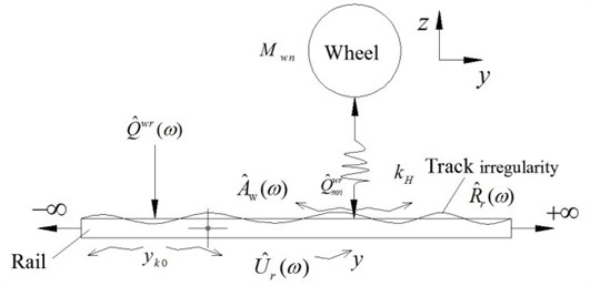
The elastic interaction between wheel and rail is based on general use of Hertz theory. In order to facilitate the solution in the frequency domain, the wheel-rail contact spring is simplified to a linear spring. Fig. 3 shows the Hertz contact of wheel and rail which the assumption of wheel-rail contaction is all the time.
Wheel-rail Hertz contact equation of the wheels can be simplified in frequency domain as:
where is Hertz contact stiffness, , , have been solved in Eqs. (2), (4), (5).
Fig. 3Hertz contact of wheel and rail
2.5. Dynamic equations of vehicle-track coupled system
Above all, the track is supposed to be infinite Timoshenko beam system with multi-layer discrete supports, and the vehicle is supposed to be two-spring system vehicle systems containing 10 degrees-of-freedom. Take Eqs. (2), (4), (5) into Eq. (6), the equation of dynamic equations of vehicle-track coupled system has been deduced as follows:
where is the unit matrix, and the other parameters have been explained before.
The wheel-rail contact force solved in Eq. (7) is substituted into the dynamic analytical expression Eq. (3) of the infinite track system, thus the analytical solution of the response of any point on the rails can be given under the loads of the whole vehicle.
3. Calculation examples
Based on the theory of the analytical vehicle-track coupled system, the vibration analysis program TMCVT is achieved with MATLAB. Using the program, the calculation example of dynamic response of rail acceleration with DTVI2 fastener in time domain is given in this paper. The results are calculated under the train speed of 60 km/h, as shown in Fig. 4(a). And Fig. 4(b) is the in-situ tested results of Beijing metro Line 5. Compared with the two data, theoretical caculated results coincide with the in-situ tested results, therefore, the calculation program is proved to be correct.
Fig. 4Therotical caculated and in-situ tested results
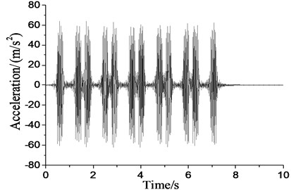
a)
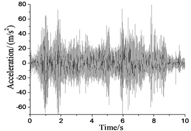
b)
The parameters of metro train vehicles are as follows: body mass 35 t, body mass moment of inertia 1700 tm2, bogie mass 4.6 t, bogie mass moment of inertia 9.62 tm2, vehicle length 19 m, axis distance 19 m, bogie spring coefficient 2 080 kN/m, bogie damping 240 kN·s/m, wheel spring coefficient 2 450 kN/m, wheel damping coefficient 240 kN·s/m, fixed distance 12.6 m, wheel mass 1.42 t.
The parameters of the track system are as follows: rail mass of unit length 60 kg/m; elastic modulus 2.10×10¹¹ Pa; cross-sectional area 7.60×10⁻³ m2; sectional moment of inertia 3.04 ×10⁻⁵ m4; damping ratio 0.01. The sleeper mass of unit length 50 kg; spacing 0.60 m. Track bed: mass 260 kg (combined mass of sleeper and track bed). DTVI2 fastener is used: spring/damping coefficients under rail 78 MN/m, 50 kN·s/m, and under sleeper 100 MN/m, 50 kN·s/m.
4. Conclusions
1) The basic equations of the vehicle-track coupling system are decomposed into the equations of the vehicle subsystem and track subsystem separately, and the two subsystems couple with each other through the wheel-rail interaction force. The vehicle part is considered as a whole vehicle model with secondary suspension system, and 10 degrees of freedom are taken into account. Track irregularity is considered with the irregularity power spectrum. The wheel-rail contact force obeys linear Hertz Contact Theory. The rail is an infinite double-layer Timoshenko Beam, which is periodically supported.
2) The whole process of the solution is based on the rigorous theoretical analysis, in which the complicated infinite integral is transformed into the simple combination, thus, the dynamic equations are solved in a “coupled vehicle and track basic cell” and each physical quantity expressed with matrix and vector in wave number-frequency domain, and it is convenient to calculate the wheel-rail contact force and dynamic responses of the track system.
3) A program named TMCVT is established with Matlab software, in which the train of any speed, any vehicle model, any wheel type can be obtained easily. Compared with the field recorded data, the results shows the model and program are correct.
References
-
LyonD. The calculation of track forces due to dipped rail joints, wheel flats and rail welds. The Second ORE Colloquium on Technical Computer Programs, 1972.
-
Jenkins H. H. The effect of track and vehicle parameters on wheel/rail vertical dynamic forces. Railway Engineering Journal, Vol. 3, Issue 1, 1974, p. 2-16.
-
Clark R. A. An investigation into the dynamic effects of railway vehicles running on corrugated rails. Journal of Mechanical Engineering Science, Vol. 24, Issue 2, 1982, p. 65-76.
-
Cai Z. Theoretical model for dynamic wheel/rail and track interaction. Proceedings of 10th International Wheel Set Congress, Sydney, 1992, p. 127-131.
-
Zhai Wanming, Cai Chengbiao, Wang Kaiyun Mechanism and model high-speed rail-track-bridge dynamic interaction. China Civil Engineering Journal, Vol. 38, Issue 11, 2005, p. 132-137.
-
Liu Weining, Zhang Yunqing, Sun Xiaojing Dynamic response of periodic supported Timoshenko Beam under moving load. China Railway Science, Vol. 27, Issue 1, 2006, p. 38-42.
-
Shao Huimin Math and Physics Method. Science Press, Beijing, 2004.
About this article

This research is supported by Natural Science Foundation of China (NSFC) under Grant No. 51278043.
