Abstract
The most common marine mooring systems of floating structures are taken as the numerical models. The effects of wave parameters and structural parameters on the wave forces are studied. A simplified formula of wave forces is established and the valuing ranges of key parameters are determined. Results obtained by the simplified computational method show great agreement with those obtained by numerical simulations and physical modelling experiments. The mooring forces can be obtained easily and efficiently by the proposed method.
1. Introduction
It is hard to determine the magnitude of mooring forces efficiently due to the lack of a simplified formula of wave forces. Frequently, the mooring forces are estimated by the empirical methods, which may be over-estimated or under-estimated. There are many numerical methods for determining the magnitude of mooring forces [1, 2]. However, they are generally expensive and time consuming for the use of professional software. Therefore, it is necessary and significant to develop a new type of simplified methods for calculating mooring forces of mooring systems.
The compositions of mooring forces are mainly current force, wind force and wave force. The Ref. [3] proposed simplified formulas of current force, wind force except wave force. Many researchers [4, 5] investigated extensively the effects of wave parameters and structural parameters on wave forces.
2. Theory and models
Fig. 1 shows some numerical models of most common marine mooring floating structures. The equation of motion for moored floating body systems can be written as [6]:
where and are the mass and added mass matrices, respectively, is the delay function matrix, is the hydrostatic resilience matrix, , and are the acceleration, velocity and displacement matrices, respectively, and , , and are the wave force, cable tension, wind force and current force, respectively.
The wind force and current force can be given by Ref. [3], and the active wave forces can be written as [5]:
where is the density of water, is the active force in the -th direction, is the generalized surface normal for the th direction, is the wet surface of the body, is the Froude-Krylov force, is the wave potential , and is the diffraction force.
In time domain, the wave forces can be calculated directly from the integral of the wave pressure acting on all the elements. The instantaneous wave force on each element is:
where is the dynamic wave pressure, is the outward normal vector of the body surface, and is the wet surface of the body at an instant in time. In the case of the second order finite depth, can be obtained by the Pinkster approximation method.
Fig. 1Numerical models
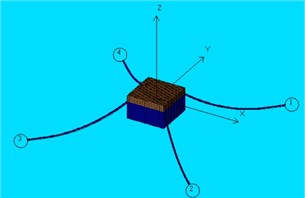
a) Rectangular box
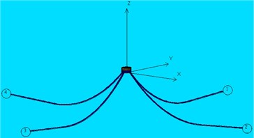
b) Cylinder
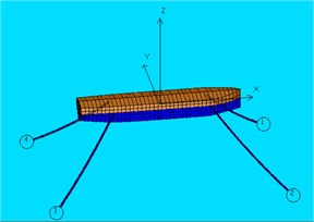
c) Immersed tunnel element
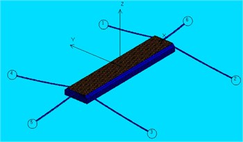
d) Ship
3. Simplified formula for calculating wave forces
The wave forces acting on the floating body can be decomposed into the lateral wave force and the longitudinal wave force . All the factors affecting wave forces are taken into consideration to establish a simplified formula of wave forces. The considered factors of wave height, wave direction, wave period, structural length, and draft are expressed as influence factor 1, 2, 3…, while all the other unconsidered factors are expressed as synthesis factor and , respectively.
3.1. Lateral wave force
3.1.1. Wave height
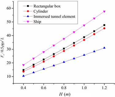
In Fig. 2 (a), -axis is the dimensionless lateral wave force divided by , is the wave amplitude, is the structural length. It can be seen that the dimensionless lateral wave force is increased with the increase of wave height, which is basically in direct proportion to the wave height. Therefore the influence factor can be given as:
where is the incident wave height.
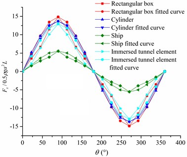
Fig. 2The effect of wave direction and wave height on lateral wave force
a) Wave height
b) Wave direction
3.1.2. Wave direction
In Fig. 2(b), one can see that the value of lateral wave force varies in sinusoidal curve with the increase of wave direction. Multiplying by each maximum value of numerical computing results to obtain fitted curves, it can be seen that the numerical curves coincide exactly with the fitted curves. Therefore the influence factor for symmetrical structure can be given as:
where is the incident wave direction.
3.1.3. Wave period
According to the theoretical study and experimental verification [6, 7] it can easily cause parametric rolling when the rolling period is nearly double the wave period. In Fig. 3, it can be seen that with the increase of , the dimensionless lateral wave force is increased, which reaches a maximum value at the point of 0.5, after that the its value attenuate. Making use of superposition principle to solve the differential equation by introducing frequency response function, the rolling amplification factor can be obtained. Thus, the influence factor can be given as:
where is the wave period, is the rolling period, is the rolling non-dimensional damping coefficient.
3.1.4. Structural length and draft
It is known that the lateral wave force is directly proportional to structural length and draft [7], thus the influence factor can be given as:
where is the length of structure, is the draft of structure.
By using Eqs. (4)-(7), and all the influence factors are multiplied by to maintain dimensional consistency, can be obtained as:
where is the dimensionless lateral synthesis coefficient.
3.2. Longitudinal wave force
Similarly, can be obtained as:
where is the dimensionless longitudinal synthesis coefficient, is the structural width, is the pitching period, and is the dimensionless pitching damping coefficient.
3.3. Determination of key parameters of simplified formula
It is noted that [7] and . A smaller value is chosen to make sure that the result is more safety, and then the fitting analysis for curves is carried to determine the value of .
Fig. 3Lateral colligation factor of simplified formula
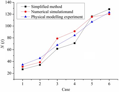
Fig. 4Validation of the simplified method
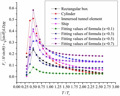
In Fig. 3, -axis is the dimensionless lateral wave force which is divided by . is increased accordingly, which reaches a maximum value at the point of 0.5, then the value of force attenuates. It is clear that the variation of the fitted value curves agree well with the numerical value curves. When the value of varies from 0.1 to 0.7, the numerical value curves can be wrapped by fitted value curves basically. So the value of varies from 0.1 to 0.7. Similarly, the value of varies from 0.1 to 0.7. In most cases, the values of and are recommended as 0.5. In the conservative case, they are recommended as 0.7.
4. Simplified method for calculating mooring forces
Then the standard value of mooring forces of mooring systems can be obtained as:
where is the standard value of mooring forces, is the non-uniform coefficient of distribution of force, is the angle between horizontal projection of mooring cable and -axis, is the angle between mooring cable and horizontal plane, and are the total lateral force and the total longitudinal force induced by wind, current and wave, respectively, and is the number of loaded mooring cables.
5. Validation of the simplified method
In Fig. 4, it can be shown that the results obtained by the proposed simplified method agree well with those obtained by numerical simulations and physical modelling experiments. In practice, the key parameters of formula can be chosen according to the specific circumstances of engineering application. Generally speaking, the conservative parameters are recommended.
6. Conclusions
Parameters study is made for the effects of wave parameters and structural parameters on wave forces. A simplified method for calculation of mooring forces is proposed. The results from the simplified method agree well with those from numerical simulations and physical modelling experiments. The proposed simplified method can be used to obtain the mooring forces easily and efficiently, but it still needs to be further improved.
References
-
Koo W. C., Kim M. H. Current effects on nonlinear wave-body interactions by a 2D fully nonlinear numerical wave tank. Journal of Waterway, Port, Coastal, and Ocean Engineering, Vol. 133, Issue 2, 2007, p. 136-146.
-
Li B. A 3-D model based on Navier-Stokes equations for regular and irregular water wave propagation. Ocean Engineering, Vol. 35, 2008, p. 1842-1853.
-
Prediction of Wind and Current Loads on VLCCs, 2nd Edition. OCIMF, Wither by and Co Ltd., London, 1994.
-
Ming-Chung Fang, Gung-Rong Chen On the nonlinear hydrodynamic forces for a ship advancing in waves. Ocean Engineering, Vol. 33, 2006, p. 2119-2134.
-
Dong G. H., Sun L., Zong Z., Zhao Y. P. Numerical analysis of the forces exerted on offshore structures by ship waves. Ocean Engineering, Vol. 36, 2009, p. 468-476.
-
Buchner B., Dijk A., Wilde J. Numerical multiple-body simulation of side-by-side mooring to an FPSO. Proceedings of 11th ISOPE, 2001, p. 343-353.
-
Sheng Zhen-bang, Liu Ying-Zhong Principles of Ship. Shanghai Jiao Tong University Press, Shanghai, 2009, (in Chinese).
About this article

The study is supported by the National Natural Science Foundation of China (11172333, 11272361). Such financial aids are gratefully acknowledged.
