Abstract
An analytical method to solve vibration of the propulsion shaft under hull deformation excitations is introduced. The model of shaft with the excitations at bearings is seen as a simplified propulsion shaft-ship hull system, as bearings could be assumed as the connection structures that transmit the forces from hull to shaft. The equations of shaft motion and continuity/boundary conditions are presented and hull excitations are included in the continuity conditions equations. Vibration characteristics of shaft under hull excitations are gained. The effects of propeller, supports stiffness, the location of hull excitations, the amplitude of excitations and the size of shaft are discussed.
1. Introduction
With the development of ship enlargement and economization, many researchers focus on the design of large ships and their propulsion systems [1]. For the ships with large size, dynamic interaction of propulsion shaft and ship hull is more and more evident, especially when it is travelling in rough seas [2]. Therefore, it is meaningful to work on the coupling interactions between the propulsion shaft and the ship hull in the sea wave during the analysis of vibration to guarantee the safety of navigation. Xing and Price used numerical methods to deal with the coupled fluid-solid interactions [3] to solve the effects between ship hull and sea wave. Qiu [4] simplified the ship as a beam and built a finite model to simulate a flexible beam in finite depth water under moving loads in the ship-shaft coupled analysis. Lech Murawski [5] analyzed the effect of hull deformation on the shaft alignment. Low and Lim [6] presented an approach to determine the changing displacement of the propulsion shaft due to the hull deflection. Tian [7] used a numerical two-dimensional model of large ship propulsion-hull coupling system to analyze the dynamic interactions of the vibration of the ship propulsion system and the vibration of the hull.
In the analysis of shaft vibration, the model of shaft is always composed of propeller, beam, and rotor. Warikoo [8] built a propeller shaft assembly, including blades and shaft rotor. Propeller could also be simplified as mass at the shaft end. Low [9] introduced a method to solve the natural frequencies of a beam-mass system in transverse vibration. Bearings, as the connection between propulsion shaft and ship hull, transmit the forces from ship hull to propulsion shaft. They could be assumed as discontinuities structures of the propulsion shaft. There are many researches on the shaft model including discontinuities. Shahgholi [10] studied the free vibration analysis of a shaft with simple support conditions. Wang [11] researched on the vibration of beams with arbitrary discontinuities and boundary conditions. Lin and Change [12] considered the model of multi-span beams with intermediate flexible constraints. Lin [13] utilized the numerical assembly method to solve mode of a multi-span Timoshenko beam with a number of concentrated elements, including masses, linear springs and rotation springs. Zhang [14] used a general analytical solution to study free vibration of non-uniform Timoshenko beams coupled with flexible attachments and multiply discontinuities in engineering application, based on separation of variable in conjunction with transfer matrix approach.
Based on these references, in this paper, a method to solve vibration of the propulsion shaft under hull deformation excitations is introduced. The model of shaft with the excitations at bearings is seen as a simplified propulsion shaft-ship hull system. Propeller is assumed as a mass at the end of the shaft. Added mass from the water around it is considered. Section 2 describes the equations of shaft motion and continuity/boundary conditions. Moreover, hull deformation excitations are considered in the continuity conditions equations at each support. The analytical solution of the propulsion shaft under hull deformation excitations is gained. In Section 3, a finite element model is developed in ANSYS to validate the results obtained from analytical model presented in this work. Dynamic responses of propulsion shaft are gained by analytical method to discuss vibration characteristics of the propulsion shaft under hull deformation excitations. The effects of propeller, supports stiffness, the location of hull deformation excitations, the size of the shaft and the amplitude of excitations are considered.
2. Dynamic model of a propulsion shaft under hull deformation excitations
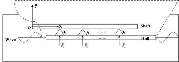
Bearings are assumed as the important connections between propulsion shaft and hull in the shaft-hull vibration system, which transmit the forces from hull deformation due to sea wave to propulsion shaft, as shown in Fig. 1. Thus, in this paper, propulsion shaft is simplified as a beam with hull excitations at the bearing supports. The propeller is considered as a mass at the end of the shaft. Except for loading on the bearings of shaft via hull deformation, sea wave affects the running of propeller. This influence is consisted of gravity effects, damping effects and inertia effects, of which inertia effects are the most important. Therefore, added mass on propeller due to water around it is introduced here.
As the hull deformation have great effects on the bending direction, axial vibration is ignored and 2-dimensional system of motion is considered. The shaft beam with length is divided into segments by n supports with lengths , ,…, respectively. The bearing supports , ,…, with stiffness , ,…, and the damping , ,…, respectively are modeled as intermediate flexible constraints.
Fig. 1Model of shaft-hull system
2.1. Equation of motion for propulsion shaft
For each segment of shaft beam, the bending dynamic equation of motion is as follows, according to the Euler-Bernoulli theory:
where is time. is mass density per unit length. is the Young’s modulus and density of the shaft. is the moment of inertia of each segment of shaft.
According to Clough [15], the displacement of shaft can be solved from Eq. (1) as:
where is generalized coordinate and:
is the mode function where . is the natural frequency. , , , are the coefficients of each segment.
2.2. Boundary conditions and continuity conditions
The continuities condition of displacement, slope, bending moment and shearing force at the junction of two segments across each support can be expressed respectively:
where denotes the left section of the beam on the support bearing , the right section of the beam on the support bearing . is the stiffness and is the damping factor of each support.
For the free-free shaft beam, the boundary conditions at each end are as follows:
When the propeller is considered as a mass at the end of the shaft, the boundary condition Eq. (5) at becomes:
where is the quality of the propeller mass and the added mass due to the water around it and is the moment of inertia of it. The relationship between added mass and propeller mass can be expressed approximately as [16]:
where is decided by the blade area ratio , when , , when , . is pitch ratio and is the number of blades.
2.3. Hull deformation excitations at the support
Hull deformation excitations are applied as harmonic point forces at the supports. The point force at is described in terms of Dirac delta function by:
where is the amplitude of the force. Thus, when the hull deformation excitation at the support is considered, excluding the time harmonic dependency, the continuity condition Eq. (4d) turns into:
2.4. Solution of propulsion shaft under the hull deformation excitation
According to Eq. (3), the displacements and forces of each part of shaft can be expressed in terms of . Thus, substituting Eq. (3) to continuity condition Eqs. (4a)-(4d) and boundary condition Eq. (6) and (7), the equations can be arranged in matrix form to solve the free vibration of the propulsion shaft with propeller as follows:
where is the vector of 4(1) unknown coefficients for 1 segments of shaft, which are given by:
For the th part of shaft, the matrix block of the displacements and forces are:
where , , or means the coefficient of th segment to , , or which can be gained by the continuity condition Eq. (4). The initial and final parts of the shaft are expressed in terms of displacements or forces, depending on the boundary conditions at each end of the shaft. One end with propeller mass and one free end are considered here by:
When the hull deformation excitations are considered, the matrix form solution of dynamic responses of the shaft with propeller is as follows:
The force matrix for the continuity condition refers to the hull deformation excitation at each support as:
while the force matrix for the boundary condition is:
Solving the system, the displacement of shaft at a certain frequency and the vibration characteristics can be gained.
3. Results for the dynamic response of the propulsion shaft
A simplified model of propulsion shaft of one typical ship with hull excitations at the bearings is presented in Fig. 2. The length of the shaft is 47.631 m and the radius is 0.3973 m. The right end (47.631) is connected to the engine while the left end ( 0) is the connected to the propeller, which is simplified as a mass with the quantity 92580 kg and the moment of rotary 896174.4 N∙m. The shaft is divided into five segments by four supports with lengths of 10.381 m, 7.750 m, 11.288 m, 10.250 m, and 6.962 m respectively from propeller end to engine end. The material properties for shaft are density per length 3380 kg/m, Young’s modulus 210 Gpa and Poisson’s ratio 0.3. The inertia moment of the shaft is 0.0196 m4. The stiffness of the four supports is 1.0 GN/m and the damping of supports from film and bearing is 0.5. The parameters of the propeller are quality 92580 kg, diameter 8.8 m, blade area ratio 0.96, pitch ratio 0.98 and the number of blades 6.
Fig. 2The model of the shaft
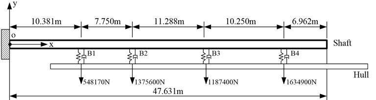
According to the ship real data and simulation, when the ship is in the case of sea wave length 319.98 m, wave direction 180°, wave height 10 m, amplitude of the hull excitations at supports are 548170 N, 1375600 N, 1187400 N and 1634900 N, respectively, which are also presented in Fig. 3. In this paper, this case is taken as an example to show how to use the mentioned analytical method to analyze the dynamic responses of a propulsion shaft under hull deformation excitations.
3.1. Accuracy of the analytical method
A finite element model is developed in ANSYS to validate the results obtained from the analytical model presented here. The shaft, the supports and the propeller are built by element Beam188, Combin14 and Mass21, respectively. The natural frequencies obtained from two methods are compared in Table 1, while the results of dynamic responses of the shaft under hull deformation excitations from both methods are shown in Fig. 3. The observed response point is 47.631, which is the engine end.
Table 1Comparison of natural frequencies by two methods
Analytical result (Hz) | FEA result (Hz) | |
1 | 5.64 | 6.07 |
2 | 6.42 | 6.37 |
3 | 15 | 14.93 |
4 | 18.15 | 18.05 |
5 | 23.73 | 25.43 |
6 | 26.5 | 26.28 |
7 | 35.52 | 35.53 |
8 | 39.95 | 40.00 |
9 | 48.14 | 48.26 |
10 | 55.64 | 57.97 |
From Table 1, The comparison between the analytical and FEA results indicates that the natural frequencies agree well for each mode, which means the solution of vibration from the analytical method introduced in this paper is reliable. Meanwhile, when the hull deformation excitations are considered, as shown in Fig. 3, the response displacements at the observed point using these two methods are also matching, except for some small errors at peaks or anti-peaks, especially at higher frequency range. These errors arise due to different precisions and solutions for two methods, which are more obvious when the vibration is more complex at higher frequency range. But the errors could be acceptable, as they have few effects on the analysis of the vibration characteristics.
Fig. 3Comparison of dynamic responses by two methods
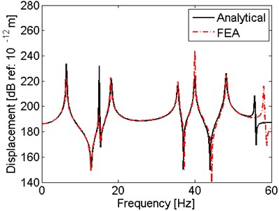
Fig. 4Dynamic responses of the shaft under hull excitations
3.2. Vibration characteristic of the shaft under hull excitations
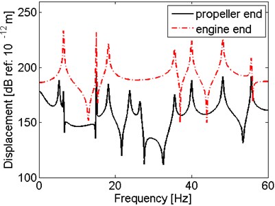
This part discusses the vibration characteristics of the shaft under the hull deformation excitations mentioned in the given case in the sea wave. The observed points are 0 (propeller end) and 47.631 (engine end), which are also discussed in following other parts. The response displacements at these two points under hull deformation excitations are presented in Fig. 4 and the response shapes of the shaft under the first 10 natural frequencies in Table 1 are shown in Fig. 5(a)-5(c).
It can be observed in Fig. 4 that the amplitude of displacement at the engine end is larger than that at the propeller end, due to the mass of propeller constrain the vibration. It also can be seen from the curves that the displacement of propeller reaches the peaks at every natural frequency while the excitations at 1st, 5th and 6th frequency do not excite the resonant vibration of the engine end. From Fig. 5, it is shown that the axial hemi-wave number is from 1 to 8 under the harmonic hull excitations under the first 10 natural frequencies. The shaft under the 10th frequency has largest deformation with the largest displacement 9.985 m at 19.8 m, which means that 55.64 Hz is the most dangerous frequency during 0-60 Hz frequency range when the shaft vibrates under these hull deformation excitations in this sea wave case. The second largest displacement occurs at the 6th frequency at 14.3 m, which is 5.576 m. Thus, at 26.5 Hz, 14.3 m is the most dangerous location.
Fig. 5Response shapes under hull excitations of natural frequencies
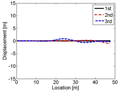
a) Shapes under 1st-3rd frequency
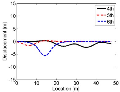
b) Shapes under 4th-6th frequency
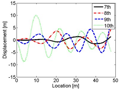
c) Shapes under 7th-10th frequency
3.3. Effect of the propeller
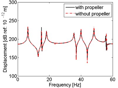
As the propeller is considered as a mass (propeller mass and added mass) at one end in this model, the effect of the propeller on the vibration characteristics of shaft under hull deformation excitations is discussed in this part. The response displacements at propeller end and engine end of the shaft with and without propeller mass are compared in Fig. 6.
As shown in Fig. 6, the mass of propeller has few effects on the response displacement at 47.631, which is because that the engine end is far from the propeller. But at , the displacement of the shaft with propeller mass is apparently smaller than that of the shaft without propeller. However, the peaks of the curve do not shift, which means the resonant frequencies has no change. To conclude, the propeller mainly constrains the amplitude of displacement of the response points near the propeller end.
Fig. 6Comparison of results for the shaft with and without propeller
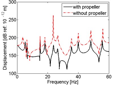
a) Displacement at
b) Displacement at
3.4. Effect of the stiffness of supports
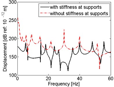
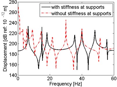
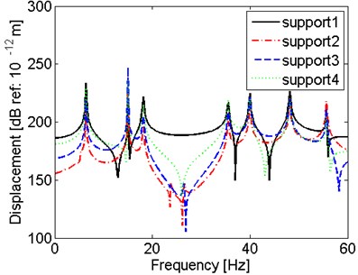
As the hull deformation excitations are set at the supports, this part discusses the effect of the stiffness of supports on the vibration characteristics of shaft under hull deformation excitations. The response displacements of the shaft with support stiffness 1.0 GN/m are compared with the results for the shaft without support stiffness (), which is shown in Fig. 7.
It is observed in Fig. 7 that compared with the results of shaft with stiffness, the peaks for the shaft without stiffness shift to left. In other words, the resonant frequencies decrease when there is no stiffness at the supports. Moreover, for corresponding peaks, the amplitude of the results for the shaft with stiffness are lower than that for the shaft without stiffness, especially at the lower frequency range, which is because there is less constraint for the no stiffness supports.
Fig. 7Comparison of results for the shaft with and without support stiffness
a) Displacement at
b) Displacement at 47.631
3.5. Effect of location of hull excitation
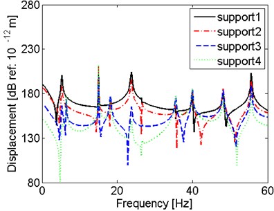
This part discusses the effect of the location of hull excitations on the vibration characteristics of shaft under hull deformation excitations. Set only one support is excited by hull deformation excitation only in this part. The amplitude of this excitation is the average of the hull deformation excitations, which is 1186517.5 N. Four cases are considered here, which are hull deformation excitation at support B1, B2, B3, and B4, respectively. The comparisons of these four cases are presented in Fig. 8.
It is observed in Fig. 8 that the location of hull deformation excitation has few effects on the resonant frequencies but have effect on the amplitude of the displacements. To be specific, at lower frequency range, the response displacement at is larger when the excitation is nearer to the propeller end. Similarly, the response displacement at 47.631 is larger when the excitation is nearer to the engine end. It means that the amplitude of the displacement is affected by both the location of the excitation point and the observed response point. But at higher frequency range, the amplitude is not affected by the location of observed response point, but mainly affected by the location of excitation point.
Fig. 8Comparison of results for the shaft with hull excitation at different support
a) Displacement at
b) Displacement at
3.6. Effect of the size of the shaft and the amplitude of hull excitations
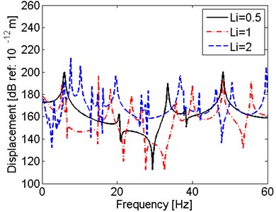
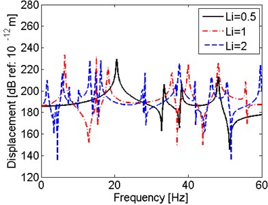
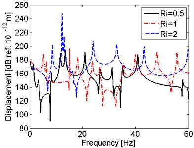
This part discusses the effect of the relationship between size of the shaft and amplitude of excitations on the vibration characteristics of shaft under hull deformation excitations. Firstly, effect of length and radius of the shaft are considered. Set and , where , are the length and radius of the original shaft and , are the length and radius of the shaft with changed size. The results of three shafts with different lengths are compared in Fig. 9 and the results of three shafts with different radiuses are compared in Fig. 10.
Fig. 9Comparison of results for the shaft with different length
a) Displacement at
b) Displacement at 47.631
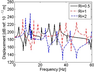
It is observed in Fig. 9 that the when the radiuses are equal, shaft with larger has lower first resonant frequency. Similarly, from Fig. 10, it can be seen that when the lengths are the same, shaft with smaller radius has lower resonant frequencies. To conclude, the slim shaft with long length and small radius is easy to have resonant vibration at lower frequency range.
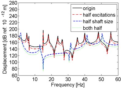
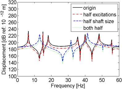
Then the size of shaft and the amplitude of excitations are considered at the same time. Four cases are considered. The first one is original model with hull deformation excitations described in Fig. 2. For the second case, the model is not changed but all the amplitudes of excitations are half. As to the third case, the size of the model is half, including the length and radius, but the excitations are still the same with those in Fig. 2. The last case is both the excitation amplitudes and shaft size are half. The comparisons of the results for these four cases are presented in Fig. 11.
Fig. 10Comparison of results for the shaft with different radius
a) Displacement at
b) Displacement at
Fig. 11Comparison of results for the shaft with different size and excitation amplitude
a) Displacement at
b) Displacement at
It is shown in Fig. 11 that for the same shaft model under excitations with different amplitude, the shape of the result curve and the location of the peaks have no change. Only the amplitudes of the displacement decrease when the amplitudes of excitations are lower. However, when the size of shaft reduces to half, the peaks of the curves move to left, which means the resonant frequencies are lower. To conclude, the amplitude of hull deformation excitation has effect on the amplitude of the displacement, while the size of the shaft affects on the resonant frequencies.
4. Conclusions
An analytical method to predict a propulsion shaft under hull deformation excitations at supports has been presented in this paper. The vibration solution of a shaft is gained by the bending equation of motion and the boundary/continuity condition equations. A model of a typical ship in a given wave case is built as an example. Good agreements between the analytical results and FEA results of the natural frequencies and dynamic responses are observed. The vibration characteristics of a propulsion shaft under hull deformation excitations are discussed. The effects of support the propeller, the stiffness of supports, the location of hull deformation excitations, the relationship between the size of the shaft and the amplitude of excitations are discussed. Conclusions are gained as follows:
1) Under the hull deformation excitations, the amplitude of displacement at the engine end is larger than that at the propeller end, due the mass of propeller constrain the vibration of the shaft. In the case mentioned in this paper, 55.64 Hz is the most dangerous frequency in the considered frequency range. The second largest displacement occurs at the 26.5 Hz and 14.3 is the most dangerous location.
2) The propeller mainly constrains the amplitude of displacement of the response points near the propeller end.
3) The shaft with supports stiffness has higher resonant frequencies and lower amplitude of response displacement than that of the shaft without supports stiffness.
4) The amplitude of the displacement is affected by both the location of the excitation point and the location of observed response point at lower frequency range but mainly affected by the location of excitation point at higher frequency range.
5) The slim shaft with long length and small radius is easy to have resonant vibration at lower frequency range. The amplitude of hull deformation excitation has effects on the amplitude of the displacement, while the size of the shaft has effects on the resonant frequencies.
References
-
Yang Y., Tang W., Ma J. Optimal design for a VLCC propulsion system based on torsional vibration analysis. Procedia Engineering, Vol. 15, 2011, p. 5378-5383.
-
Yan X. P., Li Z. X., Liu Z. L., et al. Study on coupling dynamical theory for interaction of propulsion system and hull of large ships: a review. Journal of Ship Mechanics, Vol. 17, Issue 4, 2012, p. 439-449.
-
Xing J. T., Price W. G., Wang A. Y. A transient analysis of the ship-water interaction system excited by a pressure water wave. Marine Structures, Vol. 10, Issue 5, 1997, p. 305-321.
-
Qiu L. C. Modeling and simulation of transient responses of a flexible beam floating in finite depth water under moving loads. Applied Mathematical Modelling, Vol. 3, Issue 33, 2009, p. 1620-1632.
-
Murawski L. Shaft line alignment analysis taking ship construction flexibility and deformations into consideration. Marine Structures, Vol. 18, 2005, p. 62-84.
-
Low K. H., Lim S. H. Propulsion shaft alignment method and analysis for surface crafts. Advances in Engineering Software, Vol. 35, Issue 1, 2004, p. 45-58.
-
Tian Z., Yan X., Li Z., et al. Dynamic interaction analysis of a propulsion shaft-ship hull system subjected by sea wave. Proceedings of the International Conference on Offshore Mechanics and Arctic Engineering – OMAE, San Francisco, CA, 2014.
-
Warikoo R., Haddara M. R. Analysis of propeller shaft transverse vibrations. Marine Structures, Vol. 5, Issue 4, 1992, p. 255-279.
-
Low K. H. Nature frequencies of a beam-mass system in transverse vibration: Rayleigh estimation versus eigen analysis solutions. International Journal of Mechanical Sciences, Vol. 45, 2003, p. 981-993.
-
Shahgholi M., Khadem S. E., Bab S. Free vibration analysis of a nonlinear slender rotating shaft with simply support conditions. Mechanism, and Machine Theory, Vol. 82, 2014, p. 128-140.
-
Wang J. L., Qiao P. Z. Vibration of beams with arbitrary discontinuities and boundary conditions. Journal of Sound and Vibration, Vol. 308, 2007, p. 12-27.
-
Lin H. P., Chang S. C. Free vibrations analysis of multi-span beams with intermediate flexible constraints. Journal of Sound and Vibration, Vol. 281, Issues 1-2, 2005, p. 155-169.
-
Lin H. Y. On the natural frequencies and mode shapes of a multi-span Timoshenko beam carrying a number of various concentrated elements. Journal of Sound and Vibration, Vol. 319, Issues 1-2, 2009, p. 593-605.
-
Zhang Z., Chen F., Zhang Z., et al. Vibration analysis of non-uniform Timoshenko beams coupled with flexible attachments and multiply discontinuities. International Journal of Mechanical Sciences, Vol. 80, 2014, p. 131-143.
-
Clough R. W., Penzien J. Dynamics of Structures. Computers and Structures Inc., University Ave. Berkeley, USA, 1995.
-
Luo C. The Research on Characteristics of Vibration and Underwater Radiated Noise of Shaft-Stern Coupled System. China Ship Development and Design Center, Shanghai, China, 2014.
About this article

All the work in this paper obtains great support from the State Key Program Grant of National Natural Science Foundation of China (No. 51139005).
