Abstract
This paper presents reliability determination of ignition system using the reliability block diagram and also, Failure Mode and Effect Analysis of ignition system is performed. This system is based on PLC controller to control the sequence of operation and electrical devices have a function to connect and disconnect the electrical circuit for supplying electric power for igniting the rocket. According to the complexity system, sometimes found that out of function such as misfire and hang fire. In this investigation, reliability block diagram of the ignition system include mechanical and electrical mechanisms is determined. By considering reliability of each component based on history of using, maintenance record, test report, and expert opinion and using ignition system reliability block diagram, reliability of ignition system can is determined. Moreover, since connector is the most important parts of ignition system by the highest RPN number. Hence, these parts must have a high reliability and have to more preventive maintenance and replace the new one after found the defect.
1. Introduction
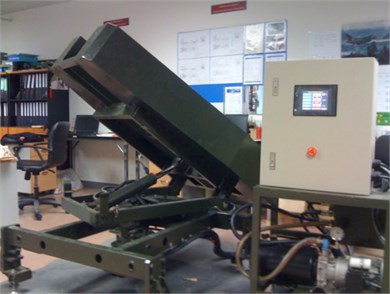
The ignition system is shown as Fig. 1 use for a rocket platform that is installed at Military vehicle laboratory in The Defence Technology Institute (Thailand). The half-scale rocket platform as shown in Fig. 2 consists of the turning mechanism, elevating mechanism, cradle, rocket pod, aiming system, and ignition system. The half-scale rocket platform has developed in laboratory and still improve the ignition system. The method have applied to develop the ignition system using failure mode and effect analysis and reliability block diagram to determine reliability of the ignition system.
Fig. 1Ignition system
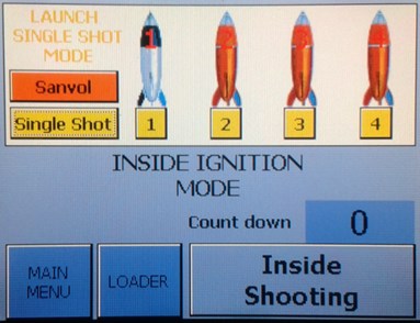
Fig. 2Rocket platform
Failure Mode and Effect Analysis: FMEA has been applied to use in various processes such as a product design process has been used this technique to design and develop the electric wire [1]. The process of reducing waste used it in producing water piping of the radiator in the car [2] and some cases use it to produce parts of the pressure gage [3]. Moreover, this method can also be applied to control the manufacturing process of the product to analyze and to control the metal level in jewelry production [4] and to improve and monitor the quality of housing builder [5]. Security management also applied this idea in their task. Some also used to develop their security system management in transportation of hazardous substance [6]. Project management also applied this concept in their task such as to find the method of quality assurance for water plant project [7]. FMEA itself has been developed this technique to have more accurate, precise and reliability. Also this paper presents this method to determine the risk of the ignition system to identify the risk and develop the ignition system for a half-scale platform of multi-launcher rocket as shown in Fig. 2.
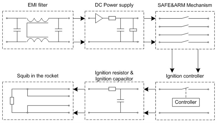
A reliability block diagram (RBD) is a diagrammatic method for showing how component reliability contributes to the success or failure of a complex system. The reliability block diagram is drawn as a series of blocks connected in parallel or series configuration. The ignition system has developed by applying this method to determine the reliability block diagram base on the block diagram of ignition system as shown in Fig. 3 and the schematic diagram of ignition system as shown in Fig. 4.
Fig. 3Block diagram of ignition system
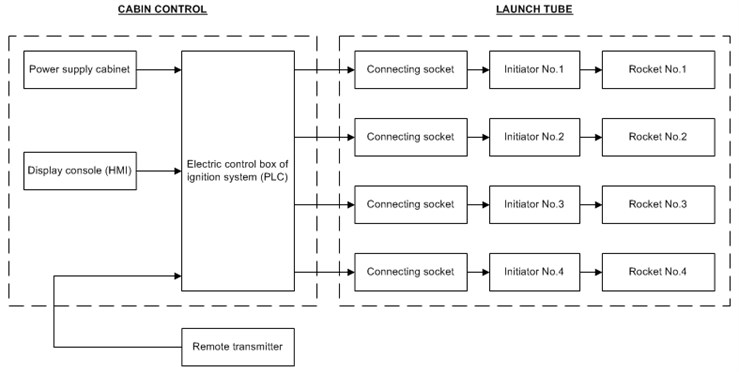
Fig. 4Schematic diagram of ignition system
2. FMEA analysis of the ignition system
A failure modes and effects analysis (FMEA) is a procedure in product development and operations management for analysis of potential failure modes within a system for classification by the severity and likelihood of the failures. This paper presents this method to determine the risk of the ignition system. It is widely used in manufacturing industries in various phases of the product life cycle and is now increasingly finding use in the service industry. Failure modes are any errors or defects in a process, design, or item, especially those that affect the customer, and can be potential or actual. Effects analysis refers to studying the consequences of those failures.
The risk priority number (RPN) [8] identifies the greatest areas of concern. It comprises the assessment of the:
1) Severity rating,
2) Occurrence rating, and
3) Detection rating for a potential failure mode:
Table 1The Failure mode and effect analysis
Project: DTI-1.2B | Failure Mode and Effect Analysis | Ignition system | ||||||
Configuration item | Explanation and function | Potential failure mode and effect | Severity | Potential cause(s) / mechanism(s) of failure | Occur | Current design controls detection | Detect | RPN |
Battery | Battery 2x24 V are separated from battery of the truck. This battery are supplied the electric power for device and the ignition system | The electric power not enough | 3 | Low battery and power not enough for ignition system | 1 | Mounty preventive maintenance and recharge the battery | 2 | 6 |
Power supply | Battery 2x24 V are separated from battery of the truck. This battery are supplied the electric power for device and the ignition system | No water, no electric power | 3 | Low battery and power not enough for ignition system | 2 | Mounty preventive maintenance and recharge the battery | 2 | 12 |
PLC | Control the sequence of ignition operating and programming the software | PLC cannot operate because no electric power, and the PLC is hang while operation | 3 | Program error and operator error | 1 | Self-testing and training the operator | 3 | 9 |
Selector switch | Open and close the circuit of each circuit of the ignition system | No electric power for igniting the rocket | 4 | Selector switch was loosen or broken | 2 | Preventive maintenance and replace the new one | 2 | 16 |
Safety mechanism | Open and close the circuit of each circuit of the ignition system | No electric power for igniting the rocket, and unsafety for operation | 4 | Safety mechanism was loosen or broken | 1 | Preventive maintenance and replace the new one | 2 | 8 |
Relay | Open and close the circuit of each circuit of the ignition system following the PLC | No electric power for igniting the rocket | 4 | Relay is short or loosen | 2 | Preventive maintenance and replace the new one | 2 | 16 |
Cable | Connect the circuit of the ignition system | No electric power to igniting the rocket | 4 | Disconnect or loosen, make to no electric power for igniting the rocket | 1 | Preventive maintenance and check loop resistance | 2 | 8 |
Connector | Connect the power supply to squid for igniting the rocket | Many time of usage and cracks on the connector | 4 | Disconnect or loosen, make to no electric power for igniting the rocket | 3 | Check the connector and check the loop resistance. If found the defect have to change the new one | 3 | 36 |
Squib | Igniting the rocket | Out of order | 4 | The squib is damage or out of order | 2 | Loop resistance check | 2 | 16 |
Rocket | The composite rocket | Hang fire | 4 | Low quality control in production | 1 | In process quality control | 3 | 12 |
The ignition system of the multi-launcher rocket system is consisted of battery, power supply, PLC, selector switch, safety mechanism, relay, cable, connector, squib, and rocket. Then use FMEA to analysis for all components as shown in Table 1 and calculate the RPN number follows Eq. (2) for each item. According to the calculation of RPN number of ignition system found that the connector, selector switch, relay, and squib have the highest RPN number respectively. Consequently, more attention should be considered in their design and preventive maintenance plan.
3. Reliability block diagram
A reliability block diagram (RBD) is a diagrammatic method for showing how component reliability contributes to the success or failure of a complex system. The reliability block diagram is drawn as a series of blocks connected in parallel or series configuration. Each block represents a component of the system with a failure rate. Parallel paths are redundant, meaning that all of the parallel paths must fail for the parallel network to fail. By contrast, any failure along a series path causes the entire series path to fail [9].
Accordingly, reliability of a series network [8] shown as Fig. 5 could be calculated as follows:
For reliability of a parallel network [8] shown as Fig. 6 could be calculated as follows:
Fig. 5Reliability calculation of a series network [8]
![Reliability calculation of a series network [8]](https://static-01.extrica.com/articles/16419/16419-img5.jpg)
Fig. 6Reliability calculation of a parallel network [8]
![Reliability calculation of a parallel network [8]](https://static-01.extrica.com/articles/16419/16419-img6.jpg)
Fig. 7Reliability block diagram of ignition system
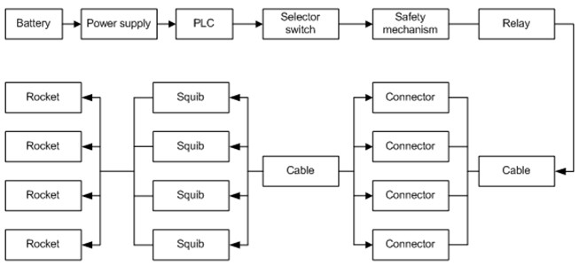
The ignition system is consisted of electrical component and mechanical components such as battery, power supply, PLC, selector switch, safety mechanism, relay, cable, connector, and squib. Also the reliability block diagram of the ignition system could be performed as shown in Fig. 7. In this diagram, it is obvious that those components which are series in the block diagram should have higher reliability, because failure of them causes failure of the whole process. This reliability block diagram can be used to determine reliability of the ignition system.
4. Numerical analysis
In order to determine reliability of the ignition system, its reliability block diagram is used. The reliability of all components is determined based on history of using, maintenance record, test report, and expert opinion and are shown in Table 2.
Reliability of the ignition system can be calculated as follows:
Thus it can be seen in Eg. (4), reliability of the ignition system is 87.436 %.
Table 2Reliability of ignition system components
Component | Reliability (%) |
Battery | 98.5 |
Power supply | 98 |
PLC | 98.5 |
Selector switch | 98 |
Safety mechanism | 99.7 |
Rely | 98 |
Cable | 98 |
Connector | 97 |
Squib | 99.1 |
Rocket | 99.5 |
5. Conclusions
The reliability determination of ignition system using the reliability block diagram and also, failure mode and effect analysis of ignition system is performed. The reliability of all components is determined. In this investigation, reliability block diagram of the ignition system include mechanical and electrical mechanisms is determined. By considering reliability of each component based on history of using, maintenance record, test report, and expert opinion and using ignition system reliability block diagram, reliability of ignition system can is determined. Moreover, since connector is the most important parts of ignition system by the highest RPN number. Hence, these parts must have a high reliability and have to more preventive maintenance and replace the new one after found the defect.
References
-
Chawanapronee Nipon The Application of FMEA and FTA in Product Design of An Electric Wire. Dissertation, Chulalongkorn University, 1971.
-
Buaklum Nattapon The Analysis and Reduction of Waste in the Manufacturing Process of Piping in the Radiator by Using FMEA. Dissertation, Chulalongkorn University, 2006.
-
Manyanong Surakit The Application of FMEA to Reduce Waste in Pressure Gage Manufacturing. Dissertation, Chulalongkorn University, 2007.
-
Lowakit Piyaporn A Study of Analysis and Control Precious Metal Level in the Process of Jewelry Production by Using FMEA. Dissertation, Chulalongkorn University, 2007.
-
Sangunsai Hatairat Development and Monitoring the Quality of Home Builder Process by Appplying QFD and FMEA. Dissertation, Chulalongkorn University, 2007.
-
Buddhapornmongkol Kitipong Security Management System for Hazardous Material Transportation by Risk Analysis. Dissertation, Chulalongkorn University, 2005.
-
Navalumlerd Thawatchai The Quality Assurance for Project Management of Water Plant. Dissertation, Chulalongkorn University, 1999.
-
Gorgin Rahim, Ali Farsi Mohammad Reliability determination of a sounding rocket separation system using its reliability block diagram and FMEA analysis of its spring system. The Proceedings of 2nd Iranian Conference on Reliability Engineering, Reli, 2011.
-
Wang W., Loman J. M. Reliability block diagram simulation techniques applied to the IEEE Std. 493 standard network. IEEE Transaction on Industry Applications, Vol. 40, Issue 3, 2004.
About this article

