Abstract
Compared with the traditional fixed test and auxiliary measurement ship, the measurement of the underwater radiated noise by using a vessel’s own towed array has many advantages, such as flexible, convenient, low cost, and so on. In this paper, the previous researches on this method are summarized. From the view of implementing this technique, the method has been divided into four aspects: towed array design, U-turn manoeuvre, underwater sound propagation and towed array signal processing. Overall, this technology is practical and feasible, and has a good application prospect. Next, combined with a large number of experiments, further study on the selected principle of the towed array and U-turn technical indicators will be done.
1. Introduction
During the voyage of ships, they will radiate noise into water. For military surface vessels and submarines, the characteristic of the underwater radiated sound is an important index to evaluate its stealth performance [1, 2]. At present, the traditional method of radiated noise measurement of naval ships is mainly divided into two kinds of fixed and portable [3, 4].
The fixed method is the test field which is built in specific water zone. The radiation noise is measured by using the hydrophone array which is fixed at the bottom of the sea. As the testing system is fixed, this method has high measuring accuracy. But the investment is large, and the cost of use and repair is highly.
The portable method is an underwater acoustic measurement system deployed to the particular water zone, based on auxiliary measurement ship. In Fig. 1, two typical types of portable measurement methods are given. There are the towed type and the delivered type, respectively. The former is the hydrophone array put to the specified location by using tow cable, as shown in Fig. 1(a). The latter is the hydrophone array delivered to the specified location by the ship, as shown in Fig. 1(b). The main difference between the two types is that the former is wire transmission, while the latter is wireless transmission.
Fig. 1The layout of two typical types of portable measurement method
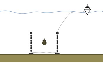
a) The layout of the towed type
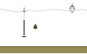
b) The layout of the delivery type
The traditional methods of underwater acoustic measurement are usually used for ship standard examination and acoustic experiment in specific water area. The fixed method has a high requirement of the environment and assistant facilities. The portable method is not easy to be fixed, so that it is affected by the environment and the measurement ship. All these measurements can’t be applied in any commonly ocean environment [5]. When vessels carry out missions (such as Cruise, campaign and so on) to a strange sea at short notice, the traditional methods can’t effectively achieve the radiated noise measurement. It is not conducive to the assessment of the current stealth trend of the vessel, as well as the success rate of the implementation of the missions.
At this time, using vessel’s own towed array to measure radiated noise can solve the problem perfectly [6, 7]. Military surface vessels and submarines commonly tow arrays of hydrophones for the detection and tracking of other vessels. Ships can use the towed array to measure its own radiation noise during the through the specific manoeuvre, such as U-turn. The implementation of this method does not require the cooperation of other measuring ship or the testing system. It is simple in structure, practical and low cost. When a ship reaches a certain sea area, it can be used to provide a reference for the current stealth trend of the vessel.
In this paper, the previous researches on using the vessel’s own towed array to measure the underwater radiated noise are summarized. From the view of technical point, the method has been discussed by being divided into four aspects: towed array design, U-turn manoeuvre, underwater sound propagation and towed array signal processing. It provides a basis for the further work to use this method to measure vessel’s own radiated sound.
2. Towed array design
In order to measure radiation noise by using its own towed array, one first has to know the basics of the towed array. Towed line array, towed array for short, can be divided into four parts: a line array, cable, laying and retracting device and electronic equipment. Fig. 2 shows the typical device of a towed array.
Fig. 2The typical layout of a towed array
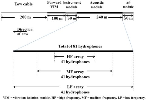
As shown in Fig. 2, it is composed of a tow cable, forward VIM, instrument module, acoustic module and aft module. The forward VIM has the buffer and the vibration isolation effect of the towed array. The instrument module is used to measure environment parameters for acoustic calculation through temperature sensor, deep sensor, etc. The acoustic module is the main part of towed line array, with tens or hundreds of hydrophones arranged at regular intervals. The aft module, in addition to vibration isolation, increases the resistance to keep the state of the array.
Besides, Fig. 2 shows a diagram of a generic towed array [8]. The array has a total of 81 hydrophones arranged in three sub-arrays, each comprising 41 hydrophones. The total number of hydrophones and associated processing channels is minimized by designing the acoustic section so that some hydrophones are common to two or three sub-arrays. The signal reception of different frequency bands can be identified by different length of the sub-array, so it is important to choose a suitable hydrophone array. Generally, the design frequency is the frequency at which the hydrophone spacing is half a wavelength.
As early as 1950s, several tests have been conducted from submarines and surface ships at various locations at sea [9-11]. The results provided establishment of “Towflex principles”. Besides, Lasky [12] pointed out that the background noise of a towflex array is seen to depend upon the cablescope, speed, directivity, sea state(at higher frequencies), external changes (weights, drag devices), and internal changes in array construction(at lower frequencies).
3. U-turn manoeuvre
After the type of towed array is determined, ships need special maneuver to measure the underwater radiated noise by suing the towed array. This is mainly because the towed array directly dragged behind the tow-ship, signal reception has the blind zone on the bow. At present, the studies have shown that the U-turn can solve this problem.
Duncan [13] has studied the towed array hydrodynamic simulation, in order to estimate the towed array during manoeuvers of the tow-vessel. The main idea is that the towed array was modeled as a series of nodes containing the array mass, connected together by mass-less springs. Based on the analysis of forces acting on each segment, the effects of changing various simulation parameters were tested. The result showed that the vessel speed had little effect on the array path. The simulation results are plotted in Fig. 3.
Fig. 3The simulation output for one manoeuvre by Duncan
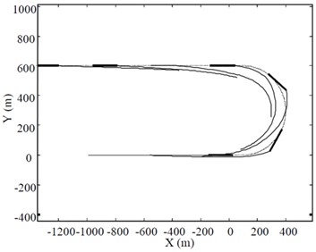
a) The simulated towed array shape during a U-turn manoeuvre
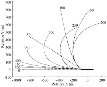
b) The simulated towed array shape relative to the tow vessel
Fig. 3(a) shows six snap-shots of the simulated towed array shape during a U-turn manoeuvre. Thin line is towed array, dotted line is vessel track, and thick line is vessel. Simulation starts with vessel at (0, 0) and moving to the right. Vessel speed = 5 m/s, turn radius = 300 m, tow cable length = 400 m. Fig. 3(b) shows the position of the acoustic module of the array relative to the vessel during the same manoeuvre as in Fig. 3(a). Thin line is acoustic module, broken line is remainder of array, and thick line is tow vessel. Numbers are time in seconds from start of simulation.
By using a coupling dynamical model for a towed array system, Zeng et al. [14] predicted the array position relative to the submarine and the lineup of the towed array during U-turn and circular maneuvers. From this, the relationships between the towed array position and the submarine’s velocity, rudder angle and cable length were predicted. The research indicates that, when maneuvering in circles, a steady position of the towed array can be maintained, and that rudder angle and cable length have great influence on the position of the towed array while the submarine’s velocity has little influence.
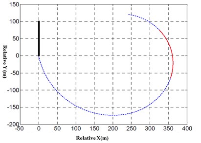
As shown in Fig. 4, Duncan [15] compares the performance of different beamforming algorithms in a scenario where the tow-vessel executes a constant radius turn. This scenario has the advantage of allowing longer integration times than the U-turn manoeuvre. In Fig. 4, the thick black line is the centre-line of the tow-vessel and the solid red line is the acoustic section of the array.
Fig. 4Steady-state horizontal plane array shape relative to tow-vessel
Zhu et al. [16, 17] used a practical towed cable-array system to investigate behavior on turning maneuvers. The results of the simulation shows that drop-down phenomenon happened while turning angle velocity is under about 0.007 rad/s.
According to maneuver equation, Liu et al. [18] predicted the motion of ship during turning maneuvers, and got the velocity of ship at the first node of the cable. The velocity was taken into the code of towed cable-array system simulation as boundary condition. The result was used to investigate the behavior of the cable during turning motion of ship and the influence of ship’s turning maneuvers on the cable is discussed.
Wan et al. [19] makes use of the standard LM algorithm to predict the position of array. By analyzing the difference between the position of prediction and true, they indicate that the maximum error of prediction is occurred at both ends of array, and the LM algorithm can predict the position of towed array according to the information generated by itself.
4. Underwater sound propagation
Underwater acoustic signal travels from the sound source, through the sea channel, to the receiving array. The sources of noise are produced mainly by submarine propulsion (propeller noise), mechanical noise and environmental impact. The simulation of mechanical noise is realized by the superposition of sinusoidal harmonic signals with different phase and amplitude. The model is described below [20]:
here is the number of line spectrum, is the number of harmonics, is amplitude, is the phase difference, is a random variable, is uniform random variable.
Propeller noise has been simulated by superimposing the broadband noise and modulation line spectrum noise, and by considering the ocean ambient noise and the noise of wind-driven current [21], based on Mellen’s experimental results and Ross’s noise model [22]. According to the noise model of Ross, the peak frequency and the sound pressure structure above 100 Hz can be expressed as:
here, is the number of cavitation blades, is the tip cavitation index, is the real cavitation index, is the flow velocity of critical cavitation, is the flow velocity, is sound speed.
At present, there are many existing models for sound propagation. The models mainly divided into ray model, normal model, multipath propagation model, fast field model, parabolic equation model and some hybrid algorithms [23]. Different models have their own advantages and disadvantages and applicable scope, so different methods should be chosen for solving different problems. Since the towed array radiated noise measurement is measured in the ocean around the ship, the horizontal change of the environment can be ignored. The vertical variation of the ocean environment has great influence on acoustic propagation. Here, the virtual source method is applied to describe sound propagation. The transmission loss is:
here, is the distance from the source to the receiver, the distance from the image source to the receiver.
Signal processing of the towed hydrophone array is complex, which will be described in detail in the next section.
5. Towed array signal processing
Signal processing of the towed hydrophone array is one of the key technologies for measuring the underwater radiation noise. The basic steps of array signal processing are given [24].
1) Fourier transform the received signal on each hydrophone and combine the results at each frequency in a complex column vector , with one element corresponding to each hydrophone.
2) Compute the direct-path distance between the desired focal point and each hydrophone.
3) Calculate the corresponding phase change, , at each frequency. Here is the hydrophone number and is the frequency.
4) Form the steering vector, where the superscript represents the transpose operator.
5) The beam output is then given by: where the superscript represents the Hermitian transpose (complex conjugate of the transpose).
Cheng et al. [20] design a method for source localization measurements via a constant radius turn manoeuvre by using submarine’s towed hydrophone array. Meanwhile, MVDR (Minimum Variance Distortionless Response), Spatially Smoothed MVDR and BMUSIC algorithms is adopted for beamforming. Then, different sources with a short distance can be separated in the range of special frequency band.
For this technology, the directivity and localization of radiated sound source need to be further improved.
6. Conclusions
In this paper, firstly by comparing with the traditional methods, it is low cost, flexibility and strong adaptability for a vessel to measure underwater radiation noise by using vessel’s own towed array. Then, the previous researches on this method are summarized. From the view of implementing this technique, this method has been divided into four aspects: towed array design, U-turn manoeuvre, underwater sound propagation and towed array signal processing. At present, the technology is not very mature, most of the research is still in the theory, simulation and a small amount of field measurement. Overall, a lot more work is still required, such as the selected principle of the towed array, U-turn technical indicators, ocean environmental parameter settings, etc. On the basis of previous works, further research on this technology will be done.
For this technology, the directivity and localization of radiated sound source need to be further improved.
References
-
Li N. Development trend and analysis of the foreign naval ship stealth technology. Journal of Ship Electronic Engineering, Vol. 33, Issue 4, 2013, p. 15-17.
-
Wang Y., Lu K. M., Yu G. P., et al. Present situation and development of noise control for submarines abroad. Journal of Ship Electronic Engineering, Vol. 31, Issue 1, 2010, p. 1-4.
-
Wang Z. C., Chen Z. Q., Yu F., et al. Warship Noise Measuring and Analyzing. National Defense Industry Press, Beijing, 2004.
-
Bingham B., Kraus N., Howe B., et al. Passive and active acoustics using an autonomous wave glider. Journal of Field Robotics, Vol. 29, Issue 6, 2012, p. 911-923.
-
Meng X. Y., Xiao G. L., Chen H. Review of the present situation and development of acoustic stealth technology for submarines abroad. Ship Science and Technology, Vol. 31, Issue 11, 2011, p. 135-139.
-
Edmund J. S. Model-Based Processing for Underwater Acoustic Arrays. ASA Press, USA, 2015.
-
Heidemann J., Stojanovic M., Zorzi M. Underwater sensor networks: applications, advances, and challenges. Philosophical Transactions of the Royal Society A, Vol. 370, 2012, p. 158-175.
-
Duncan A. J., Penrose J. D. Measurement of Radiated Noise, Using a Vessel’s Own Towed Array – a Progress Report. 2000.
-
Fitzgerald J. W., et al. Principles and Applications of Towflex Hydrophones. Project Toad, Part I, Chesapeake Instrument Corporation Report, 1960.
-
Eder J. P. Investigation of the Near Field Noise of USS ALBACORE (AGSS 569) Using a Towed-Flexible Hydrophone Array. David Taylor Model Basin Report 1193, 1960.
-
Sykes A. O. The Experimental Evaluation of a Towed Flexible (TOWFLEX) Hydrophone Array. David Taylor Model Basin Report 1314, 1961.
-
Lasky M., Doolittle R. D., et al. Recent progress in towed hydrophone array research. IEEE Journal of Ocean Engineering, Vol. 29, Issue 2, 2004, p. 374-387.
-
Duncan A. J. The Measurement of the Underwater Acoustic Noise Radiated by a Vessel Using the Vessel’s Own Towed Array. Curtin University of Technology, 2003
-
Zeng G. H., Zhu J., Ge Y. J. Predicting the position and analyzing the parameters of a towed array during the maneuvering of a submarine. Journal of Harbin Engineering University, Vol. 30, Issue 7, 2009, p. 723-727.
-
Duncan A. J., Mcmahon D. R. Using a towed array to localise and quantify underwater sound radiated by the tow-vessel. Proceedings of Acoustics, Gold Goast, 2004.
-
Zhu J., Liu J. Towed cable-array system simulations on turning manoeuvers. Journal of Naval University of Engineering, Vol. 13, Issue 4, 2001, p. 22-28.
-
Zhu J., Pang Y. J., Xu Y. R. Numerical simulation of vibrating behaviors using towed cable-array. The Ocean Engineering, Vol. 21, Issue 5, 2003, p. 76-81.
-
Liu J., Lin C. Y., Zhu J. Prediction of towed cable-array system’s position during turning maneuver of ship. Journal of Naval University of Engineering, Vol. 14, Issue 2, 2002, p. 80-84.
-
Wan W. B., Zhu J., Cao L. S. Predicting the position of a towed array during the steady turning of ship. Ship Electronic Engineering, Vol. 33, Issue 8, 2013, p. 148-150.
-
Cheng G. T., Zhu J., Zheng G. H. A simulation of radiated noise detection based on towed array. Technical Acoustics, Vol. 28, Issue 4, 2009, p. 472-475.
-
Ross D. Mechanics of Underwater Noise. Pergamom Press, New York, 1976, p. 350-380.
-
Etter P. C. Underwater Acoustic Modeling. Elsevier Applied Science, Spon Press, New York, 1991, p. 110-155.
-
Lu X. T., Zhang L. Review of sound propagation modeling in underwater warfare environment. Ocean Technology, Vol. 29, Issue 4, 2010, p. 48-53.
-
Duncan A. J., Mcmahon D. R. Using a towed array to characterize the underwater acoustic noise radiated by the tow-vessel. Acoustic 2002-Innovation in Acoustics and Vibration Annual Conference of the Australian Acoustical Society, Adelaide, Australia, 2002, p. 165-175.
About this article

