Abstract
In the process of measuring the radiated noise of underwater structure, using optical fiber hydrophone array is the main means of information acquisition. Due to the complexity of the measurement environment, when the wavelength of the light source and the array deformation in the optical fiber measurement system are changed, the power fluctuation of the input light and the demodulation failure of the system will be caused, which will affect the measurement effect of the radiated noise. For this reason, an adaptive control system for the optical source and the demodulator is designed, which can ensure the stability of the laser source and the digital demodulation system. The experimental data show that the adaptive control system designed in this paper can realize signal stable modulation and signal synchronous processing, which provides a more suitable scheme for accurate measurement of underwater equipment radiated noise.
1. Introduction
Optical fiber hydrophone has the advantages of high sensitivity, good integration, strong anti-electromagnetic interference and anti-signal crosstalk. Therefore, in the measurement of radiated noise of underwater equipment, optical fiber hydrophone array is widely used as noise measurement sensor, and optical fiber is used as transmission channel for signal transmission. In order to extract the acoustic detection signal of each element of the optical fiber hydrophone array, the modulated optical signal is usually converted into electrical signal, and then the digital acoustic signal of the target is finally obtained by demultiplexing and PGC demodulation [1]. Photoelectric signal conversion is mainly realized by photoelectric conversion module, but when the input light intensity is too large, the module will produce saturation phenomenon, and the correct signal can’t be obtained by collecting and processing at the back end; when the input light intensity is too weak, the self-noise generated by demodulation will be very high due to low signal-to-noise ratio [2]. In addition, the actual optical fiber hydrophone detection system because of its complex use environment, optical fiber source wavelength drift, array deformation, resulting in input light power fluctuations, affecting the stability and reliability of the detection system. However, the anti-shock ability of large-scale array acquisition and regulation system is limited. Generally, it can only process signals with small amplitude change, and the demodulation system will be invalid if the signal is too strong or weak. Therefore, in order to adapt to the change of the input optical power, the photoelectric preamplifier adaptive gain adjustment system is introduced into the acquisition and demodulation system to ensure the stability of the output signal amplitude, thus improving the accuracy and effectiveness of the optical fiber hydrophone array for underwater equipment radiation noise measurement.
2. Basic control principle of AGC
According to the characteristics of the optical fiber amplifier, the optical fiber amplifier is used to keep the output signal in the constant range. The basic principle is [3-5]: when the collected optical power signal exceeds the maximum limit, the preamplifier gain is reduced to keep the signal amplitude in an effective range; when the optical power signal is lower than the minimum limit, the preamplifier gain is increased and the signal-to-noise ratio of the input signal is increased. The implementation principle is shown in Fig. 1, When the input signal is small (), the output signal increases with the increase of input signal. When the input signal is greater than , the output signal reaches the threshold value . At this time, the AGC gain decreases, so that the amplitude of the output signal is always kept below the threshold . As the amplitude of input signal continues to increase, the output signal will show clipping distortion when it exceeds .
Fig. 1The schematic diagram of AGC control
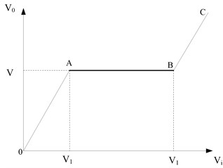
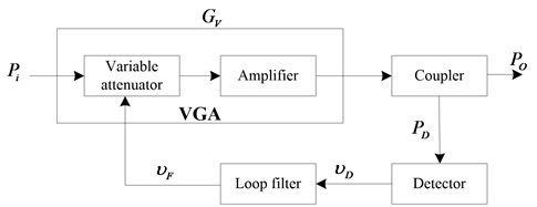
Fig. 2The AGC model
3. AGC mathematical model
According to the above analysis principle, a digital circuit suitable for gain adaptive control of photoelectric preamplifier is designed, as shown in Fig. 2. It is mainly composed of adjustable attenuator, amplifier, coupler, detector and loop filter.
The gain of the variable gain amplifier (VGA) is expressed as follows:
where is the VGA control accuracy, is the output voltage of the loop filter to control the VGA gain, and is the VGA gain with the control voltage of 0 mV. If the input and output voltages of AGC Based Active integral loop filter are and respectively, and the reference voltage is , then:
If the insertion loss of the coupler is set to 0 and the coupling degree is , the output detection voltage can be expressed as:
where is the detection accuracy of the detector, is the input level of the detector, and is the detection voltage when the input level of the detector is 0 dbm.
From the above analysis, the output of AGC circuit is expressed as follows:
The input of the geophone can be expressed as:
Eq. (5) is the mathematical model of AGC circuit in time domain [6, 7].
Carry out Laplace transform. It can be obtained that:
Eq. (6) is the mathematical model of AGC control circuit after Laplace transformation, where represents the closed-loop transfer function of loop filter. By solving this problem, we can get the following results:
In Eq. (7), is the closed-loop transfer function of AGC control circuit; represents the relationship between AGC control voltage and input level variation.
4. Hardware system design
Based on the above principle analysis, a gain adaptive adjustment system of optical fiber array optical preamplifier based on AGC is designed, as shown in Fig. 3.
Fig. 3The block diagram of adaptive gain adjustment principle
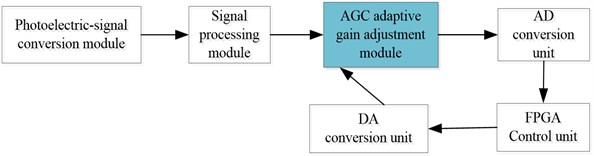
The realization principle of the adaptive control system is [8, 9]: the optical and electrical signals are converted by the photoelectric conversion module, and then the converted electrical signals are preliminarily amplified by the signal processing module to improve the anti-interference ability. Through AGC gain control, the output signal is guaranteed to be within the threshold range. The acoustic signal passing through the AGC adaptive gain adjustment module is sent to the high-performance FPGA gain control unit after passing through the AD conversion unit. The FPGA control unit detects the output of the AD conversion unit. When the output value is greater than the high threshold value of AGC, the gain is automatically reduced to prevent clipping distortion; when the output of the AD conversion unit is less than the pre-set value, the gain is reduced automatically When the threshold value is set low, the gain will be increased automatically to make the peak value of the output signal in the effective working range. In this way, FPGA control unit, AGC adaptive gain adjustment module, AD conversion unit and DA conversion unit constitute a closed feedback system. FPGA control unit detects the output of AD conversion unit, and then adjusts the gain of AGC adaptive gain adjustment module through feedback, so as to realize the function of adaptive gain adjustment of photoelectric preamplifier and ensure the stability and reliability of signal modulation and demodulation.
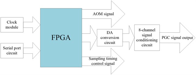
Due to the large amount of signal processing data and high real-time requirements of the optical fiber array test system, especially including multi-channel signals, the synchronous processing requirements of signal processing are higher. In order to realize the synchronous acquisition and control of all boards and cards, the synchronous control function is designed, and the high-performance FPGA is used as the core for AD sampling timing signal control [10]. The principle block diagram of synchronous control module is shown in Fig. 4.
Fig. 4The block diagram of synchronization control module
5. System testing
5.1. Light source signal modulation test
According to the research and analysis of the light source control technology and the design of the modulation and amplification system, in order to verify the performance of the light source modulation and amplification system, the light source signal PGC modulation is carried out with 128 kHz, and the modulation result is shown in Fig. 5.
Fig. 5The result of light source PGC modulation
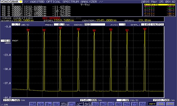
It can be seen that the output wavelength is stable and matches the wavelength of fiber array. The phase noise test of the light source near 1530 nm is shown in Fig. 6.
The measurement results show that the background noise of the demodulated noise spectrum at 1 kHz can reach –110 dB with good frequency response, which can meet the design requirements of optical fiber hydrophone array light source.
5.2. Signal processing synchronization test
In order to fully test the synchronization of the synchronization control module, the clock synchronization signal of the first ad of the first ad board is selected as the reference, and the oscilloscope probe is connected. Another input channel of the oscilloscope is used to measure the clock synchronization signals of other ad cards of the first ad board and the clock synchronization signals of each ad of other boards. The deviation of clock synchronization signals between different ad is measured, and the measurement data is recorded in Table 1. The delay test diagram of AD2 of board 1 and AD1 of board 2 relative to AD1 of board 1 is shown in Fig. 7.
Fig. 6The translation of phase noise test diagram of light source near 1533.56 nm
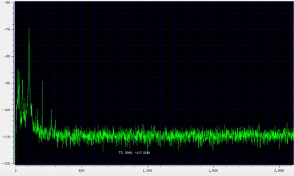
Fig. 7The test diagram of signal processing synchronization
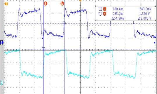
a) AD2 of board 1 versus AD1 delay of board 1
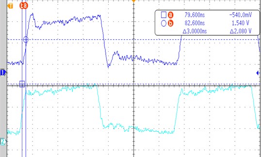
b) AD1 of board 2 versus AD1 delay of board 1
Table 1The synchronous signal test data record table
Card serial number | AD synchronous signal error (unit: ns) | |||||||
AD1 | AD2 | AD3 | AD4 | AD5 | AD6 | AD7 | AD8 | |
Card 1 | (Ref AD) | 54.8 | 52.4 | 53.6 | 53.2 | 3.6 | 68.4 | 51.6 |
Card 2 | 3.0 | 52.2 | 53.4 | 67.4 | 52.8 | 5.0 | 118.4 | 53.2 |
Card 3 | 17.2 | 17.0 | 24.8 | 22.8 | 23.6 | 53.2 | 16.6 | 15.8 |
Card 4 | 69.6 | 4.8 | 68.8 | 69.2 | 54.0 | 54.0 | 55.2 | 54.0 |
Card 5 | 6.0 | 17.6 | 69.0 | 52.4 | 97.6 | 15.6 | 69.4 | 99.0 |
Card 6 | 16.8 | 17.2 | 15.6 | 53.2 | 53.2 | 53.2 | 54.8 | 54.4 |
Card 7 | 52.8 | 52.8 | 4.0 | 54.8 | 52.8 | 23.6 | 53.6 | 25.2 |
Card 8 | 23.6 | 16.0 | 52.8 | 54.8 | 51.6 | 54.0 | 2.4 | 54.4 |
The measurement results of synchronous clock comparison show that the delay between each acquisition channel is less than 100 ns (less than the millisecond level index requirements), and the signal processing synchronization is good, which meets the requirements of signal synchronization processing of fiber optic hydrophone array.
6. Conclusions
In the measurement of underwater structure radiated noise, optical power fluctuation and system demodulation failure are caused by factors such as light source wavelength drift and array deformation, which affect the measurement effect of noise measurement system. An adaptive gain control system of photoelectric preamplifier based on digital AGC is designed to improve the demodulation of optical fiber source and multi-channel optical telecommunication The experimental results show that the designed adaptive control system can achieve stable output wavelength of fiber-optic hydrophone array, excellent frequency response characteristics, good signal processing synchronization between acquisition channels, which can meet the design requirements of underwater equipment radiated noise measurement system, and provide reliable support for improving the accuracy of underwater structure radiated noise measurement.
References
-
Wang Youzhao, Huang Jing Optical Fiber Sensing Technology. Xi’an University of Electronic Science and Technology Press, Xi’an, 2012, p. 84-108.
-
Cai Bingtao, Chen Xiaobao Design and implementation of fiber optic hydrophone array demodulation system based on FPGA. Optical Fiber and Cable and Its Application Technology, Vol. 1, Issue 33, 2018, p. 36-40.
-
Li Jianqiang, Qi Hongyu Analysis of feedback automatic gain control circuit. Electromagnetic Field and Microwave, Vol. 48, Issue 12, 2018, p. 1096-1099.
-
Liu Yaru Research and Design of Automatic Gain Control Circuit for Wireless Communication Applications. Hangzhou University of Electronic Science and Technology, Hangzhou, 2017.
-
Chen Dong, He Lin, Chen Shuchun, et al. Design of a weak photoelectric signal modulation and demodulation circuit. Electronic Measurement Technology, Vol. 39, Issue 4, 2016, p. 119-122132.
-
Yu Xiaozhi Study on Interferometric Optical Fiber Acoustic Sensor System and AGC Scheme. Harbin Engineering University, Harbin, 2007.
-
Sui Zhanju, Lu Wen Design and implementation of an improved AGC. Radio Engineering, Vol. 40, Issue 12, 2010, p. 61-64.
-
Li Pengchong Research and System Implementation of Multi-Channel PGC Demodulation Technology Based on FPGA. Harbin Engineering University, Harbin, 2015.
-
Xing Guanghui, Zhang Wanrong, Xie Hongzhi, et al. An ultra wideband variable gain amplifier using attenuator. Microelectronics, Vol. 43, Issue 4, 2013, p. 468-470.
-
Su Ming Development of Wide Range AGC Control Circuit for HF Receiver Front End. Wuhan University of Technology, Wuhan, 2012.
About this article

