Abstract
Linear models of rubber torsional vibration dampers do not consider the non-linear properties of rubber, and most of those, which take this feature into account, are troublesome or even impossible to use in the design and optimization process. In this paper the authors propose a nonlinear model of damper, which can assist engineers in designing.
1. Introduction
The reciprocating internal combustion engine’s crankshaft rotation is a result of the tangential force acting on a crank, which direction does not coincide with the axis of the connecting rod. It is one of the components of the sum of the forces of inertia derived from the masses in forth – turning motion and gas pressure forces. The tangential force changes with a change of crank angle, causing the occurrence of the shaft’s positive and negative accelerations. They result in torsional vibrations of the shaft [1]. Until recent years, this issue was especially dangerous only in in-line, six or more cylinder engines. Crankshafts in such engines are long, and consequently, their torsional stiffness is relatively low. Therefore there is a danger that in the range of engine operating speed the resonance phenomena may occur and the amplitude of the crankshaft’s torsional vibrations will exceed the limit values, which could drive to fatigue failures of the crankshaft and high bearing wear as well as other side effects on things driven by the crankshaft.
In recently constructed internal combustion engines of cars the increase of such parameters as power, torque, the level of compression in the cylinders, rotational speed, etc., and in the same time the reduce of their weight and size caused that the danger of the work of crankshafts in the area of resonance began to be issue in this group also. Engine designers were faced with the necessity of careful analysis of crankshaft torsional vibrations and in justified cases to take efforts for their minimization. There are two main ways to avoid crankshaft to be working in the field of resonance:
• “shift” natural frequency of the crankshaft beyond the working engine speed;
• minimize the amplitude of the torsional vibration of resonance through the use of various types of dampers.
The first method requires increasing crankshaft torsional stiffness while reducing mass and moments of inertia of pistons and connecting rods, which in most cases is practically impossible to implement from a technical point of view. Therefore, the second way – the use of various types of torsional vibration dampers – is increasingly and widely used [2]. In passenger car engines most commonly are used rubber torsional vibration dampers, which are mounted on so-called “free” end of the crankshaft (the end opposite to the flywheel). These dampers are relatively light, inexpensive in production and require no maintenance during operation. In addition, very often they perform the function of the pulley.
Rubber torsional vibration dampers are designed or chosen for the specific type of engine. It is necessary in this case to analyze the torsional vibrations of crankshaft without a damper. The results of the analysis allow the determination of the amplitude of the resonance of the shaft, and above all, the determination of its natural frequency of torsional vibrations. The values of the resonant frequencies of the shaft are considered at the design stage of the damper as excitation frequency. At this stage, very helpful to designers turns out to have a model of the damper, which allows optimal adjustment of its parameters for the specific engine type.
2. Model of rubber torsional vibration damper
Typical rubber torsional vibration damper consists of the inertia ring connected to the hub with the ring of rubber of suitable dynamic stiffness and damping factor (Fig. 1). This is an example of the damper, which is “tuned” (designed) for the most dangerous resonant frequency of the crankshaft torsional vibrations for which they have the highest amplitude [3]. In fact, it is a dynamic vibration eliminator, which minimizes the crankshaft’s torsional vibrations by own inertia force. It adds into the system an additional degree of freedom. The effect of this is splitting the original resonance peak into two “new” resonance peaks. In addition, vibration energy is dissipated through the phenomenon of internal friction in the rubber element connecting the hub with inertia ring. The damper is mounted at the free end of the crankshaft, and usually also functions as a pulley (Fig. 1). By contractual optimum torsional vibration damper is understood the one that minimizes the level of maximum tangential stress fatigue in the whole range of engine operating speed [4].
Fig. 1Construction of rubber torsional vibration damper and common way of its mounting
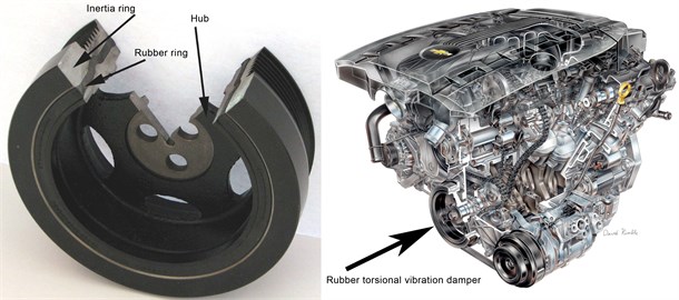
Fig. 2Schema of torsional vibration damper model
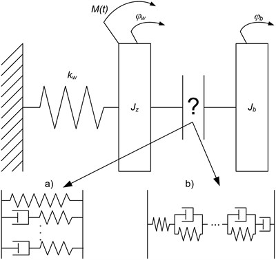
From the point of view of the designer of torsional vibration damper its model should allow for relatively easy selection of such parameters of the damper as: mass moments of inertia of the hub, and in particular of the inertia ring and the selection of the optimum physical properties of the rubber, of which is made a flexible element connecting the hub with the inertia ring. Taking into account these considerations torsional vibration damper can be modeled quite intuitively as shown schematically in the figure (Fig. 2).
Thus, arises at this point the question how to describe the rubber ring connecting the hub with the inertia ring. In the rubber we are dealing phenomena such as stress relaxation and creep (increase of deformation caused by constant stress) [5].
The phenomenon of stress relaxation can be described mathematically using the Maxwell model [6], which is a serial combination of one spring and one viscous damper. However, it requires complexity to increase its adaptation to reality. For this purpose, it is combined in parallel with an additional spring. However, when such a model representation of the phenomenon of relaxation is still not sufficient, there is a need to introduce new elements composed of single Maxwell models (Fig. 2(a)).
Creep can be described mathematically by use of the Kelvin-Voigt model [6], which is a parallel combination of one spring with one viscous damper. Naturally, two-piece Kelvin-Voigt model is too simple to describe non-linear material, such as rubber. Therefore, as in the Maxwell model, to a simple Kelvin-Voigt model there is a need to add more components to obtain a satisfactory accuracy of the calibration (Fig. 2(b)).
As can be seen, the use of any of the described methods in the torsional vibration damper’s model in practice rule out the possibility of its use in the design process - its identification requires each time changes in the structure of the model. Definitely better solution would be to have a model with a strictly defined structure, sensitive only to change of parameters, and an additional advantage would be if these parameters could be linked to physical quantities.
In torsional vibration damper rubber ring is subjected to rapidly changing loads. As discussed in works [5-8], in such cases the rubber physical properties change. From the point of view of the damper’s designer most important are changes in mechanical properties such as stiffness and damping. These properties are affected i.a. by following parameters:
• amplitude of excitation,
• frequency of excitation,
• temperature,
• aging of the rubber.
The less parameters needed to identify the model, the more it is useful in the process of designing. Assuming that the time after which the structure of the rubber undergoes a process of aging is much greater than the “dynamic” time we can roughly assume that stiffness and damping will not have been changing during exploitation time of damper. Temperature changes occur in shorter time, but the variation in the stiffness and damping of rubber caused by this factor continues only until it reaches the so-called rubber saturation temperature. And under these circumstances, during most of their operating time, rubber torsional vibration dampers are working – thus, we can assume that the stiffness and the damping are stationery in the model.
Fig. 3Schema of proposed nonlinear model of torsional vibration damper
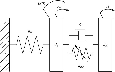
Taking these assumptions into consideration we can propose the following model of rubber torsional vibration damper (Fig. 3).
The parameters needed to identify the proposed model are:
• replacement moment of inertia of the shaft with the damper’s hub,
• replacement stiffness of the shaft,
identified during the analysis of torsional vibration of the engine, for which the torsional vibration damper is being designing, and:
• moment of inertia of the inertia ring,
• stiffness of the rubber ring,
• damping the rubber ring.
Adjusting these parameters should allow for the selection of the optimal torsional vibration damper for the specific type of engine.
Fig. 4Exemplary variation in stiffness of rubber with amplitude of oscillations
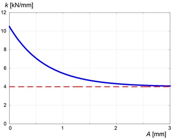
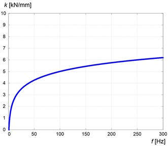
Fig. 5Exemplary variation in stiffness of rubber with frequency of oscillations
On the stiffness of the rubber ring affect both the amplitude and frequency of excitation. These relationships are nonlinear. And with such changing excitations we are dealing in the case of torsional vibrations dampers used in car engines.
As discussed in works [5-8], the stiffness of the rubber is higher the lower the amplitude of the vibration is. In this case, starting from the upper limit (for very low amplitude) value of the Young modulus approaches the predetermined lower limit corresponding to the vibration of high amplitude (Fig. 4).
Also as discussed in these works [5-8] the rubber stiffness increases with increasing of the oscillation frequency (Fig. 5).
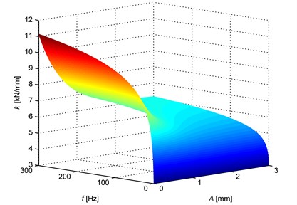
In the range of frequencies being interesting for the designer of rubber vibration damper these relationships can be presented on the collective chart (Fig. 6).
Fig. 6Exemplary variation in stiffness of rubber with amplitude and frequency of oscillations
Sum up the considerations, the following mathematical model of rubber vibration damper can be proposed:
where: – dynamic stiffness coefficient of the rubber ring, – static stiffness coefficient of the rubber ring, – damping coefficient of the rubber ring, – moment of inertia of the inertia ring, – replacement moment of inertia of the shaft with the damper’s hub, – replacement stiffness of the shaft, – angle of rotation of the shaft, – angle of rotation of the inertia ring, , , – coefficient of amplitude of oscillations influence, – coefficient of frequency of oscillations influence.
3. Conclusion
In the proposed non-linear model of the rubber torsional vibration damper parameters and are set on the basis of the preliminary analysis of the torsional vibrations of the crankshaft of the engine, for which the damper is being designed. Values , , are functions of geometrical parameters of the damper and physical properties of viscoelastic element (the rubber ring). Operation on them allows finding the optimal damper for the specific type of engine. The moment of inertia of the damper’s hub can be determined simultaneously with the design of its shape, e.g. in CAD software. The static coefficient of rubber stiffness and the damping factor are characteristic for the material of which the rubber ring is going to be made of, and their values can be obtained from the tables provided by rubber manufacturers on the basis of the Shore A hardness. Although the value of the damping coefficient of viscoelastic materials depends on the frequency of excitation, in the range of operating frequencies of torsional vibration damper changes are small enough that relatively with high accuracy can be treated in this case as a stationary viscous damping. The coefficients of amplitude and frequency of oscillations influence , , and the value of dynamic stiffness coefficient can be determined experimentally. Numerous works conducted by the authors [9-12] proved good agreement of the results of the proposed model with the experimental studies.
References
-
Jędrzejowski J. Mechanics of Crank Systems of Automobile Engines. WKiŁ, Warszawa, 1986, (in Polish).
-
Sisco W. C. Cranckshaft Torsion and Dampers. www.BHJDynamics.com.
-
Aubert A., Howle A. Design Issues in the Use of Elastomers in Automotive Tuned Mass Dampers. SAE Technical Paper 2007-01-2198, 2007.
-
Homik W. Broadband Torsional Vibration Dampers. ITE Radom, 2012, (in Polish).
-
Radkowski S., Pękalak M. Rubber Viscoelastic Elements. PWN Warszawa, 1989, (in Polish).
-
Honda Y., Saito T., Wakabayashi K., Kodama T., et al. A Simulation Method for Crankshaft Torsional Vibration by Considering Dynamic Characteristics of Rubber Dampers. SAE Technical Paper 891172, 1989.
-
Sjoberg M. On Dynamic Properties of Rubber Isolators. Doctoral Thesis, KTH, Royal Institute of Technology, Department of Vehicle Engineering, Stockholm, 2002.
-
Martini E., Tonoli A., Amati N., Guala A. Dynamic Characterization of Viscoelastic Materials. SAE Technical Paper 2004-01-3304, 2004.
-
Pankiewicz J., Deuszkiewicz P., Dziurdź J., Zawisza M. Modeling of powertrain system dynamic behavior with torsional vibration damper. Advanced Materials Research, Vol. 1036, 2014, p. 586-591.
-
Pankiewicz J., Zawisza M. Research of torsional vibration of the internal combustion engine’s crankshaft with various dampers (TVD). Vibroengineering Procedia, Vol. 3, 2014, p. 229-232.
-
Pankiewicz J., Dziurdź J. Examinations of torsional vibration dampers used in internal combustion engines. Proceedings of 17th Ogólnopolskie Sympozjum Diagnostyka Maszyn, Politechnika Śląska, Wisła, 2010, (in Polish).
-
Pankiewicz J., Homik W. Examinations of torsional vibration dampers used in reciprocating internal combustion engines. Polish Journal of Environmental Studies, Vol. 20, Issue 5A, 2011, p. 108-111.
About this article

