Abstract
An impact base excitation method with stacked PZT actuator for MEMS dynamic characterization was studied. A typical impact base excitation device mainly includes a stacked PZT actuator, a base structure and an impulse power source. The principle of this method is as follows. The tested microstructure was attached on the top surface of PZT through the base structure in between. Applying a transient impulse voltage on PZT, an impact will be generated in the vertical direction of PZT. The impact will strike the base structure to vibrate. The tested microstructure can be excited by the movement of the base structure. Basing on the principle of this method, a dynamic measurement system for piezoresistive microcantilevers was established. A laser deflection system was developed to measure the frequency bandwidth of excitation device. The experiments on the frequency bandwidth of excitation device and the dynamic characteristics of a T-shaped piezoresistive microcantilever were carried out. The results show that this method is effective for MEMS dynamic characteristics measurement.
1. Introduction
The dynamic measurement techniques for MEMS microstructures have attracted a lot of attention in recent years. The micromachined devices which have the features of small size, light weight and low power consumption were successfully applied in both civilian areas and military areas, such as smart weapons, fuse of missile, automobile, ink jet printers and cell phone, etc. [1-5]. For most of MEMS devices, their performance is closely related to the dynamic characteristics of internal moveable microstructures. Therefore, to guide the designing, simulation and manufacturing of MEMS devices, it is very important to study the dynamic characteristics of microstructures and corresponding measurement techniques.
There are two aspects to be considered for MEMS dynamic measurement techniques, the vibration measurement techniques and the excitation methods. Due to the small size and high resonant frequency of microstructure, the conventional modal testing techniques cannot be employed without modification. For the last three decades, many vibration measurement techniques and excitation methods were proposed, and successfully used in MEMS dynamic characterization.
Laser Doppler Vibrometry technique, the famous non-contact measurement method for large conventional structures, has been wildly used in the vibration measurement of microstructures [6]. This method is very effective in both out-of-plane and in-plane vibration measurement. Stroboscopic Phase-shifting Interferometer technique is another valuable method [7]. In this method, the vibration response of the microstructure was obtained by recording the interferograms on the vibrating microstructure with the aid of stroboscopic illumination. Computer-Micro-Vision technique is a non-interferometry-based method [8]. By capturing the periodic motion image of the microstructure and then processing the obtained signal with digital-image-processing algorithms, the vibration responses of microstructures can be obtained. Photomicrography is a unique method for dynamic characterization of microstructures with periodic behaviors [9]. In this method, the microstructure was driven by sweeping driving signal. The resonance frequencies of microstructure can be obtained while the maximum displacement was observed. Electronic Speckle Pattern Interferometry, the video holography technique, was also used to measure the vibration responses of microstructures [10]. This method has shown great potential in the measurement of both out-of-plane and in-plane vibrations of microstructures. Besides these non-contact optical techniques, the methods with embedded sensing elements, such as piezoresistive elements [11], piezoelectric elements [12] and capacitive elements [13], were also employed in the vibration measurement of microstructures. Compared with the non-contact optical methods, the methods with embedded sensing elements have the lower cost, and are suitable for in-situ MEMS dynamic measurement.
As to the excitation methods, there are electrostatic excitation method [14], piezoelectric excitation method [15], thermal excitation method [16], magnetic excitation method [17], acoustic excitation method [18], laser excitation method [19], and base excitation method with PZT [20, 21]. These excitation methods can be divided into three categories: the contact excitation method, the non-contact excitation method and the half-non-contact excitation method. The contact excitation method includes the electrostatic excitation method, piezoelectric excitation method, thermal excitation method and magnetic excitation method. These methods need the extra actuating elements to be fabricated in the microstructure. Thus the dynamic characteristics of the microstructure will be changed. The non-contact excitation method includes the laser excitation method and the acoustic excitation method. These two methods have the advantage over the contact excitation method because no additional actuating elements are needed. However, their excitation band widths are not enough for the microstructures with high natural frequencies. The base excitation method with PZT is so-called half-non-contact excitation method. In this method, the microstructure is mounted on the top surface of PZT through a base structure. Applying alternating voltage signals on the two electrodes of PZT, the PZT will vibrate due to the inverse piezoelectric effect. Then the microstructure can be excited by the movement of PZT. Usually, the PZT was driven by a sweeping frequency signal. The resonant frequencies of microstructure can be obtained when the max amplitude occurred. Compared with the other excitation methods, this method is non-destructive and simple. However, this method is limited by the low Curie temperature of piezoelectric materials, because there will be a rapid temperature rise inside the piezoelectric ceramic while the PZT was operating on a high resonance frequency.
In this paper, an impact base excitation method with stacked PZT actuator was studied. In this method, the PZT driven by a transient impulse signal was used to impact the testing microstructure. The vibration signal of the microstructure was obtained by piezoresistive icrocantilevers. The excitation bandwidth of this method was tested by the laser deflection method. A dynamic measurement system for microstructures was developed. The dynamic characteristics of piezoresistive microcantilevers were tested and discussed.
2. Principle of impact base excitation method with PZT
The impact excitation is an effective method in conventional modal measurement. In this method, a force hammer is used to generate an impact to strike the tested structure. The impact with a specific amplitude and duration can excite all the interested frequencies of the tested structure within a certain frequency range. However, due to the size mismatch and low excitation bandwidth, this method cannot be used in MEMS dynamic measurement. To solve these two problems, an impact base excitation method with stacked PZT actuator was considered.
The base excitation method was used to solve the size mismatch problem. The base structure has two functions. One is as a supporting structure to install the tested microstructure. The other is transmitting impact energy from the excitation source to the tested microstructure. Thus, the impact is not applied on the microstructure, but the base structure.
To solve the second problem, the stacked PZT actuator was used as the excitation source, which was excited by a transient impulse signal, not the sweeping frequency signal. PZT can be used as the impact excitation source because of its quick response property. Applying a transient impulse signal on a bulk PZT, due to the inverse piezoelectric effect, an impact is obtained in the vertical direction of PZT. The duration time of the impact is closely related to the deformation rate . According to the piezoelectric displacement equation [22], can be determined by Eq. (1):
where, is the number of layers, is the equivalent capacitance, is the piezoelectric constant and is the charging current. It can be seen that the deformation rate is determined by two factors, one is the characteristics of PZT, and the other one is the output performance of charging power. So to obtain the shorter duration time of impact, both a bulk stack PZT with small equivalent capacitance and a charging power with high voltage rise rate are needed.
The principle of impact base excitation method with stacked PZT actuator is as follows. The tested microstructure is installed on the top surface of a stacked PZT actuator through a base structure in between. The bottom surface of the PZT is fixed on an isolating platform. Applying a transient impulse signal on the PZT, an impact can be generated in the vertical direction of PZT. The base structure starts to vibrate due to the effect of the impact. Then the microstructure can be excited by the movement of the base structure.
3. Experiments setups
A dynamic measurement system was established for dynamic characterization of microstructures. In the system, an impact excitation device with stacked PZT actuator was developed to excite the tested microcantilevers. The method with embedded piezoresistive elements was employed to obtain the output response of microstructures. To figure out the excitation bandwidth of the stacked PZT actuator, the laser deflection method was used to detect the vibration response of the PZT.
3.1. Base excitation device
A base excitation device was developed basing on the principle of the impact base excitation method with stacked PZT actuator. Its schematic diagram was shown in Fig. 1. A stacked bulk PZT actuator, PTBS200, was used to excite the microstructures. The dimension of PZT’s crossing section is 8×8 mm2, and the height is 10 mm. The equivalent capacitance of the PZT is 0.9 μF. Its maximum output force is about 1000 N if applying 200 V voltage on PZT suddenly. The first order modal frequency of the PZT is 16.4 KHz. A circle steel plate was chosen as the base structure. Its diameter is 10 mm, and the thickness is 2 mm.
Fig. 1A schematic diagram of impact base excitation method with PZT
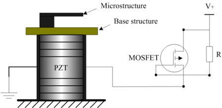
An impulse power source for PZT was developed. Its max output voltage is 200 V. To obtain the enough voltage rise rate, IRF9640 MOSFET transistor was chosen as the switch. Its turn-on time is less than 60 ns.
3.2. Piezoresistive microcantilever unit
The method with embedded piezoresistive elements was used to detect the vibration response of microstructures. The principle of this method is as follows. If a piezoresitive microcantilever vibrates, an alternating stress will be applied on the piezoresitive elements, thereby causing a change in resistance which can be measured by a full bridge. Thus, the vibration response of microcantilever can be detected by measuring the output voltage of the full bridge. Basing on the principle of this method, a T-shaped piezoresitive microcantilever was fabricated, as was shown in Fig. 2.
Fig. 2SEM photo of T-shaped piezoresistive microcantilever
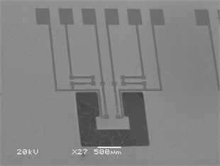
The beam part of microcantilever is 800 μm long and 600 μm wide. The mass part of microcantilever is 400 μm long and 800 μm wide. The thickness of micocantilever is 10 μm. Six piezoresitive elements were fabricated on the top surface of the microcantilever. Two of them were along with the [110] direction, and the other four were along with the [100] direction. The first order natural frequency of the piezoresistive microcantilever was simulated by ANSYS. The value is 8.65 kHz. The fabricated silicon wafer was separated into individual chips. The fabricated piezoresistive microcantilever chip was bonded onto a chip carrier which was suitable for wiring. The obtained output signal of the bridge, amplified 100-fold by an AD524 differential amplifier, was read through a PCI-1714 data acquisition card of Advantech Corporation using LabView.
3.3. Laser deflection system
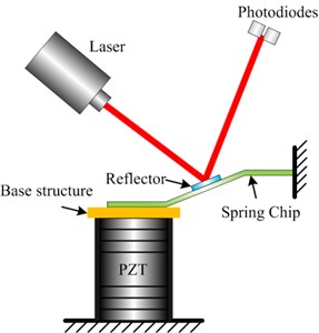
A laser deflection system was established to measure the dynamic responses of PZT, as was shown in Fig. 3. The principle of laser deflection method is as follows. A laser projected onto the surface of the tested object. Its reflected laser was captured by two silicon photo diodes. As soon as the tested object vibrated, the reflected laser spot moved between the two silicon photo diodes. The vibration response of the tested object can be obtained by recording the change of light intensity of two silicon photo diodes.
There are two problems to be solved if applying this method on PZT. Firstly, the intensity of reflected laser is not enough due to the rough surface of PZT. Secondly, the moving distance of the laser spot on the silicon photo diodes is too small to be distinguished. To solve these two problems, a spring chip and a reflector were used, as was shown in Fig. 4. The one side of the spring chip was fixed on a large rigid platform, and the other side was placed on the top surface of PZT. The glass reflector was attached to the spring chip. The rotating angle of the reflected laser beam can meet the requirement of detection by adjusting the position of spring chip. Thus, the reflected laser can be more easily detected by the photo diodes.
Due to the high natural frequency of PZT, the silicon photo diodes must have the features of quick response. Also the operational amplifiers were required a large bandwidth. The S4797-01 silicon photo diode and AD524 operational amplifier were selected. The response time of S4797-01 silicon photo diodes is less than 0.2 μs. The bandwidth of AD524 operational amplifier is 25 MHz. The light intensity signals were detected by S4797-01 silicon photo diodes, and converted to two voltage signals as the input signals of AD524 operational amplifier. The output signal of the AD524 was read through a PCI-1714 data acquisition card of Advantech Corporation using LabView.
Fig. 3Laser deflection system
Fig. 4A schematic diagram of laser deflection method for PZT vibration detection
4. Results and discussion
4.1. Bandwidth of excitation device
To obtain the frequency bandwidth of excitation device, the vibration response of PTBS200 stacked PZT actuator driven by 200 V impulse voltage signal was measured by the laser deflection system, as was shown in Fig. 5. The response time of the PZT is about 6.1μs. The response time of the PZT is much larger than the response time of photo diode, which means the S4797-01 silicon photo diode is suitable for the laser deflection system. According to the principle of impact excitation method [23], the excitation bandwidth of stacked PZT actuator can be estimated by the Eq. (2) and Eq. (3):
where, is the excitation bandwidth of stacked PZT actuator, is the response time of PZT, is the time that the PZT reached the equilibrium position for the first time, is the time that the PZT reached the peak for the first time. So the excitation bandwidth of PZT can be calculated as about 82 kHz. It can be seen that the first order modal frequency of the PZT is far less than its bandwidth. The better excitation capability can be obtained when the PZT is driven by transient impulse signal, instead of sweeping frequency signal.
Fig. 5Response of PZT driven by 200 V impulse voltage
4.2. Dynamic characteristics of piezoresistive microcantilever
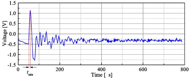
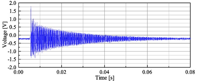
The dynamic characteristics of piezoresistance microcantilever were measured by the developed testing system. The obtained vibration signal was shown in Fig. 6. It can be seen that at the beginning of the response signal, those cycles cannot represent the free vibration of microcantilever because they contain the responses of both the microcantilever and the base structure. After that, a typical damped free vibration of the microcantilever can be obtained.
Fig. 6Vibration Response signal of T-shaped piezoresistive microcantilever
To obtain the first-order undamped natural frequency of the microcantilever, the microcantilever was considered as a single-degree-of-freedom vibration system. Basing on the principle of mechanical vibrations, the fundamental undamped natural frequency of the microcantilever can be calculated by the Eq. (4) [23]:
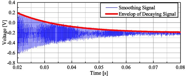
where is the first-order undamped natural frequency, is the first-order damped natural frequency and is the damping ratio. Performing FFT on the obtained signal, the first-order damped natural frequency can be obtained, as was shown in Fig. 7. The obtained first-order damped frequency of T-shaped piezoresistive micro-cantilever is 8.959 kHz. To obtain the undamped natural frequency, the damping ratio needs to be calculated. The damping ratio cannot be directly obtained by the envelope of the obtained decaying signal because this signal contained both the response the PZT and the response of the microcantilever. After the PZT stopped vibration, the free damping vibration of the microcantilever can be obtained. So the time domain signals ranging from 0.02 to 0.08 s were selected as the free damped vibration signal of the tested microcantilever. The selected signals were smoothed with a Savitzky-Golay filter to reduce the noise. As was shown in Fig. 8, the envelope of the decaying signal can be obtained by the smoothed signal. Basing on the classical theory of free damping vibration, the damping ratio can be calculated by the envelope of the decaying signal. The damping ratio of T-shaped piezoresistive microcantilever is 0.0056. According to the Eq. (4), the first-order undamped natural frequency of T-shaped piezoresistive microcantilever was calculated as 8959.1 Hz. It can be seen that due to the very small damping ratio, the first-order undamped natural frequency of microcantilever is almost equal to its first-order damped frequency.
There is a small difference between the experiment result and the FEA value. This difference may be explained by the following reasons. Firstly, the inaccuracy of measuring the thicknesses of microcantilever will affect the FEA value. Secondly, the fabrication process of silicon microcantilever affects the material properties, such as density and elastic modulus. Finally, the non-ideal boundary condition of the etched microcantilever also has influence on the FEA value.
Fig. 7Frequency spectrogram of T-shaped piezoresistive microcantilever
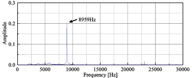
Fig. 8Envelope of the decaying signal of T-shaped piezoresistive microcantilever
5. Conclusions
The impact base excitation method with stacked PZT actuator was studied. In this method, the stacked PZT driven by transient impulse voltage was used to generate the impact. The base structure was struck to vibrate. The tested microstructure can be excited by the movement of the base structure. Basing on this method, a dynamic measurement system was developed. The dynamic characteristics of the T-shaped piezoresistive microcantilever were tested by the developed measurement system. The results show that the impact base excitation method with stacked PZT actuator is an effective method for the excitation of microstructures. This method has two advantages over the base excitation method with PZT driven by a sweeping frequency signal. Firstly, there is no obvious temperature rise inside PZT because the duration time of driving signal for PZT is very short. Secondly, this method is more suitable to excite the microstructures with high natural frequencies because of its high excitation bandwidth.
References
-
Van Beek J. T. M., Puers R. A review of MEMS oscillators for frequency reference and timing applications. Journal of Micromechanics and Microengineering, Vol. 22, Issue 1, 2012, p. 013001.
-
Bogue R. Recent developments in MEMS sensors: a review of applications, markets and technologies. Sensor Review, Vol. 33, Issue 4, 2013, p. 300-304.
-
Voiculescu I., Nordin A. N. Acoustic wave based MEMS devices for biosensing applications. Biosensors and Bioelectronics, Vol. 33, Issue 1, 2012, p. 1-9.
-
Guo Z. S., Cheng F. C., Li B. Y., Cao L., Lu C., Song K. Research development of silicon MEMS gyroscopes: a review. Microsystem Technologies, Vol. 21, Issue 10, 2015, p. 2053-2066.
-
Michael K., White N. MEMS for Automotive and Aerospace Applications. First Edition, Elsevier, Netherlands, 2013.
-
Sharma A., Mukhiya R., Kumar S. S., Gopal R., Pant B. D. Dynamic characterization of bulk micromachined accelerometer using laser Doppler vibrometer (LDV). Microsystem Technologies, Vol. 21, Issue 10, 2015, p. 2221-2232.
-
Shavrin I., Lipiäinen L., Kokkonen K., Novotny S., Kaivola M., Ludvigsen H. Stroboscopic white-light interferometry of vibrating microstructures. Optics Express, Vol. 21, Issue 14, 2013, p. 16901-16907.
-
Lu Q. H., Zhang X. M., Fan Y. B. Robust multiscale method for in-plane micro-motion measurement based on computer micro-vision. Chinese Journal of Mechanical Engineering, Vol. 45, Issue 2, 2009, p. 164-169.
-
Rembe C., Tibken B., Hofer E. P. Analysis of the dynamics in microactuators using high-speed cine photomicrography. Journal of Microelectromechanical Systems, Vol. 10, Issue 1, 2001, p. 137-145.
-
Flynn E., Bassman L., Smith T., Lalji Z., Fullerton L., Leung T., Koskelo A. Three-wavelength electronic speckle pattern interferometry with the Fourier-transform method for simultaneous measurement of microstructure-scale deformations in three dimensions. Applied Optics, Vol. 45, Issue 14, 2006, p. 3218-3225.
-
Partridge A., Reynolds J., Chui B., Chow E., Fitzgerald A., Zhang L., Kenny T. A high-performance planar piezoresistive accelerometer. Journal of Microelectromechanical System, Vol. 9, Issue 1, 2000, p. 58-66.
-
Kon S., Oldham K., Horowitz R. Piezoresistive and piezoelectric MEMS strain sensors for vibration detection. The 14th International Symposium on Smart Structures and Materials and Nondestructive Evaluation and Health Monitoring, International Society for Optics and Photonics, 2007, p. 65292V.
-
Xiong X., Wu Y. L. D., Jone W. B. A dual-mode built-in self-test technique for capacitive MEMS devices. IEEE Transactions on Instrumentation and Measurement, Vol. 54, Issue 5, 2005, p. 1739-1750.
-
Liu C., Yue S., Xu Y. Nonlinear resonances of electrostatically actuated nano-beam. Journal of Vibroengineering, Vol. 16, Issue 5, 2014, p. 2484-2493.
-
Littrell R., Grosh K. Modeling and characterization of cantilever-based MEMS piezoelectric sensors and actuators. Journal of Microelectromechanical Systems, Vol. 21, Issue 2, 2012, p. 406-413.
-
Shi H. C., Fan S. C., Zhang Y. W., Sun J. H. Nonlinear dynamics study based on uncertainty analysis in electro-thermal excited MEMS resonant sensor. Sensors and Actuators A: Physical, Vol. 232, Issue 1, 2015, p. 103-114.
-
Wilson C. J., Bogy D. B. An experimental modal analysis technique for miniature structures. Journal of Vibration and Acoustics, Vol. 118, Issue 1, 1996, p. 1-9.
-
Ricci J., Cetinkaya C. Air-coupled acoustic method for testing and evaluation of microscale structures. Review of Scientific Instruments, Vol. 78, Issue 5, 2007, p. 005105.
-
Xiong L., Zhou Q., Wu Y., Chen P. New laser excitation method for modal analysis of microstructure. Mechanical Systems and Signal Processing, Vols. 50-51, 2015, p. 227-234.
-
Burdess J., Harris A., Wood D., Pitcher R., Glennie D. A system for the dynamic characterization of microstructures. Journal of Microelectromechanical Systems, Vol. 6, Issue 4, 1997, p. 322-328.
-
Ozdoganlar O., Hansche B., Carne T. Experimental modal analysis for microelectromechanical systems. Experimental Mechanics, Vol. 45, Issue 6, 2005, p. 498-506.
-
Jaffe B., Cook W. R., Jaffe H. Piezoelectric Ceramics. First Edition, Academic Press, London and New York, 1971.
-
Pilkey W. D. Formulas for Stress, Strain, and Structural Matrices. First Edition, Wiley, New York, 1993.
About this article

This work was supported by the National Natural Science Foundation of China (Grant No. 51305191) and the General Project of Liaoning Provincial Education Department of China (Grant No. L2015009).
