Abstract
This paper presents a rational approximation method for fractional calculus operators in the given frequency range and the error, which is based on the best rational approximation definition. The fractional integral operator is selected as an example to describe the construction of the rational approximation functions. An application case () is used to illustrate the effectiveness of the proposed method. The obtained approximation function in the frequency domain is a best rational approximation function, which can further improve the accuracy of the approximation without increasing the orders. On the basis of the presented rational approximation method, a rational approximation equation of a fractional-order PID controller is obtained. Finally, the method for analyzing the optimization and frequency characteristics of the fractional-order controller is implemented to demonstrate the good frequency characteristic and best structure. The results from theoretical analysis and experimental verification show that the proposed method provides a new design idea for the effective application of the fractional-order PID controller in engineering.
1. Introduction
In recent years, fractional-order systems and controllers have attracted much attention [1]. Fractional-order systems, as a generalization of classical integer-order systems, can be defined by the mentioned integral and derivative operators [2-5]. Compared with integer-order systems, fractional-order systems can better describe the dynamics of real systems, such as electrode-electrolyte polarization, electromagnetic waves, diffusion equations and so on [6-15]. Because the conventional proportion-integral-derivative(PID) controller is the most widely used control type in industry, the fractional-order PID controller has been considerably researched [16, 17]. The fractional-order PID controllers, as a generalization of traditional integer-order PID controllers, are used to enhance the performance of control systems.
The differential equation of a fractional-order PID controller is described as:
where , and represent the proportion, integral, and derivative respectively.
The Eq. (1) is taken the Laplace transform, and zero initial conditions are assumed, thus the following equation is obtained:
where is the variable of Laplace. When is 1 and is 1, the PID is a particular case.
As is known, when the integer-order systems have a limited memory, the fractional-order systems have an unlimited memory. There mainly has the frequency domain based on the Riemann-Liouville definition and Grunwald-Letnikov definition and the time domain based on Caputo definition. Tseng [18] investigated the design of a fractional-order FIR differentiator. Chen et al. [19] presented a direct recursive discretization of the Tustin operator and direct discretization method by using the Al-Alaoui operator. Chen and Vinagre [20] presented a new infinite impulse response type digital fractional-order differentiator by using a new family of first-order digital differentiators. Podlubny et al. [21] proposed several possible analog methods for obtaining suitable rational approximations. Krishan [22] reviewed the analysis, design and applications of analog and digital differentiators and integrators of fractional-order and proposed time and frequency domain analysis method to realize a fractance device. Oustaloup et al. [23] conducted the synthesis of differentiators with integer, non-integer, real or complex orders, and the action is limited to any given frequency bandwidth. Charef [24] presented an analogue realization of fractional-order integrator, differentiator and fractional PID controllers. Romero et al. [25] discussed the use of Chebyshev polynomial theory to achieve accurate discrete-time approximations to the fractional-order differentiator/integrator in terms of IIR filters. Mekhnache [26] presented a method for designing fullband and non-fullband IIR digital integrators with linear phase to approximate fractional-order integrators with IIR filters. Tseng [27] presented the design problems of the digital Feller fractional-order integrator. Benkhettou et al. [28] introduced a general notion of fractional derivative to define functions on arbitrary time scales and develop the basic tools for time-scale fractional calculus.
However, these methods could not address the best rational approximation. In fact, if the obtained approximation function in the frequency domain is the best rational approximation function, then it can further improve the accuracy of approximation without increasing the orders. In this paper, a rational approximation method of fractional calculus operator () based on the best rational approximation definition is presented. A design and optimization method of a fractional-order PID controller is also implemented.
2. The best rational approximation definition of fractional calculus operators
The approximation is a subset of rational functions on , and it is the best approximation of a given irrational function under the normal . For fractional calculus operators , the best rational approximation function definition can be given.
Definition 1. Let , . For any point in the frequency range , is the amplitude of rational approximation function at point and is the amplitude of at point . The best approximation function of in can be defined as:
where , and is a rational function set:
This is the maximum amplitude error between and . If the function . It satisfies .
Then is called the best rational approximation function of .
In Definition 1, the notation means a rational function to be expressed as follow:
is a set, which is composed of . is a rational function class.
3. Construction steps of the proposed method
The construction steps of the fractional-order integral operator are shown in Fig. 1.
Fig. 1Logarithmic amplitude frequency characteristic curve and the asymptote
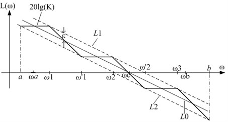
To improve the approximation accuracy, the approximation range contains the interested approximation band [].
The construction method is based on the minimum phase system. It can ensure that the phase frequency and amplitude frequency characteristics of the rational approximation function are consistent. The constructed rational approximation function is composed of n single real negative zeros and m single real negative poles. In order to achieve better approximation characteristics, let . The fractional-order integral operator is represented:
When 1, is a pure fractional-order integral operator. The [] is the interested approximation frequency band and is the crossing frequency of the logarithm amplitude frequency characteristic, .
First, the curve of Eq. (3) is shown by using line in Fig. 1. The other asymptote line and line are parallel to line . The amplitude error from and line to is (dB), which is the maximum permission error of the amplitude frequency characteristic. Line and line are given by:
Let ; the slope of the logarithm amplitude frequency characteristic curve is –20 in Eq. (3) and (4). The following equations are obtained:
The relationship among , and is described as:
From Eq. (5) and (6), the following equation is obtained:
Next, the detailed steps for obtaining best rational approximation function of fractional-order integral operator are described:
Step 1. Select the first turnover frequency .
Step 2. Draw a line segment with slope –20 dB/dec from the first turnover frequency on line ; this line segment can be represented as , which intersects line at frequency . For the frequency point , the following expression is obtained:
From Eqs. (5) and (8), the following equation is obtained: .
For the frequency point , the following equation is obtained:
From Eqs. (5) and (9), the following equation is obtained: .
Step 3. is obtained by crossing line with line . meets the following equation:
From Eq. (10), the following equation is obtained: .
The obtained and are the turnover frequencies of the first-order lagging link and second-order leading link respectively.
The previous steps are repeated until the turnover frequency of the th order 1agging link and turnover frequency of the th order leading link are obtained. The recursive calculative formulas are obtained:
where , 1, 2,….
If and are far greater than , they are removed and step 3 is terminated. At this time, an approximation function of is obtained.
Step 4. In the approximation range [], points with the same distance are selected, the difference between the value of and value of (1, 2,…, ) is calculated, and the maximum difference is selected as :
Step 5. Repeat step 1-4 for different values of to obtain rational approximation functions of .
Step 6. The minimum value of is selected from (1, 2,…, ).
Thus, , .
After all the steps, the approximation function of is obtained:
where .
Eq. (13) can be written as a general rational fractional expression:
where .
To verify the effectiveness of the proposed method, is approximated separately by Oustaloup’s method and the proposed method, and the results of approximation are compared. The approximation frequency range is [1, 10000]. when the approaching order is 3, the approximation results are obtained as follows:
At the same time, the approximation frequency range is [1, 10000], and the maximum approximation error of the amplitude frequency characteristic curve is 1.5 (dB); thus, the best rational approximation function of is written as:
The comparison of the Bode plots of the above two methods is shown in Fig. 2.
Fig. 2Comparison result of the two methods
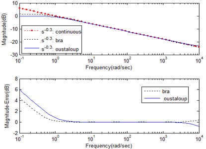
a) Amplitude frequency characteristic and error curve
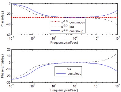
b) Phase frequency characteristic and error curve
As can be seen from Fig. 2(a), on the basis of analyzing the amplitude frequency characteristic and error curve, the result indicates that the proposed method better approximates the ideal curve in the approximation range. At the same time, this method compensates for the deficiency of the approximation effect of Oustaloup’s method in the near boundary point of the approximation interval. As can be seen from Fig. 2(b), on the basis of analyzing the phase frequency characteristic and error curve, the result indicates that the proposed method approximates the ideal curve better than Oustaloup’s method in the frequency range [1, 10]. The two methods deliver better approximation effects in the frequency range [10, 450], have certain approximation errors in the frequency range [450, 10000] and require further study.
In summary, on the basis of analyzing the amplitude frequency characteristic, phase frequency characteristic and error curve, the proposed method has a better approximation effect and compensates for the deficiency of the approximation effect of Oustaloup’s method to a certain extent.
4. Design of the fractional-order controller
4.1. Design steps for the fractional-order controller
Because this paper involves only the design idea for one fractional-order controller, it is independent of the values of the parameters. Thus, the selection parameters are not discussed, and the determined parameter values are randomly selected.
First, the fractional-order controller in the frequency domain is given:
The design steps of the fractional-order controller can be described.
Step 1. The values of the parameters () are initialized.
Step 2. The best rational approximation functions of fractional-order integral operators and are calculated by using the proposed method.
Step 3. The best rational approximation functions of and are substituted into Eq. (17), and a new equation is obtained.
4.2. A design case of a fractional-order controller
As can be seen from Eq. (17), the fractional-order controller includes five parameters: , , , , , .
In this paper, let , , , ,
Five parameters of controller are substituted into Eq. (17), and Eq. (18) is obtained:
Because the design is based on the best rational approximation method of fractional-order integral operators and the corresponding fractional-order integral operator is equivalent to a rational function, Eq. (18) can be rewritten as:
where , .
Let the approximation frequency band [, ] is [1,1000] and the maximum approximation error of amplitude frequency characteristic is 4 (dB). The best rational approximation functions of fractional-order integral operators and are calculated by the proposed method. Thus the best rational approximation equations of and are obtained:
Eqs. (20) and (21) are substituted into Eq. (19). Thus Eq. (22) is obtained:
Eq. (22) is the best rational approximation transfer function of fractional-order controller. Eq. (22) is transformed into Eq. (23) by the coefficient transformation:
Eq. (23) is used to describe the integer-order transfer function for the corresponding fractional-order controller. The amplification factor of the integer-order transfer function is 541.8. Its zeros and poles are shown in Table 1.
Table 1The zeros and the poles of integer order transfer function
No. | Zeros | Poles |
1 | –1.113 | –1.111 |
2 | –88.9 | –89.24 |
3 | –7162 | –7166 |
4 | –1701 | –7.691 |
5 | –13.9+j163.6 | –357 |
6 | –13.9-j163.6 |
5. Optimization and analysis of the frequency characteristics of fractional-order controller
To optimize and analyze the logarithmic frequency characteristics of transfer function, is used to replace in Eq. (23), and Eq. (23) is transformed into Eq. (24):
Next, the frequency characteristic of fractional-order controller is optimized and analyzed by using Eq. (24). The optimization removes partial zeros and poles, and the amplification factor of the transfer function is a constant. The steps of the optimization are explained:
1) The dipoles and outside the frequency band are removed, and the following Eq. (25) is obtained:
2) The zeros outside the approximation frequency [1, 1000] are removed, and the following transfer function of the controller is obtained:
3) Based on Eq. (26), the dipoles and are removed and the transfer function is obtained:
4) Based on Eq. (27), the dipoles and are removed and the transfer function is obtained:
5) Based on Eq. (28), one order leading link outside the approximation frequency [1, 1000] is removed, and the transfer function is obtained:
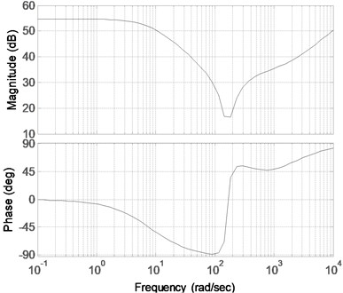
The corresponded logarithmic frequency characteristic curves of Eqs. (24)-(29) are shown in Fig. 3-Fig. 8, and the result of the comparison is shown in Fig. 9.
The Bode diagram of Eq. (24) is shown in Fig. 3. As can be seen from Fig. 3, the amplitude and phase of the controller changed greatly in the frequency band [100, 300] (rad/sec), and the maximum phase-lag was close to 90°. Fig. 4 shows the frequency characteristic curve obtained by removing a dipole nearby at 7000 rad/sec in Fig. 3. Because the dipole is far from the approximation band, Fig. 3 and Fig. 4 within the given frequency band do not change. Fig. 5 is obtained by removing the one order leading link outside the approximation frequency in Fig. 4. As can be seen from Fig. 5, the amplitude and phase became smaller in the high-frequency band. Because the one order leading link is much closer to the approximation frequency band, it exerts some influence on the high-frequency, as compared with Fig. 3.
According to the principle of automatic control, the reduction of amplitude will be beneficial for suppressing high-frequency interference, and the phase is still positive. Thus, the designed controller cannot decrease the system phase angle, which affects the system stability.
Fig. 3Bode diagram of the original rational approximation transfer function
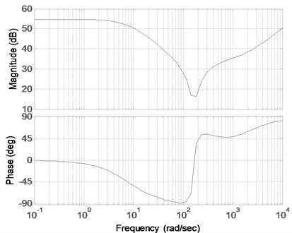
Fig. 4Bode diagram of the transfer function corresponding to Eq. (25)
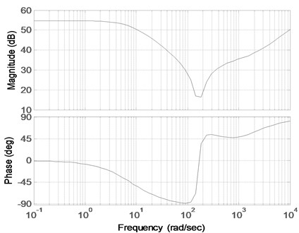
Two dipoles are located at the frequencies 1 rad/sec and 89 rad/sec on the approximation band. Fig. 6 shows a Bode diagram obtained by removing one dipole in Fig. 4. Fig. 7 shows a Bode diagram obtained by removing two dipoles in Fig. 4. Because the distance between the pole and zero is far smaller than the distance from the origin to the pole or zero, the influence of the amplitude and phase of the transfer function can be completely offset. Thus, Fig. 6 and Fig. 7 are close to Fig. 4. As can be seen from Figs. 4-7, the orders of the controller decreased; thus, the complexity is reduced by removing the dipole in the obtained transfer function.
Fig. 5Bode diagram of the transfer function corresponding to Eq. (26)
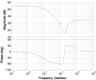
Fig. 6Bode diagram of the transfer function corresponding to Eq. (27)
To further simplify the structure of the controller based on maintaining the performance of the controller, Eq. (29) will be regarded as the controller model, and the order of the numerator and denominator is set to 2. The corresponding Bode diagram is shown in Fig. 8.
Fig. 7Bode diagram of the transfer function corresponding to Eq. (28)
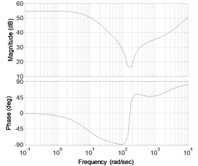
Fig. 8Bode diagram of the transfer function corresponding to Eq. (29)
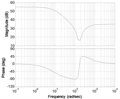
Fig. 9Comparison of bode plots
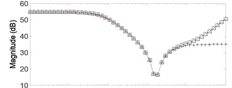
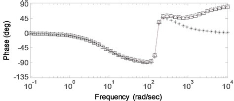
Fig. 9. is the comparison of the Bode diagrams. All the discussed characteristic curves are described in Fig. 9. It clearly shows that the removed dipoles will rarely affect the characteristic curves during the order reduction, but the reduction of one order leading link will obviously affect the high frequency of the characteristic curve. The final rational approximation transfer function of the fractional-order controller is shown below:
6. Conclusions
Based on the proposed best rational approximation definition of the fractional calculus operators, the construction method for the best rational approximation of a fractional-order integral operator is presented in this paper. The obtained approximation function in the frequency domain is the best rational approximation function, which can further improve the accuracy of approximation without increasing orders. The design and optimizing process of a fractional-order PID controller are also discussed. The final obtained fractional-order controller presents a good frequency characteristic, the best structure, easy realization and so on. This method is convenient, targeted to determining the controller model according to the given frequency band, and can be easily implemented with the program. This method can also provide better engineering applications of the fractional-order controller.
References
-
Machado J. T., Kiryakova V. M. Recent history of fractional calculus. Communications in Nonlinear Science and Numerical Simulation, Vol. 16, Issue 3, 2011, p. 1140-1153.
-
Podlubny I. Geometric and physical interpretation of fractional integration and fractional differentiation. Fractional Calculus and Applied Analysis, Vol. 5, Issue 4, 2002, p. 367-386.
-
Gu B., Sheng V. S., Keng Y. T., Romano W., Li S. Incremental support vector learning for ordinal regression. IEEE Transactions on Neural Networks and Learning Systems, Vol. 26, Issue 7, 2015, p. 1403-1416.
-
Machado J. T. Fractional derivatives: probability interpretation and frequency response of rational approximations. Communications in Nonlinear Science and Numerical Simulation, Vol. 14, Issue 7, 2009, p. 3492-3497.
-
Fu Z. J., Sun X. M., Liu Q., Zhou L., Shu J. G. Achieving efficient cloud search services: multi-keyword ranked search over encrypted cloud data supporting parallel computing. IEICE Transactions on Communications, Vol. E98-B, Issue 1, 2015, p. 190-200.
-
Gu B., Sun X. M., Sheng V. S. Structural minimax probability machine. IEEE Transactions on Neural Networks and Learning Systems, 2016.
-
Achar B. N., Hanneken J. W., Clarke T. Damping characteristics of fractional oscillator. Physica A, Vol. 339, 2004, p. 311-319.
-
Xia Z. H., Wang X. H., Sun X. M., Liu Q. S., Xiong N. X. Steganalysis of LSB matching using differences between nonadjacent pixels. Multimedia Tools and Applications, Vol. 75, Issue 4, 2016, p. 1947-1962.
-
Mozyrska D., Torres D. F. M. Modified optimal energy and initial memory of fractional continuous-time linear systems. Signal Processing, Vol. 91, Issue 3, 2011, p. 379-385.
-
Stojanovic M. Foundation of the fractional calculus in generalized function algebras. Journal of Applied Analysis, Vol. 10, Issue 4, 2012, p. 439-467.
-
Gu B., Sheng V. S., Wang Z. J., Derek H., Osman S., Li S. Incremental learning for ν-Support Vector Regression. Neural Networks, Vol. 67, 2015, p. 140-150.
-
Zheng Y. H., Jeon B., Xu D. H., Wu J. Q. M., Zhang H. Image segmentation by generalized hierarchical fuzzy C-means algorithm. Journal of Intelligent and Fuzzy Systems, Vol. 28, Issue 2, 2015, p. 961-973.
-
Wen S. F., Shen Y. J., Li X. D., Yang S. P., Xing H. J. Dynamical analysis of fractional-order Mathieu equation. Journal of Vibroengineering, Vol. 17, Issue 5, 2015, p. 2696-2709.
-
Ma T. H., Zhou J. J., Tang M. L., Tian Y., Al Dhelaan A., Al Rodhaan M., Lee S. Y. Social network and tag sources based augmenting collaborative recommender system. IEICE transactions on Information and Systems, Vol. E98-D, Issue 4, 2015, p. 902-910.
-
Wen X. Z., Shao L., Xue Y., Fang W. A rapid learning algorithm for vehicle classification. Information Sciences, Vol. 295, Issue 1, 2015, p. 395-406.
-
Li W., Hori Y. Vibration suppression using single neuron-based PI fuzzy controller and fractional-order disturbance observer. IEEE Transactions on Industrial Electronics, Vol. 54, Issue 1, 2007, p. 117-126.
-
Podlubny I. Fractional-order systems and PIλDµ controllers. IEEE Transactions on Automatic Control, Vol. 44, Issue 1, 1999, p. 208-214.
-
Tseng C. C. Design of fractional-order digital FIR differentiators. IEEE Signal Processing Letter, Vol. 8, Issue 3, 2001, p. 77-79.
-
Chen Y. Q., Kevin L. M. Discretization schemes for fractional-order differentiators and integrators. IEEE Transactions on Circuits and Systems I: Fundamental Theory and Applications, Vol. 49, Issue 3, 2002, p. 363-367.
-
Chen Y. Q., Vinagre B. M. A new IIR-type digital fractional-order differentiator. Signal Processing, Vol. 83, Issue 11, 2003, p. 2359-2365.
-
Podlubny I., Petras I., Vinagre B. M., O’Leary P., Dorcak L. Analogue realization of fractional-order controllers. Nonlinear Dynamics, Vol. 29, Issue 1, 2002, p. 281-296.
-
Krishna B. T. Studies on fractional-order differentiators and integrators: a survey. Signal Processing, Vol. 91, 2011, p. 386-426.
-
Oustaloup A., Levron F., Nanot F., Mathieu B. Frequency band complex non-integer differentiator: characterization and synthesis. IEEE Transactions on Circuits and Systems I: Fundamental Theory and Applications, Vol. 47, Issue 1, 2000, p. 25-40.
-
Charef A. Design of analog variable fractional-order differentiator. Nonlinear Dynamics, Vol. 69, Issue 4, 2012, p. 1577-1588.
-
Romero M., deMadrid A. P., Manoso C., Vinagre B. M. IIR approximations to the fractional differentiator/integrator using Chebyshev polynomials theory. ISA Transactions, Vol. 52, 2013, p. 461-468.
-
Chafia M., Youcef F. Using new hybrid integrators to design IIR fractional-order integrators via impulse invariance method. Circuits, Systems, and Signal Processing, Vol. 33, 2014, p. 643-653.
-
Tseng C. C., Lee S. L. Design of digital Feller fractional-order integrator. Signal Processing, Vol. 83, Issue 102, 2014, p. 16-31.
-
Benkhettou N., Brito da Cruz A. M. C., Torres D. F. M. A fractional calculus on arbitrary time scales: fractional differentiation and fractional integration. Signal Processing, Vol. 107, 2015, p. 230-237.
About this article
The authors would like to thank all the reviewers for their constructive comments. This research was supported by the National Natural Science Foundation of China (51475065, U1433124), Open Project Program of State Key Laboratory of Mechanical Transmissions (Chongqing University) (SKLMT-KFKT-201513, SKLMT-KFKT-201416), the Natural Science Foundation of Liaoning Province (2015020013), Open Project Program of Guangxi Key Laboratory of Hybrid Computation and IC Design Analysis (HCIC201507), Open Project Program of the Traction Power State Key Laboratory of Southwest Jiaotong University (TPL1403), PAPD and CICAEET.
