Abstract
Automotive brake squeal has become one of the major concerns in the automotive industry. The researches on suppressing brake squeal are of great practical significances. However, most of the existing researches have not taken into account the parameters uncertainties, although it is well known that uncertain factors widely exist in the brake systems. To reduce disc brake squeal more effectively, a practical approach for the stability analysis and improvement of an automotive disc brake system with fuzzy uncertainties is proposed. In the proposed approach, the uncertainties associated with friction coefficient, material properties and loading properties are taken into consideration, and the uncertain parameters of the brake system are represented by fuzzy numbers. The brake system stability is investigated by performing complex eigenvalue analysis (CEA), and response surface methodology (RSM) is employed to approximate the implicit relationship between the dominant unstable mode and system parameters. Then, the stability analysis model of the brake is constructed based on RSM, CEA and fuzzy analysis. As a numerical example, the stability analysis of a commercial disc brake system with fuzzy uncertainties is carried out, and the influences of different uncertain parameters on system stability are investigated. The analysis results show that the stability of the fuzzy brake can be improved effectively by increasing the specific modulus of back plate. The proposed approach can be considered as a potential method for squeal reduction of automotive disc brake systems under fuzzy case.
1. Introduction
The friction-induced vibration existing in the automotive disc brake systems can induce a dynamic instability, and cause an inconvenient squealing noise. The brake squeal noise with the frequency range from 1 to 16 kHz is considered to be most annoying [1]. Significant progress has been made in predicting and removing brake squeal and a large number of reviews have been presented on this subject [1-7]. Several classic theories have been formulated to explain the mechanisms of brake squeal phenomenon, such as stick-slip, sprag-slip, modal coupling and hammering excitation mechanism, et al. [7]. However, as pointed out by the literatures, the squeal reduction still remains a big challenge due to the complexity of this phenomenon.
Considerable numerical, analytical and experimental efforts have been spent on the squeal subject [4, 5]. The transient dynamic analysis and CEA are the two primary numerical approaches for squeal analysis [8-10]. For evaluating the stability of a brake system which reflects the likelihood of squeal noise, both the two methods are considered to be highly available. However, the former could only demonstrate whether a system is stable or not, but provide no insight into how the system could be altered to remove the instability. Compared with transient dynamic analysis, CEA is preferred and widely used, due to its quickness and usefulness in revealing the unstable modes and providing design guidance by analyzing different operating parameters virtually. Moreover, the effectiveness of CEA results has been already verified experimentally.
A lot of successful instances indicate that the numerical method of CEA based on finite element method (FEM) is an effective approach to understand, predict or prevent brake squeal. In the 1980s, Liles [11] constructed a FE model for determining the effects of several design parameters on brake system stability, and found that higher friction coefficient and wear of the friction material could increase squeal propensity. Subsequently, Lee et al. [12] presented an integrated approach for disc brake squeal analysis based upon a parametric FE model and found that thinner back plate of brake pad could increase squeal propensity. Nack [13] carried out brake squeal analysis by a large scale FE model under steady sliding condition, and found that the unstable modes were due to friction coupling of neighboring modes during squeal. Based on mode-coupling phenomenon, Fritz et al. [14] used a technique based on FEM to compute brake system eigenvalues, and the effects of damping on system eigenvalues were investigated. As an extension of the above studies, Ouyang et al. [15] solved the dynamic instability of a disc brake system as a nonlinear eigenvalue problem by developing a moving-load model. Sensitivity analysis was introduced to explore the influences of substructures parameters on system stability by Guan et al. [16]. The parametric analyses of disc brake system stability were carried out by Liu et al. [17] and Júnior et al. [18], where the influences of system key parameters on system stability were examined. Dai and Lim [19] carried out an optimization design of brake pads to show that the pads with radial chamfers had lesser brake squeal tendency. Based on detailed three-dimensional FE models, wear prediction of friction material in a disc brake system was presented by Abubakar and Ouyang [20], and the wear at the pad interface over time was simulated by Alberty [21] using a modified wear rate formula. By integrating FE simulations with statistical regression techniques, Nouby et al. [22] proposed a mathematical approach to investigate the influencing factors of brake pads on disc brake squeal. Within the past few years, Spelsberg-Korspeter [23] has performed a structural optimization for brake rotors and the mathematical difficulties of such an optimization are discussed.
It can be seen from the above-mentioned researches that brake squeal phenomenon has been deeply studied by the conventional deterministic procedures. In which, system parameters such as friction coefficient, material parameters and loading parameters are all assumed to be known precisely and defined exactly. At present, there are only a few studies investigating brake squeal problem by non-determined approaches. Chittepu [24] carried out a robustness evaluation of brake system stability with a stochastic model, in which the material scatters were modeled by random variables and the geometrical tolerances were modeled by random fields. Based on the polynomial chaos expansions and FEM, Sarrouy et al. [25] investigated the stability of a simplified disc brake system by stochastic simulations. The friction coefficient and the contact stiffness of the disc brake were modeled by random variables in this research. By introducing uncertainties and robustness concepts into squeal simulations, Tison et al. [26] proposed a complete strategy to improve the prediction of disc brake squeal. The strategy mainly relied on the integration of random fields into the contact interface, complex eigenvalue calculations and a robustness criterion. Lü and Yu [27, 28] proposed two different approaches for stability analysis and improvement of uncertain disc brake systems, in which the system parameters are treated as random variables or interval variables. It can be found that the investigations on uncertain brake squeal problem are still not comprehensive enough at present.
In practice, uncertainties associated with material, contact and loading properties are unavoidable in the automotive brake systems. The probabilistic methods are the most common approaches to cope with the uncertainties arising in practical engineering problems [29]. The existing studies [24-26] are all based on the popular probability methods. Actually, under some uncertain cases, it is difficult to determine the exact probability distributions of some uncertain parameters of the brake systems. For example, the friction coefficient cannot be measured directly and changes with respect to the sliding velocity between pads and disc, thus it is difficult to determine its probability distribution in some cases. Consequently, the non-probabilistic uncertainty models, such as interval model and fuzzy model, have been considered as useful alternatives to the probabilistic models.
The purpose of this study is to investigate and prevent the dominant unstable mode of a disc brake system with fuzzy uncertainties, so as to improve system stability and reduce squeal propensity. For this purpose, a practical approach for analyzing and improving the stability of the disc brake system with fuzzy uncertainties is presented. In the approach, the uncertainties of frictional coefficient, brake pressure and the mass densities, Elastic modulus and Poisson’s ratio of the materials are represented by fuzzy numbers. The stability analysis model of the brake is constructed based on CEA, RSM and fuzzy analysis. The effectiveness of the proposed approach on analyzing and improving the fuzzy brake system stability is demonstrated by a numerical example.
The probabilistic or interval approach in [27] and [28] appears to be quite helpless and no longer applicable for squeal analysis when fuzzy characteristics arise in the brake system. This proposed approach is an important part of the systematical study on uncertain squeal problem, and it will greatly improve and enrich the framework of the systematical study.
2. Fuzzy theory
2.1. Fuzzy sets and fuzzy numbers
The theory of fuzzy sets is an extension of the classical set theory as presented by Zadeh [30], and developed by many other researchers, including Kaufmann and Gupta [31]. For a classical crisp set, an element has a membership of either or and thus either belongs to the set or not. Contrary to a classical crisp set, the elements of a fuzzy set can have gradations of the membership between 0 and 1. A fuzzy set is uniquely defined by the following set of pairs:
where is an element of the fuzzy set, the tilde ∼ is used to symbolize fuzziness, is the domain of the fuzzy set and is the membership function for a fuzzy set and can be defined as:
It can be seen that the classical set is a special case of a fuzzy set in fact.
A fuzzy set is called fuzzy number if it is normal and convex. A detailed discussion on the fuzzy number is available in Ref. [32]. A fuzzy number is a special case of a fuzzy set and appears to be an ideal way of describing an uncertain parameter.
2.2. The -cut of a fuzzy number
The -cut approach is used to conduct the fuzzy arithmetic operations. The -cut of a fuzzy number can be defined as:
In other words, the -cut of a fuzzy number contains all the elements of the universal set whose membership grades in are greater than or equal to the specific value of . For each -cut level, we define an interval as:
where and are the lower and upper bounds of , respectively. and are the -values of and , respectively. Therefore, in the -cut approach, for different membership degrees in [0, 1], interval method is usually used to calculate the bounds of response.
2.3. Triangular fuzzy number
If the shape of the membership function is a triangle, the fuzzy number is called triangular fuzzy number, and can be expressed as [33]:
where and are the lower and upper bounds of the triangle at , respectively, and is the nominal value corresponding to . A triangular fuzzy number and its -cut of membership function can be seen in Fig. 1.
Fig. 1A fuzzy number and its α-cut
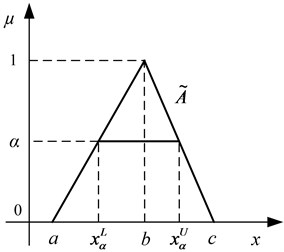
By the triplet number , the membership function of a triangular fuzzy number can be expressed as:
3. Response surface methodology
It is important to improve the stability performance of brake systems and the brake stability can be improved by the optimization of some system parameters. It is time-consuming and does not consider the combinational effects of different parameters in the conventional parameter designs of disc brake system stability, such as in [17] and [18].
RSM is a collection of statistical and mathematical methods. By this method the combinational effects of different system parameters to a system response can be fully considered. RSM has important applications in the design, development and formulation of new products, as well as in the improvement designs of the existing products [34]. In engineering design, RSM has been widely adopted to establish a mathematical relationship between the interesting responses and the design variables with a moderate number of FE analysis runs [35, 26].
Mathematically, the first and second order response surface (RS) models can be respectively defined as:
where is the response; is design variables; , , and are the estimated regression coefficients which can be obtained by the design of experiment (DOE) and the least square method (LSM) [34]; The cross product terms represent the two-parameter interactions and the square terms represent the second order nonlinearity; is the number of design variables.
Similarly, the third and fourth order RS models can be expressed, respectively, as:
After a RS model is established, its accuracy should be assessed. The analysis of variance (ANOVA) can be conducted to test the RS model, so as to ensure its fitting accuracy and significance [37].
4. Stability analysis and improvement of fuzzy disc brake system
4.1. A brake model and its stability analysis
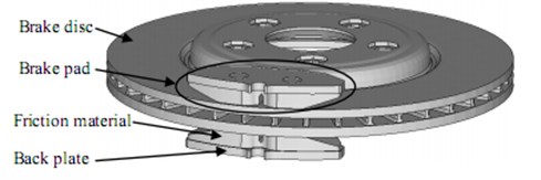
The simplified model of a disc brake system which consists of brake disc and brake pad assemblies is shown in Fig. 2. The simplified model has been previously considered and successfully used in some researches such as [8, 18, 25]. In the simplified model, the disc is rigidly mounted on the axle hub and is rotated with the wheel and the pair of brake pads consist of friction materials and back plates.
Fig. 2The simplified model of a disc brake system
During braking operation, the frictions between the disc and pads can induce a dynamic instability in the brake system. According to the existing researches, the stability of the brake system depends on the real parts of eigenvalues of the following complex eigenvalue problem [18]:
where and are the mass and damping matrices, respectively. is the structural stiffness matrix, and is the friction stiffness matrix which is determined by the pad-disc interface properties. is the eigenvalue and is the corresponding eigenvector. By the influence of friction, is an asymmetric stiffness matrix which may lead to complex eigenvalues and complex eigenvectors. The complex eigenvalue corresponding to the th complex mode of the brake system can be written as:
where and are the real and imaginary parts of , respectively. The brake system will be in an unstable state when the real part of one complex eigenvalue is positive. Therefore, the system stability can be reflected by the real parts of the complex eigenvalues.
Define the damping ratio of the th complex mode as [17]:
Apparently, the system will become unstable if is negative (i.e. ), and vice versa. There may not be a strict relationship between squeal and the magnitude of damping ratio (or real part) of brake system unstable eigenvalue. But just as the recent study [38] pointing out, many studies in the brake squeal research community take the damping ratios or the real parts as an index to evaluate the quality of a brake in terms of noise. Each car manufacturer accordingly sets a target value for the ‘squeal index’. If the absolute values of this index remain smaller than the target level from different CEA runs, this brake design will be considered acceptable. Furthermore, using the damping ratios or the real parts of the unstable eigenvalues as a ‘squeal index’ can also be found in [10, 17, 22, 38].
To analyze and improve the stability of a disc brake system, Computer Aided Engineering (CAE) allows us to precisely extract the complex eigenvalues of the system by FE simulations. To improve the efficiency of analysis, RS models can be used to replace the time-consuming FE simulations. By the second order RS models (Eq. (8)), the and of the complex eigenvalue can be expressed as:
where denote the system parameters; , , and are the regression coefficients for intercept, linear, interactive and quadratic coefficients of , respectively; , , and are the regression coefficients for intercept, linear, interactive and quadratic coefficients of , respectively; is the number of the system parameters. The surrogate models of brake system unstable eigenvalues have been successfully used to study system stability or squeal problem in [22], and in some very recent papers such as [38] and [39].
4.2. Brake system with fuzzy uncertainties
For the brake squeal problem, uncertainties in material, loading and contact properties are unavoidable. When introducing fuzzy uncertainties into the brake system, the RS models described by Eqs. (14) and (15) can be expressed as:
where is the vector of system fuzzy numbers; is the number of fuzzy numbers. Both and become fuzzy numbers accordingly due to the introduction of fuzzy uncertainties.
4.3. Calculation of system stability of the brake with fuzzy uncertainties
It is worth mentioning that the damping is not taken into account in the current study. Just as the recent Ref. [38] pointing out, the damping models of friction materials or other components have not been extensively studied at present and there is no reliable data on the damping of brake systems. In most cases, the damping can stabilize brake systems and excluding it will provide more potential unstable eigenvalues. Thus, industrial researchers tend to exclude the damping and set a target value for the damping ratio of an unstable eigenvalue in the CEA of practical engineering. If the damping ratio is not larger than the target value, the brake system will be considered as stable and acceptable [38]. Thus, this brake can be considered as a stable system when the damping ratio of the dominant unstable mode is greater than a constant , namely:
where is the damping ratio of the dominant unstable mode. is not a deterministic value but a fuzzy number, since it is determined by and . The dominant unstable mode can be chosen according to practical engineering and can be determined according to engineering requirement. Consequently, to evaluate the stability of a fuzzy disc brake system, one has to assess the fuzzy value of firstly.
As a successful practical application of fuzzy arithmetic, the Transformation Method [40] is used to evaluate in this research. Assuming the fuzzy brake system is characterized by fuzzy numbers , based on the interval arithmetic algorithm [41], the major steps of the evaluation of can be briefly described as follows
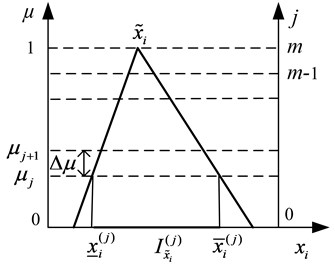
Step 1. Each fuzzy number (1, 2,…, ) is decomposed into a number of intervals , assigned to the membership levels (0, 1,…, ). The membership levels result from the subdivision of the axis of membership, into equally spaced intervals of length (shown in Fig. 3).
Step 2. The intervals (1, 2,…, ; 0, 1,…, ) are transformed to the arrays that are obtained from the lower and upper interval bounds after the application of a well-defined combinatorial scheme [40]. Each of these arrays represents a specific sample of possible parameter combinations and serves as an input parameter set to evaluate .
Step 3. As a result of the evaluation of the model for the input arrays , output arrays are obtained which are then retransformed to the output intervals for each membership level of .
Step 4. Finally, the intervals and the corresponding membership levels are recomposed to the fuzzy value of .
Fig. 3The decomposition of the fuzzy variable x~i
5. The procedures of stability analysis and improvement of the fuzzy brake system
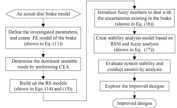
For squeal reduction, the stability analysis and improvement of a disc brake system with fuzzy uncertainties can be summarized and carried out as follows
Step 1. Create FE model of the simplified disc brake system (shown in Eq. (11)), and select investigated parameters;
Step 2. Obtain the unstable modes and determine the dominant unstable mode of the brake system, by performing CEA based on the FE model;
Step 3. Establish RS models of the complex eigenvalue corresponding to the dominant unstable mode (shown in Eqs. (14) and (15));
Step 4. Introduce fuzzy numbers to deal with the uncertainties existing in the brake system (shown in Eq. (16));
Step 5. Build up stability analysis model of the fuzzy brake system based on RSM and fuzzy analysis (shown in Eq. (17));
Step 6. Evaluate system stability and conduct sensitivity analysis;
Step 7. Analyze system stability, and explore the improved designs for squeal reduction.
The flowchart of the stability analysis and improvement of the brake system with fuzzy uncertainties is shown in Fig. 4.
Fig. 4Flowchart of the stability analysis and improvement of the brake system with fuzzy uncertainties
6. Numerical example
6.1. FE model of a simplified brake
The simplified disc brake shown in Fig. 2 is adopted for investigation in this section. In the simplified model, the disc is wear resistant and is made of grey cast iron. The friction materials of the pads are made of anisotropic composite material, and are mounted to the brake plate that made of steel. The three-dimensional FE model of the brake is illustrated in Fig. 5. The friction contact interactions are defined in the contact areas between the disc and the pads, in where the fine meshes are built.
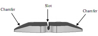
For this commercial brake, some common and effective measures have been taken to reduce the likelihood of squeal in the early design phase. For example, two chamfers and a slot have been provided on both sides and in the middle position of the friction material for each pad, as shown in Fig. 6. Therefore, the original system stability is relatively high.
Fig. 5The FE model of a simplified disc brake
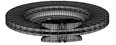
Fig. 6The chamfers and slot of the friction material
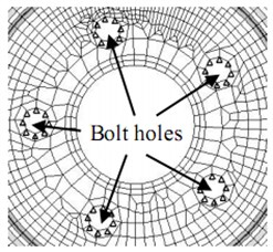
The constraints and loadings of this brake are shown in Fig. 7. The disc is completely fixed at the five counter-bolt holes. The back plates are constrained in the ears, and can just move along the axial direction. The brake pressure is directly acting on the back plate in the contact area between the pad and the piston, and an equal magnitude of brake pressure is similarly applied to the other back plate.
Fig. 7The constraints a) and loadings b) of the brake
a)

b)
The elastic property of the friction material is anisotropic and it is difficult to be defined. In this study, the friction material is treated as isotropic material but with varied Elastic modulus, just as in [18, 42]. In an uncertainty analysis, this assumption can be appropriate and acceptable. For this assumption, the uncertainty of the Elastic modulus of friction material in Table 3 is taken greater than that of other components.
The eigenvalue analysis of the brake system is dependent on a numerous of factors and mainly based on the stiffness and mass characteristics and operating conditions. Thus, the brake system parameters, we select to investigate, are: (1) the density , the Elastic modulus and the Poisson’s ratio of the material of back plate; (2) the density , the Elastic modulus and the Poisson’s ratio of friction material; (3) the density , the Elastic modulus and the Poisson’s ratio of the material of disc; (4) the brake pressure and friction coefficient .
Table 1The nominal values and the investigated ranges of brake system parameters
Parameter | Unit | Nominal value | Investigated range |
Density of back plate | kg/dm3 | 7.82 | [7.038, 8.602] |
Elastic modulus of back plate | GPa | 207 | [186.3, 227.7] |
Poisson’s ratio of back plate | / | 0.28 | [0.252, 0.308] |
Density of friction material | kg/dm3 | 2.51 | [2.259, 2.761] |
Elastic modulus of friction material | GPa | 5.94 | [4.752, 7.128] |
Poisson’s ratio of friction material | / | 0.3 | [0.270, 0.330] |
Density of disc | kg/dm3 | 7.2 | [6.480, 7.920] |
Elastic modulus of disc | GPa | 125 | [112.5, 137.5] |
Poisson’s ratio of disc | / | 0.24 | [0.216, 0.264] |
Brake pressure | MPa | 0.5 | [0.450, 0.550] |
Friction coefficient | / | 0.32 | [0.256, 0.384] |
The nominal values and the investigated ranges of these parameters are listed in Table 1. The investigated ranges are mainly used to build up the RS models.
In Table 1, the nominal values of system parameters are obtained from the supplier. The lower and upper variations of all parameters (except and ) are fixed at 10 % of the nominal values, respectively. Due to the assumption of the elastic property of friction material as previously mentioned, the lower and upper variations of are fixed at 20 % of its nominal values. The friction coefficient is the most important uncertain parameter in the analysis of squeal phenomenon, and its lower and upper variations are also fixed at 20 % of its nominal values by referring to the common ranges of .
6.2. Determination of dominant unstable mode
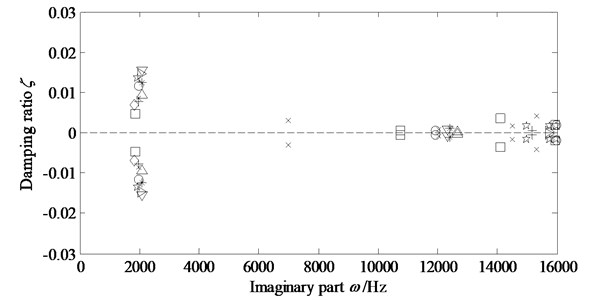
In this paper, Latin Hypercube Sampling [43] is used to generate 120 group samples to construct the RS models. Perform CEA based upon the FE model from 0 to 16 kHz, for each sample. It can be found that the unstable modes appear mainly around the frequency of 2 kHz. In some earlier studies such as [8, 22], the unstable mode at certain frequency is regarded as the dominant unstable mode. Therefore, the unstable mode at 2 kHz in our research is regarded as the dominant unstable mode whose damping ratio is negative. We will try to improve the system stability by increasing the negative damping ratio of the dominant unstable mode.
Fig. 8 shows the complex eigenvalues of the brake system corresponding to some group samples. The eigenvalues under the same group sample are represented by the same markers. It can be seen that the major unstable frequency is approximately 2 kHz.
Fig. 8The system complex eigenvalues under some group samples
6.3. Construction of RS models
The RS models of the real and imaginary parts of the complex eigenvalue corresponding to the dominant unstable mode are built up and marked as and , respectively. is the vector of investigated parameters.
Indeed, some other unstable modes can be found at other frequencies and the current RS models cannot present all unstable modes of the brake. However, the workload of considering all unstable modes is not affordable in the current investigation. Thus, just the dominant unstable mode is considered in this study. Furthermore, the main focus of this study is to propose a fuzzy numerical approach on squeal analysis and reduction instead of completely solving the squeal problem. The proposed approach remains the same regardless of the form of stability index, the type of design variables, and the number of input variables or unstable modes.
ANOVA is used to test the RS models and . The correlation coefficient is defined as the ratio of the explained variable to the total variation. For a good fit of a model, should be no less than 0.80 [43]. The values of obtained in the present study for and are 0.9828 and 0.9967, respectively. It indicates that the regression models can explain the observed responses well and are considered to be quite satisfactory. The -value is used as a tool to check the significance of the model. The RS model is considered to be statistically significant when the -value is lower than 0.05 [43]. Both the -values obtained in the present study for and are less than 0.0001. It confirms that the models are highly significant.
In order to test the predictability of the RS models of and , the complex eigenvalues produced by the original FE model and by the RS models for 10 group samples are shown in Table 2. It can be seen that the prediction accuracy of the RS models is very well.
Table 2The complex eigenvalues produced by the FE model and by the RS models
Sample | Real part | Imaginary part | ||
FE model | RS model | FE model | RS model | |
1 | 93.65 | 96.03 | 2054.50 | 2053.20 |
2 | 30.77 | 32.58 | 1963.40 | 1961.96 |
3 | 00.00 | 2.54 | 1851.00 | 1850.41 |
4 | 79.55 | 80.08 | 2047.50 | 2047.16 |
5 | 101.86 | 103.21 | 2117.60 | 2116.89 |
6 | 69.11 | 67.50 | 1983.80 | 1984.71 |
7 | 67.37 | 66.48 | 1907.80 | 1907.89 |
8 | 85.71 | 84.59 | 1856.40 | 1860.37 |
9 | 52.75 | 50.14 | 1964.20 | 1966.21 |
10 | 50.92 | 52.55 | 1897.20 | 1896.24 |
6.4. Brake system with fuzzy uncertainties
After introducing fuzzy uncertainties, the investigated parameters shown in Table 1 are all taken as fuzzy numbers and can be expressed as follows:
The fuzzy numbers are all assumed to have triangular membership functions. The lower and upper variations of , , , , , , , and are all fixed at 5 % of the nominal values; while the lower and upper variations of and are fixed at 10 % of their nominal values, respectively. In Table 3, the triplet numbers are used to define the triangular membership functions of the fuzzy numbers, and the middle values of the triplet numbers represent the nominal values of the fuzzy numbers.
Table 3Fuzzy numbers of the uncertain brake
Fuzzy number | Unit | Triplet number |
Density of back plate | kg/dm3 | [7.429, 7.82, 8.211] |
Elastic modulus of back plate | GPa | [196.65, 207, 217.35] |
Poisson’s ratio of back plate | [0.266, 0.28, 0.294] | |
Density of friction material | kg/dm3 | [2.385, 2.51, 2.636] |
Elastic modulus of friction material | GPa | [5.346, 5.94, 6.534] |
Poisson’s ratio of friction material | [0.285, 0.30, 0.315] | |
Density of disc | kg/dm3 | [6.84, 7.20, 7.56] |
Elastic modulus of disc | GPa | [118.75, 125, 131.25] |
Poisson’s ratio of disc | [0.228, 0.24, 0.252] | |
Brake pressure | MPa | [0.475, 0.5, 0.525] |
Friction coefficient | [0.288, 0.32, 0.352] |
6.5. Stability analysis of the fuzzy brake
By Eq. (17), the damping ratio of the dominant unstable mode of the fuzzy brake system can be expressed as:
Once the membership functions of the fuzzy numbers are obtained according to Table 3, the interval arithmetic techniques can be applied to Eq. (19) to estimate the response bounds at each -cut to get the membership function of . Ten levels of -cut (i.e., 0.1, 0.2, 0.3, 0.4, 0.5, 0.6, 0.7, 0.8, 0.9 and 1.0) are considered for each fuzzy numbers (, ) to calculate the membership function of . Fig. 9 shows the membership function of obtained by adopting the interval arithmetic techniques with 50,000 times Monte-Carlo simulations for each -cut. Table 4 shows the lower bound and upper bound of the membership function of at each -cut level.
Fig. 9The membership function of ζ~d
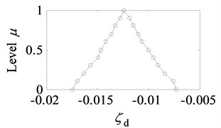
For a stable brake system, the damping ratio should be greater than –0.01 (namely –0.01) in engineering [28, 44]. The computational results of Fig. 9 and Table 4 show that the lower bounds of at each -cut level are all less than –0.01. The upper bounds of are also less than –0.01 at the -cut levels of 0.6 to 1.0. It indicates that is less than –0.01 for the most cases, namely that the robustness of this brake stability is very poor. Uncertain factors existing in the brake system are likely to destroy the system stability easily and thus increase the likelihood of squeal. Therefore, improvement designs are urgently to be taken to improve the stability of this brake.
Table 4The lower and upper bounds of the membership function of ζ~d at each α-cut level
-cut | |||
0 | 0 | –0.0174 | –0.0073 |
1 | 0.1 | –0.0170 | –0.0076 |
2 | 0.2 | –0.0163 | –0.0084 |
3 | 0.3 | –0.0157 | –0.0090 |
4 | 0.4 | –0.0150 | –0.0095 |
5 | 0.5 | –0.0147 | –0.0099 |
6 | 0.6 | –0.0141 | –0.0106 |
7 | 0.7 | –0.0136 | –0.0110 |
8 | 0.8 | –0.0133 | –0.0115 |
9 | 0.9 | –0.0128 | –0.0119 |
10 | 1.0 | –0.0124 | –0.0124 |
6.6. Sensitivity analysis
Sensitivity analysis is a very useful tool to explore the influence of system parameters on system stability, and it has been carried out for brake squeal investigation [16, 45, 46].
The stability of the brake system can be indicated by , therefore, the sensitivity of to the system parameter can be applied to show the influence of system parameters on system stability. The sensitivity analysis falls into two categories: sensitivity analysis and relative sensitivity analysis. There are no strict rules on selecting which concept as the criterion to evaluate the sensitivities of parameters. Usually the concept of sensitivity is employed when the independent variables are of the same scale, whereas the concept of relative sensitivity is adopted in the case that there are large differences on scales among the independent variables. Apparently, the latter concept is an ideal choice for this research.
The formula of relative sensitivity of to the system parameter can be given as [16]:
It should be emphasized that has negative correlation with while is positive, and vice versa. This is different from the conventional sensitivity analysis. It is because that is always positive, and is always negative, namely the items is always negative in this research. As a consequence, the relative sensitivity in this research has the opposite meaning, compared with the conventional sensitivity. In this research, is greater than zero, so by combining Eqs. (13) and (20), can be expressed as:
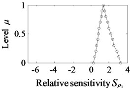
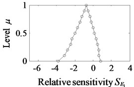
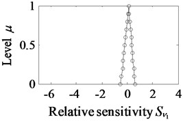
where . Referring to the work of Melchers and Ahammed [47], we assess the values of by Monte-Carlo simulations. Ten levels of -cut (i.e., 0.1, 0.2, 0.3, 0.4, 0.5, 0.6, 0.7, 0.8, 0.9 and 1.0) are considered for each fuzzy number as well, and the membership functions of are obtained by adopting the interval arithmetic techniques with 50,000 times Monte-Carlo simulations. The membership functions of are plotted in Fig. 10.
The following observations can be made from Fig. 10:
(1) The values of and are all or almost distributed among the positive territories of the horizontal axis, which means that is increased with the decrease of , , or . It indicates that the stability of this fuzzy brake system can be improved by low-density back plates, or by low-density friction materials, or by softer disc or by decreasing the friction coefficient.
(2) The values of and are all or almost distributed among the negative territories of the horizontal axis, which means that an increase of or can lead to a reduction of . It indicates that the stability of this disc brake system can be improved by stiffer back plates, or by high-density disc.
(3) The values of , , , and are all distributed on both sides of zero of the horizontal axis, which means that the value of either increases or decrease as , , , or increases.
Fig. 10The fuzzy values of relative sensitivity S~xi
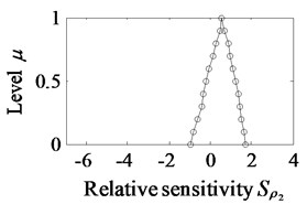
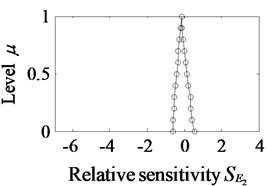
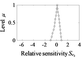
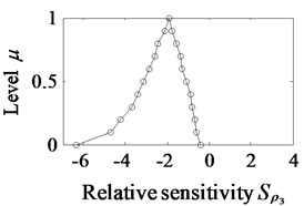
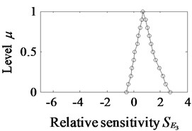
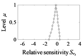
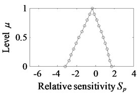
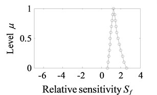
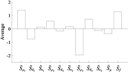
For displaying the influences of the fuzzy numbers on more directly, the average of is computed by 50,000 times Monte-Carlo simulations under the given uncertain values. Here the averages are listed in Table 5, sorted by ascending absolute values. The histogram of the averages of is also plotted and showed in Fig. 11.
Comparing the relative sensitivity values listed in Table 5 or shown in Fig. 11, we can find that:
(1) The first three sensitive parameters are , and , namely the density of disc, the density of back plate and the friction coefficient, have remarkable influences on under the given uncertain values.
(2) The least sensitive parameters are , , and , which means that the effects of the Poisson’s ratio of component material and the Elastic modulus of friction material on are not significant under the given uncertain values.
(3) The other parameters including , , and , namely the Elastic modulus of back plate, the density of friction material, the Elastic modulus of disc and brake pressure, have relatively obvious influences on under the given uncertain values.
Table 5The averages of S~xi under the given uncertain values
Order | Relative sensitivity | Average value |
1 | 0.1122 | |
2 | –0.1472 | |
3 | 0.1523 | |
4 | –0.1580 | |
5 | –0.3689 | |
6 | 0.5788 | |
7 | 0.7219 | |
8 | –0.7636 | |
9 | 1.2652 | |
10 | 1.3886 | |
11 | –1.9512 |
Fig. 11The histogram of the average values of S~xi
6.7. Improvement of system stability
From the above analysis, it can be known that the three direct and effective methods for improving the system stability are to improve the density of disc , or to reduce the density of back plate , or to reduce the friction coefficient . However, reducing will certainly reduce the braking performance, thus it is not a good solution. Nevertheless, reducing the density of back plate or increasing the density of disc can be easily achieved.
Towards the parameters (, , and p) which have relatively large sensitivity values, the density of frictional material and the brake pressure are inappropriate to be changed for improved design. It is because that it will be necessary to change the prescription and technical index to manufacture the composite if we change the density of frictional material ; and the brake pressure cannot be adjusted arbitrarily. By contrast, the Elastic modulus of back plate and the Elastic modulus of disc can easily be modified to improve the system stability, such as the application of stiffer back plate and softer disc. This is in agreement with the results of many studies such as [11] and [22].
Therefore, the parameters , , and are taken for improved design. With wider ranges of , , and listed in Table 6, the RS models are reconstructed (the other parameters take the ranges in Table 1). A total number of 120 group samples are used to build up the new RS models as well.
The effects of the density of back plate on system stability are studied by taking a series of fuzzy values for (the lower and upper variations of each fuzzy value are still fixed at 5 % of the nominal value), while taking the fuzzy values in Table 3 for the other variables. Fig. 12 shows the analysis results of system stability under different fuzzy values of .
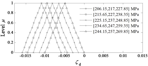
The effects of the Elastic modulus of back plate on system stability are also investigated by taking a series of fuzzy values for (the lower and upper variations of each fuzzy value are still fixed at 5 % of the nominal value), while taking the uncertain values in Table 3 for the other variables. The analysis results are shown in Fig. 13.
Table 6The new investigated ranges of ρ1, E1, ρ3 and E3 for improved design
Parameter | Unit | Nominal value | New investigated range |
Density of back plate | kg/dm3 | 7.82 | [6.4, 8.7] |
Elastic modulus of back plate | GPa | 207 | [185, 270] |
Density of disc | kg/dm3 | 7.2 | [6.4, 8.2] |
Elastic modulus of disc | GPa | 125 | [95, 138] |
Fig. 12Analysis results of system stability under different fuzzy values of ρ~1
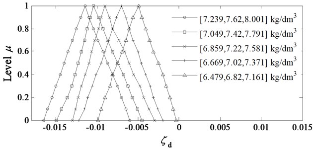
Fig. 13Analysis results of system stability under different fuzzy values of E~1
Likewise, the effects of the density of disc on system stability are also taken for investigation by taking a series of fuzzy values for (the lower and upper variations of each fuzzy value are still fixed at 5 % of the nominal value), while taking the uncertain values in Table 3 for the other variables. The analysis results are shown in Fig. 14.
In addition, the effects of Elastic modulus of disc on system stability are taken for investigation as well, by taking a series of fuzzy values for (the lower and upper variations of each fuzzy value are still fixed at 5 % of the nominal value), while taking the uncertain values in Table 3 for the other variables. The analysis results are shown in Fig. 15.
From Figs. 12-15, it is observed that the stability of this commercial brake system is increased as either the density of back plate or the Elastic modulus of disc decreases, or either the Elastic modulus of back plate or the density of disc increases. It is completely in agreement with the results of the sensitivity analysis as previously explained. Furthermore, it can also be found that when the nominal value of is 6.82 kg/dm3, or the nominal value of is 257 MPa, or the nominal value of is 7.8 kg/dm3, or the nominal value of is 100 MPa, the lower bounds of are all greater than –0.01, which means that the brake system will be in an absolutely stable state even though the influences of uncertain factors are considered.
Fig. 14Analysis results of system stability under different fuzzy values of ρ~3
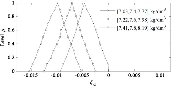
Fig. 15Analysis results of system stability under different fuzzy values of E~3
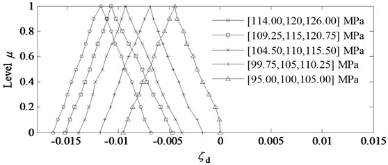
Fig. 16The effects of the specific modulus of back plate on ζ~d
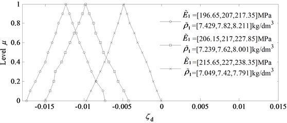
Fig. 17The effects of the specific modulus of disc on ζ~d
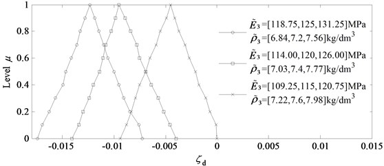
The Elastic modulus per unit density is called the specific modulus of material, and can be defined as . The effects of specific modulus of both the back plate and the disc on the system stability are also taken for investigation, and a series of values of both and are analyzed. The lower and upper variations of each fuzzy value of , , or are still fixed at 5 % of the nominal values. The analysis results are shown in Fig. 16 and Fig. 17.
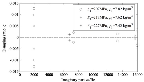
From Figs. 16 and 17, it can be seen that both increasing the specific modulus of back plate and decreasing the specific modulus of disc can improve the stability of this commercial brake system effectively. To verify this conclusion, several different CEA runs under different specific modulus of back plate have been performed. The results are shown in Fig. 18. It can be seen that the damping ratio of dominant unstable mode is increased with the increase of the specific modulus of back plate. By the same way, a negative correlation between the damping ratio and the specific modulus of disc can be found, which is not shown here.
Fig. 18The system complex eigenvalues under different specific modulus of back plate
Therefore, by increasing the specific modulus of back plates or decreasing the specific modulus of disc, it may improve the stability and robustness of the brake and reduce squeal tendency. In order to achieve the purpose of improving the specific modulus of back plate, one can change the material of back plate into the materials with larger Elastic modulus or lower density, alone or together. Moreover, one can make the back plate with composite materials in the conceptual design stage. Composite materials are considered to be stronger and stiffer than steel, but much lighter in weight, which enables them to have been widely used in aerospace engineering. As for changing the specific modulus of disc to improve system stability, this is a somewhat complex way, since it has to take into account the friction characteristic of the disc together.
7. Conclusions
A numerical approach is proposed to analyze and improve the stability of a fuzzy disc brake in this paper. In the proposed approach, the density, Elastic modulus and Poisson’s ratio of brake component materials, the brake pressure and the friction coefficient are taken as uncertain parameters and treated as fuzzy numbers. A stability analysis model of the fuzzy brake is constructed to explore the improved designs for squeal reduction, based on RSM, CEA and fuzzy analysis. In order to assess the influences of the fuzzy parameters on system stability, sensitivity analysis is undertaken. The combinational algorithm of the Transformation Method and the Monte Carlo method is employed to perform the uncertain analysis. The results of a numerical example show that increasing the specific modulus of back plate can effectively improve the system stability of the fuzzy brake. The proposed approach can be considered as a potential method for the improved design of brake squeal reduction under fuzzy case.
References
-
Yang S. Brake vibration and noise: reviews, comments, and proposals. International Journal of Materials and Product Technology, Vol. 12, Issues 4-5, 1997, p. 496-513.
-
Nishiwaki M. Generalized theory of brake noise. Proceedings of the Institution of Mechanical Engineers Part D, Journal of Automobile Engineering, Vol. 207, Issue 34, 1993, p. 195-202.
-
Papinniemi A., Lai J. C. S., Zhao J., et al. Brake squeal: a literature review. Applied Acoustics, Vol. 63, Issue 4, 2002, p. 391-400.
-
Kinkaid N. M., O’Reilly O. M., Papadopoulos P. Automotive disc brake squeal. Journal of Sound and Vibration, Vol. 267, Issue 1, 2003, p. 105-166.
-
Ouyang H., Nack W., Yuan Y., et al. Numerical analysis of automotive disc brake squeal: a review. International Journal of Vehicle Noise and Vibration, Vol. 1, Issues 3-4, 2005, p. 207-230.
-
Akay A., Giannini O., Massi F., et al. Disc brake squeal characterization through simplified test rigs. Mechanical Systems and Signal Processing, Vol. 23, Issue 23, 2009, p. 2590-2607.
-
Ghazaly N. M., Ahmed I., El-Sharkawy M. A review of automotive brake squeal mechanisms. Journal of Mechanical Design and Vibration, Vol. 1, Issue 1, 2014, p. 5-9.
-
Abubakar A. R., Ouyang H. Complex eigenvalue analysis and dynamic transient analysis in predicting disc brake squeal. International Journal of Vehicle Noise and Vibration, Vol. 2, Issue 2, 2006, p. 143-155.
-
Massi F., Baillet L., Giannini O., et al. Brake squeal: linear and nonlinear numerical approaches. Mechanical Systems and Signal Processing, Vol. 21, Issue 6, 2007, p. 2374-2393.
-
Qian W. J., Chen G. X., Zhou Z. R. Dynamic transient analysis of squealing vibration of a reciprocating sliding system. Wear, Vol. 301, Issues 1-2, 2013, p. 47-56.
-
Liles G. D. Analysis of disc brake squeal using finite element methods. SAE Technical Paper, 1989.
-
Lee Y. S., Brooks P. C., Barton D., et al. A study of disc brake squeal propensity using parametric finite element model. Transactions of IMechE European Conference on Noise and Vibration, 1998, p. 191-201.
-
Nack W. V. Brake squeal analysis by finite elements. International Journal of Vehicle Design, Vol. 23, Issues 3-4, 2000, p. 263-275.
-
Fritz G., Sinou J. J., Duffal J. M., et al. Investigation of the relationship between damping and mode-coupling patterns in case of brake squeal. Journal of Sound and Vibration, Vol. 307, Issues 3-5, 2007, p. 591-609.
-
Ouyang H., Mottershead J. E., Li W. A moving-load model for disc-brake stability analysis. Journal of Vibration and Acoustics, Vol. 125, Issue 1, 2003, p. 53-58.
-
Guan D., Su X., Zhang F. Sensitivity analysis of brake squeal tendency to substructures’ modal parameters. Journal of Sound and Vibration, Vol. 291, Issues 1-2, 2006, p. 72-80.
-
Liu P., Zheng H., Cai C., et al. Analysis of disc brake squeal using the complex eigenvalue method. Applied Acoustics, Vol. 68, Issue 6, 2007, p. 603-615.
-
Júnior M. T., Gerges S. N. Y., Jordan R. Analysis of brake squeal noise using the finite element method: a parametric study. Applied Acoustics, Vol. 69, Issue 2, 2008, p. 147-162.
-
Dai Y., Lim T. C. Suppression of brake squeal noise applying finite element brake and pad model enhanced by spectral-based assurance criteria. Applied Acoustics, Vol. 69, Issue 3, 2008, p. 196-214.
-
Abubakar A. R., Ouyang H. Wear prediction of friction material and brake squeal using the finite element method. Wear, Vol. 264, Issues 11-12, 2008, p. 1069-1076.
-
Alberty R. A. Finite element analysis of wear and its effect on squeal generation. Proceedings of the Institution of Mechanical Engineers Part D: Journal of Automobile Engineering, Vol. 222, Issue 7, 2008, p. 1153-1165.
-
Nouby M., Mathivanan D., Srinivasan K. A combined approach of complex eigenvalue analysis and design of experiments (DOE) to study disc brake squeal. International Journal of Engineering, Science and Technology, Vol. 1, Issue 1, 2009, p. 254-271.
-
Spelsberg-Korspeter G. Eigenvalue optimization against brake squeal: Symmetry, mathematical background and experiments. Journal of Sound and Vibration, Vol. 331, Issue 331, 2012, p. 4259-4268.
-
Chittepu K. Robustness evaluation of brake systems concerned to squeal noise problem. SAE Technical Paper, 2011.
-
Sarrouy E., Dessombz O., Sinou J. J. Piecewise polynomial chaos expansion with an application to brake squeal of a linear brake system. Journal of Sound and Vibration, Vol. 332, Issue 3, 2013, p. 577-594.
-
Tison T., Heussaff A., Massa F., et al. Improvement in the predictivity of squeal simulations: uncertainty and robustness. Journal of Sound and Vibration, Vol. 333, Issue 15, 2014, p. 3394-3412.
-
Lü H., Yu D. Stability analysis and improvement of uncertain disk brake systems with random and interval parameters for squeal reduction. Journal of Vibration and Acoustics, Vol. 137, Issue 5, 2015, p. 51003.
-
Lü H., Yu D. Brake squeal reduction of vehicle disc brake system with interval parameters by uncertain optimization. Journal of Sound and Vibration, Vol. 333, Issue 26, 2014, p. 7313-7325.
-
Stefanou G. The stochastic finite element method: past, present and future. Computer Methods in Applied Mechanics and Engineering, Vol. 198, 2009, p. 1031-1051.
-
Zadeh L. A. Fuzzy sets as a basis for a theory of possibility. Fuzzy Sets and Systems, Vol. 1, Issue 1, 1978, p. 3-28.
-
Kaufmann A., Gupta M. M. Introduction to Fuzzy Arithmetic. van Nostrand Reinhold, New York, 1991.
-
Nunes R. F., Klimke A., Arruda J. R. F. On estimating frequency response function envelopes using the spectral element method and fuzzy sets. Journal of Sound and Vibration, Vol. 291, Issues 3-5, 2006, p. 986-1003.
-
Balu A. S., Rao B. N. Explicit fuzzy analysis of systems with imprecise properties. International Journal of Mechanics and Materials in Design, Vol. 7, Issue 4, 2011, p. 283-289.
-
Baş D., İsmail H. B. Modeling and optimization I: Usability of response surface methodology. Journal of Food Engineering, Vol. 78, Issue 3, 2007, p. 836-845.
-
Akpan U. O., Koko T. S., Orisamolu I. R., et al. Practical fuzzy finite element analysis of structures. Finite Elements in Analysis and Design, Vol. 38, Issue 2, 2001, p. 93-111.
-
Fang J., Gao Y., Sun G., et al. Multiobjective reliability-based optimization for design of a vehicledoor. Finite Elements in Analysis and Design, Vol. 67, Issue 5, 2013, p. 13-21.
-
Richard F. G. Response surface methodology: process and product optimization using designed experiments. Technometrics, Vol. 38, Issue 3, 1996, p. 284-286.
-
Nobari A., Ouyang H., Bannister P. Uncertainty quantification of squeal instability via surrogate modelling. Mechanical Systems and Signal Processing, Vol. 60, Issue 61, 2015, p. 887-908.
-
Nechak L., Gillot F., Besset S., et al. Sensitivity analysis and Kriging based models for robust stability analysis of brake systems. Mechanics Research Communications, Vol. 69, 2015, p. 136-145.
-
Hanss M. The transformation method for the simulation and analysis of systems with uncertain parameters. Fuzzy Sets and Systems, Vol. 130, Issue 3, 2002, p. 277-289.
-
Moore R., Lodwick W. Interval analysis and fuzzy set theory. Fuzzy Sets and Systems, Vol. 135, Issue 1, 2003, p. 5-9.
-
Cao Q., Ouyang H., Friswell M. I., et al. Linear eigenvalue analysis of the disc-brake squeal problem. International Journal for Numerical Methods in Engineering, Vol. 61, Issue 9, 2004, p. 1546-1563.
-
Papila M. Accurate Response Surface Approximations for Weight Equations Based on Structural Optimization. Ph.D. Thesis, University of Florida, Florida, 2001.
-
Hou J., Guo X. X., Tan G. F. Complex mode analysis on disc brake squeal and design improvement. SAE Technical Paper, 2009.
-
Butlin T., Woodhouse J. Friction-induced vibration: quantifying sensitivity and uncertainty. Journal of Sound and Vibration, Vol. 329, Issue 5, 2010, p. 509-526.
-
Butlin T., Woodhouse J. Studies of the sensitivity of brake squeal. Applied Mechanics and Materials, Vols. 5-6, 2006, p. 473-480.
-
Melchers R. E., Ahammed M. A fast approximate method for parameter sensitivity estimation in Monte Carlo structural reliability. Computers and Structures, Vol. 82, Issue 1, 2004, p. 55-61.
About this article
The paper is supported by National Natural Science Foundation of China (Grant No. 11572121). The authors would also like to thank the editor and the reviewers for their valuable suggestions.
