Abstract
A non-pneumatic tire appears to have advantages over the conventional pneumatic tire in terms of flat proof and maintenance free. A mechanical elastic wheel (MEW) with a non-pneumatic elastic outer ring which functions as the air of the pneumatic tire was presented. The structure of MEW is non-inflatable integrated configuration and the effect of hinges is accounted for only in tension. To establish finite element model of MEW, various nonlinear factors, such as the geometrical nonlinearity, material nonlinearity and contact nonlinearity, were considered. Load characteristic test was conducted by tyre dynamic test-bed to obtain force-deflection curves. And the validity of the finite element model was validated through load characteristic test. The vehicle vibration performance respectively based on the MEW and the radial tire was compatative studied under pulse input experiment conditions. The result showed that the vehicle concluding the new mechanical elastic wheel met the vibration performance requirements and vibration performance regularity of pneumatic tire. The results could be used as the thesis reference for the improvement of new mechanical elastic wheel.
1. Introduction
Since the first commercial pneumatic bicycle tire by Dunlop in 1888, the pneumatic tire has been dominant in the world tire market for more than 100 years due to four major advantages it has over a rigid wheel: (i) low energy loss on rough surfaces, (ii) low vertical stiffness, (iii) low contact pressure, and (iv) low mass. However, the pneumatic tire has several disadvantages as well: (i) the possibility of catastrophic damage – a flat while driving, (ii) the required maintenance for proper internal air pressure, and (iii) the complicated manufacturing procedure [1].
Wheel and tire are as important components of vehicle driving system, which play an important role in riding comfort, and its main functions are to support vehicles, ease road impact, and generate driving or braking force. However, pneumatic tire burst at high speed may cause fatal traffic accident. According to statistics, 46 % of highway accidents were caused by tire failures, where tire burst accounted for 70 % of total accidents, and mortality rate caused by tire burst at a speed of more than 160 km was close to 100 % [2]. Therefore, developing run-flat and anti-puncture tire to guarantee high performance and security has become a consensus of the world’s major tire manufacturers.
To reduce the pneumatic tire disadvantages, several tire engineers have attempted to develop non-pneumatic tires, such as Uniroyal Goodrich Tire, Bridgestone, Toyo Tire and Tweel [3-8]. In this study, a mechanical elastic wheel (MEW) for a off-road vehicle which is a special kind of the non-pneumatic tire is proposed. Systematic research on its modeling, mechanical properties and trafficability indicate that the proposed wheel has small rolling resistance, good trafficability and other good characteristics [9-11]. The vehicle vibration performance respectively based on the MEW and the radial tire is comparative studied under pulse input experiment conditions. The research results provide references for optimization of wheel structure and vehicle dynamic.
2. MEW structure analysis
MEW breaks split design between traditional wheel and pneumatic tire, and adopts non-pneumatic structure which uses hinges group to connect elastic outer wheel and rigid wheel hub, so tire burst and puncture does not exist. The wheel consists of an elastic outer wheels, hinges group, wheel hub, return spring and other components, as shown in Fig. 1. Furthermore, elastic outer wheel consists of elastic rings, elastic ring clamps and rubber layer with tread patterns.
Fig. 1Structure of MEW
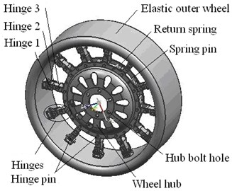
a) General assembly drawing of MEW
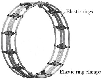
b) Structure of elastic ring mechanism
2.1. The structure of new mechanical elastic wheel
MEW is composed of the driving apron, elastic rings, the combo cards of elastic rings, hub, return spring, pins, hinges and other accessories. Its structure is shown in Fig. 1.
(1) 12 combo cards of elastic rings are distributed with the same angle and combined and locked a plurality of elastic rings together, as shown in Fig. 1(b).
(2) By burying vulcanization in the rubber layer of driving apron and inner layer of cord fabric, the elastic outer-wheel is built.
(3) The hub is put in the middle of the elastic outer wheel. One end of 12 groups of hinges is respectively installed with pins on the pin seat of the combo cards of elastic rings of the elastic outer wheel inner side. The other end of them is installed on the bolt hole of wheel hub.
(4) A return spring at the bottom of the third hinge connected to the hub. In free state, the groups of hinges are slightly bending deflection. Because of ground shocking and the driving and braking torque, the hinges are curved in the vehicle driving process. The curved hinges can be returned through the return spring.
2.2. The working principle of new mechanical elastic wheel
(1) The load and torque by axle passed the hub make the groups of hinges from flexuosity to pretension state. Then, the hinges pull the elastic outer-wheel. The force is making the wheel roll.
(2) The hub relying on the pull from the hinges hang into the outer-wheel and move down a distance due to vertical load. The hinges under the hub don’t subjected to force and are slightly curved. The upper part of elastic outer-wheel due to the downward pull from the hub, outer-wheel transform into the appropriate class of elliptic elastic deformation with setting range.
(3) Because of outer-wheel transforming into elliptic, the deformation of MEW is different from local deformation of the pneumatic tire under the driving process. It shows the rolling resistance and energy consumption of MEW is much smaller than that of the pneumatic tire and mechanical efficiency is much higher than that of the pneumatic tire.
(4) The MEW under the loading driving process, the force of each groups of hinges is from the tension gradually to the slightly bent not force, then to the tension, cycle replacement cycle. Because of the hub is put in the middle of the elastic outer wheel, the most of incentive of road roughness can only be suffered by the elastic outer-wheel. Because of deformation of the outer-wheel and the instantaneous curvature of each groups of hinges, incentive of road roughness cannot be sent to the wheel hub. The MEW has a specific mitigation and buffering isolation performance different from the pneumatic tire.
3. Finite element modeling of MEW
3.1. Establishment of Finite Element Model
Wheel outer elastic rims are simplified as four groups of elastic rigid rims which are fixed together by elastic rim clamps, and sharp corners of the structure, tire crown patterns and other factors are ignored. Simplified outer rim model of elastic wheel includes tire crown, belt, elastic rigid rim and tire carcass, as shown in Fig. 2(a). Fig. 2(b) is the finite element mesh model.
Fig. 23D FE model of an elastic wheel
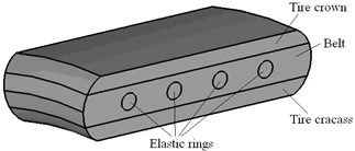
a) Structure of elastic outer wheel
b) 3D mesh model of MEW
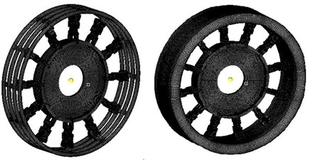
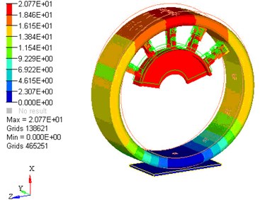
The mechanical elastic wheel model was meshed by HyperMesh, and due to the complex structure, mixed elements were used, where hexahedral element was in the majority, pentahedron element was in the minority. In order to guarantee certain grid density, the size of the element was based on to the structure. The main control parameters of element quality were as follows: the maximum length-width ratio was 3, the minimum Jacobi was 0.8, the maximum surface distortion was 35°, the minimum quadrilateral interior angle was 50°, the maximum quadrilateral interior angle was 130°, the minimum triangle interior angle was 45°, and the maximum triangle interior angle was 75°. The model was divided into 307632 body elements, with a total of 374774 nodes, and minimum element size was controlled in 2 mm. After meshing, element continuity and grid quality of repetitive elements were check, to ensure the grid deformation was in a certain range. Deformation of MEW under vertical load is shown in Fig. 3.
Fig. 3Deformation of MEW finite element model
The main contacts in the wheel model were: elastic ring and outer wheel, elastic ring and hinge, internal hinge, hinge group and wheel hub. The main contacts above were defined according to the characters of wheel structure and movement relationships between each component. The element rbe2 was used between elastic ring and outer wheel, and the rest of the contacts were revolute pair with mutual movement. Therefore, the contacts with the other three parts were defined as sliding contact, and sliding friction coefficient was 0.15.
3.2. Nonlinear characteristic of MEW
Outer rim of elastic wheel has a hierarchical structure, so nonlinear factors of materials and boundary conditions need to be considered in modeling, in addition, large deformation and nonlinear effects of contact with ground should be considered because wheel deformation is mainly undertaken by elastic outer rim. Rubber entity unit of mechanical elastic wheel uses approximate incompressible super elastic rubber material model; which incompressibility condition is represented by Poisson ratio 0.48.
Tire tread model uses Mooney-Rivlin material according to characteristics of this study. The structural relationship of rubber materials is complex nonlinear functions, which can be expressed by Mooney-Rivlin strain energy density function, and its expression is:
where, , , are material constants.
The typical two third-order expansion of Mooney-Rivlin strain energy density function is widely used, and when the strain is within 150 %, most rubber materials can receive reasonable approximation, as shown in Eq. (2):
where, , , are strain invariants represented by primary elongations, and for incompressible material, 1.
Furthermore, considering viscoelasticity characteristics of rubber materials, Prony series model is generally used to express its viscoelasticity, and its expression is:
where, is shear relaxation modulus, is volume relaxation modulus, is shear relaxation modulus factor of the series , is volume relaxation modulus factor of the series , and is relaxation time.
The wheel has typical large deformation characteristics when working, so it is limited that using traditional linearelastic small strain theory to study structural mechanics. Therefore, geometric nonlinearity large deformation theory must be considered. Total Lagrange is used to solve geometric nonlinearity, and the relationship between Green strain and Kirchhoff stress based on the principle of virtual work is:
Then use variation method:
Finite element equation matrix with geometric nonlinearity TL method can be expressed as:
where, is tangent stiffness matrix, presenting the relationship between load increment and displacement, is initial
stress stiffness matrix or geometric stiffness matrix, presenting the effect of initial stress on the structure in large deformationcases, is initial displacement stiffness matrix or large displacement stiffness matrix, presenting structure stiffness changes along with large displacement, is node coordinates increment vector, is body load vector, is surface load vector, and is stress equivalent resultant force vector on the node.
There are two contacts, elastic rigid rim and rubber material, tire tread and ground, in mechanical elastic wheel finite element model, and them belong to functional extreme value problem with constraints, so penalty function method is used to predict normal force, and Coulomb friction model should be used to predict tangential force.
Normal force is:
where, is normal contact stiffness, and is gap value determined by contact node position relative to target surface.
Tangential force is:
where, is shear stiffness, is elastic deformation of contact node relative to target surface, and is sliding coefficient of friction.
Fig. 4Load-deflection curve of MEW
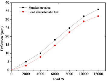
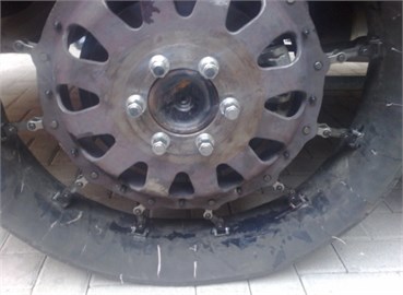
Fig. 5A vehicle equipped with MEW
3.3. Validation of Finite Element Model
To verify the model, load characteristic test was conducted, and compared the results with prototype load characteristic curve, as shown in Fig. 4. The load characteristic test is shown in Fig. 5.
The figure shows that load characteristic curve of mechanical elastic wheel is nearly linear, simulation results are consistent with experimental results, which verifies that the finite element model can accurately reflect actual bearing of elastic wheel. All these researches establish foundation for vibration characteristic analysis of the wheel at still state.
4. Vibration performance analysis of Vehicle in the impulse input experiment
4.1. Experiment method
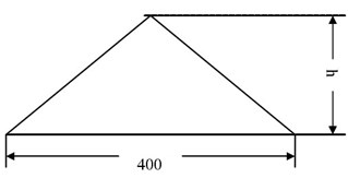
According to national standard GB/T4970-2009: the triangle single bump method is used in pulse input experiment shown as in Fig. 6. The hemline length and the height of triangle bump are respectively 400 mm and 80 mm. The off-road vehicle drives through bump at the speed of 20, 40, 60, 80, 100 km/h. The maximum vertical acceleration is used to evaluate vehicle.
Fig. 6Triangle bump
4.2. Comparative analysis of the experiment results
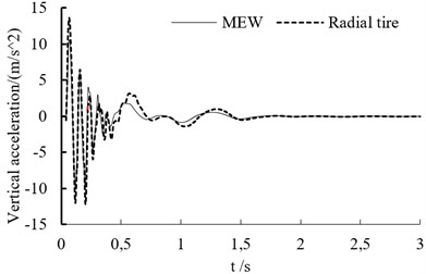
In the experiment, the test point is set on the vehicle’s mass center. The vertical acceleration curve at different speed is shown as in Fig. 7. When the off-road vehicle drives through bump, it endure the big shock. Whether the vehicle is based on the mechanical elastic wheel or the radial tire, the acceleration variation trend is similar at different speeds.
When the speed is lower than 60 km/h, the acceleration peak value increases with vehicle’s speed.
Table 1 is the vertical acceleration values of off-road vehicle based on the MEW at different speeds and Table 2 is the vertical acceleration values of off-road vehicle based on the radial tire at different speeds. The vertical acceleration peak values of off-road vehicle based on MEW increase firstly and then decrease with the increasing speed. The vertical acceleration peak values of off-road vehicle based on the radial tire increase firstly and then remain unchanged with the increasing speed. The peak vertical acceleration of both tires at different speeds are similar.
Table 1The vertical acceleration values of off-road vehicle based on the MEW at different speeds
Speed(km/h) | 20 | 40 | 60 | 80 | 100 |
vertical acceleration(m/s^2) | 10.7 | 11.1 | 11.1 | 11.0 | 10.8 |
Table 2The vertical acceleration values of off-road vehicle based on the radial tire at different speeds
Speed(km/h) | 20 | 40 | 60 | 80 | 100 |
vertical acceleration(m/s^2) | 12.6 | 13.5 | 13.7 | 13.7 | 13.7 |
Referring to the international criteria ISO2631-1 of health assessment method for systemic exposure vibration, if the maximum acceleration response transferred to passenger by the surface of the seat cushion is greater the 43.02 m/s2, it will do harm to the human body. If it is smaller than the 31.44 m/s2, there is nothing to do with the human body health. And if the acceleration response lies in the range of 31.44-43.02 m/s2, a certain extent of harm will put on human body. As can be seen from the Table 1 and Table 2, whether the vehicle is based on the mechanical elastic wheel or the radial tire, the maximum acceleration response values are less than 31.44 m/s2. The off-road vehicle respectively based on the MEW and the radial tire meet the vibration performance requirements in the impulse input experiment.
Fig. 7The vertical acceleration curve at different speed
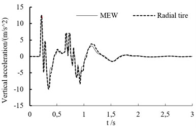
a) Vertical acceleration of vehicle mass center at the speed of 20 km/h
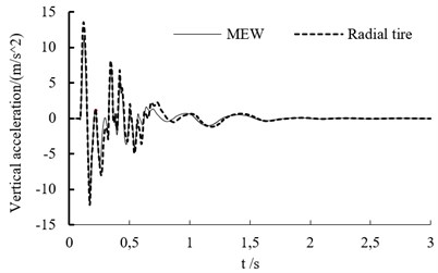
b) Vertical acceleration of vehicle mass center at the speed of 40 km/h
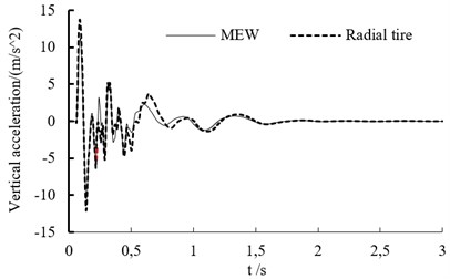
c) Vertical acceleration of vehicle mass center at the speed of 60 km/h
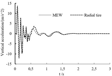
d) Vertical acceleration of vehicle mass center at the speed of 80 km/h
e) Vertical acceleration of vehicle mass center at the speed of 100 km/h
5. Vehicle ride quality simulation comparison
In this paper, the mechanical elastic wheel model and the vehicle model are built in the using ADAMS. In this paper vehicle model, ride comfort of vehicle between mechanical elastic wheel and the radial tire are comparative analyze. The vehicle is set in the B road at 60 Km/h speed. Comparing the results of ride quality based on the mechanical elastic wheel vehicle centroid and the general radial tire vehicle centroid, we can get the acceleration curves of the axis (vertical), axis direction (lateral) and axis direction (radial) shown in Figs. 8 and 9.
Fig. 8The acceleration curves of the X axis, Y axis and Z axis on MEW
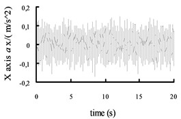
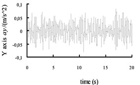
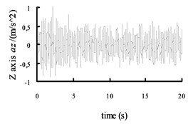
Fig. 9The acceleration curves of the X axis, Y axis and Z axis on the radial tire
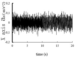
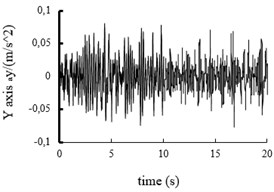
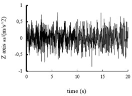
Fig. 10The acceleration power spectral density curves of the X axis, Y axis and Z axis on MEW
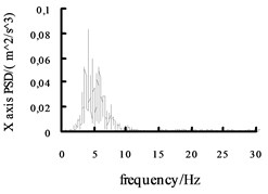
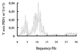
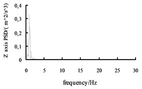
Fig. 11The acceleration power spectral density curves of the X axis, Y axis and Z axis on the radial tire
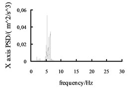
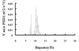
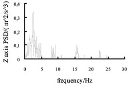
Using the Fast Fourier Transform (FFT) function of ADAMS post-processing to put the each direction acceleration curves into the acceleration power spectral density curves, and then the curves are obtained, shown in Fig. 10 and Fig. 11. It can be seen from the figure: the level , direction acceleration power spectral density peak value of the vehicle based on the mechanical elastic wheel appear near the 4.2 Hz and 10.7 Hz position, avoiding 0.5-2 Hz sensitive range; while, the , direction acceleration power spectral density peak of the vehicle based on the radial tire appears near the 5.6 Hz and 11.5 Hz position, also avoiding 0.5-2 Hz sensitive range. From Fig. 10 and Fig. 11, we can see the vertical acceleration power spectral density peak of the vehicle based on the mechanical elastic wheel appears near the 1.1 Hz position, avoiding 4-12.5 Hz sensitive range. While, the vertical acceleration power spectral density peak of the vehicle based on the pneumatic tire near the 2.5 Hz position, also avoiding the sensitive range of 4-12.5 Hz.
From the analysis above, mechanical elastic wheel can replace the role of the radial tire in Ride Comfort. According to the ISO 2631-1:1997 (E) standard, each axial frequency weighting function is get from the Eq. (9). Each axial weighted acceleration mean square value , , are obtained according to the formula 10 and 11 in the ADAMS post-processing:
In the same method, each axial weighted acceleration root-mean-square value and the total weighted root-mean-square acceleration are obtained at 40, 50, 70 km/h speed, the results are showed in Table 3 and Table 4.
The results can be obtained from the two tables:
1) As the speed increasing, the weighted acceleration root-mean-square value becomes large. It means that the ride comfort of the vehicle decreased with speed increasing. The ride comfort of the vehicle based on the radial tire at the different speed is slightly better than that of the mechanical elastic wheel, but the ride Comfort of the vehicle based on the mechanical elastic wheel satisfy with the regularity of the ride comfort of the vehicle based on the radial tire and conform with the characteristics of the radial tire.
2) According to the weighted acceleration root-mean-square value and human subjective feeling: when weighted acceleration is less than 0.315 m/s2, the body is not uncomfortable. No matter based on the mechanical elastic wheel or the radial tire, the body is not uncomfortable when the vehicle speed is less than 60 km/h in B road. The mechanical elastic wheel is committed to improve the controllability and stability of vehicle. So when the vehicle with mechanical elastic wheel drive at the speed of 70 km/h, driver’s seat vibration response exceeds slightly the limit and the body has some uncomfortable. When the vehicle with the radial tire drive at the speed of 70 km/h, driver’s seat vibration response does not exceed the limit, the human feel comfortable. So, the ride comfort of mechanical elastic wheel under the condition of high speed needs to be improved.
Table 3Each axial weighted acceleration root-mean-square value on MEW
Speed (km/h) | (m/s2) | (m/s2) | (m/s2) | (m/s2) | Human subjective feeling |
40 | 0.0799 | 0.0468 | 0.2237 | 0.2585 | Comfortable |
50 | 0.0869 | 0.0539 | 0.2454 | 0.2841 | Comfortable |
60 | 0.1015 | 0.0715 | 0.2484 | 0.3032 | Comfortable |
70 | 0.1163 | 0.0762 | 0.2671 | 0.3305 | Some uncomfortable |
Table 4Each axial weighted acceleration root-mean-square value on the radial tire
Speed (km/h) | (m/s2) | (m/s2) | (m/s2) | (m/s2) | Human subjective feeling |
40 | 0.0639 | 0.0388 | 0.1422 | 0.1766 | Comfortable |
50 | 0.0768 | 0.0443 | 0.1451 | 0.1909 | Comfortable |
60 | 0.0896 | 0.0507 | 0.1543 | 0.2111 | Comfortable |
70 | 0.0984 | 0.0649 | 0.2445 | 0.2950 | Comfortable |
6. Conclusions
In this study, a kind of new mechanical elastic wheel used for vehicle is put forward, to improve the tire performance of puncture-proof, explosion prevention, safety and bullet-proof. MEW integrated tire and wheel combination is one of non-pneumatic tire which has potential for improved handling, grip, low energy loss when impacting obstacles and reduced rolling resistance when compared to a pneumatic tire. The objective of this study is to analysis vehicle vibration performance analysis with the non-pneumatic new mechanical elastic wheel in the impulse input experiment.
1) A new mechanical elastic wheel is non-pneumatic structure, which uses hinge groups to connect outer rim of elastic wheel and wheel hub, so it provides a new research idea for solving tire burst and puncture problems of pneumatic tires.
2) The vehicle vibration performance respectively based on the MEW and the radial tire was comparative studied under pulse input experiment conditions. The off-road vehicle drives through bump at the speed of 20, 40, 60, 80, 100 km/h. The result showed that the vehicle concluding the new mechanical elastic wheel met the vibration performance requirements and vibration performance regularity of pneumatic tire. The results could be used as the thesis reference for the improvement of new mechanical elastic wheel.
References
-
Gent A. N., Walter J. D. The Pneumatic Tire. National Highway Traffic Safety Administration, Washington, D.C., 1985.
-
In G. J., Young H. S., Eui J. Y., et al. Pattern design of a non-pneumatic tyre for stiffness using topology optimization. Engineering Optimization, Vol. 42, Issue 2, 2011, p. 119-131.
-
Rhyne T., Cron S. M. Development of a non-pneumatic wheel. Tire Science and Technology, Vol. 34, Issue 3, 2006, p. 150-169.
-
Ju J., Ananthasayanam B., Summers J. D., et al. Design of cellular shear bands of a non-pneumatic tire-investigation of contact pressure. SAE International Journal of Passenger Cars-Mechanical Systems, Vol. 3, Issue 1, 2010, p. 598-606.
-
Jang I. G., Sung Y. H., Yoo E. J., et al. Pattern design of a non-pneumatic tyre for stiffness using topology optimization. Engineering Optimization, Vol. 44, Issue 2, 2012, p. 119-131.
-
Ju J., Kim D. M. Flexible cellular solid spokes of a non-pneumatic tire. Composite Structures, Vol. 94, Issue 8, 2011, p. 2285-2295.
-
Manga K. K. Computation Method for Solving Spoke Dynamics on High Speed Rolling Tweel™. Master’s Thesis, Clemson University, Clemson, SC, 2008.
-
Ramachandran M. Nonlinear Finite Element Analysis of Tweel™ Geometric Parameter Modifications on Spoke Dynamics during High Speed Rolling. Master’s Thesis. Clemson University, Clemson, SC, 2008.
-
Yue H. X., Zhao Y. Q. Nonlinear finite element analysis of a new safety wheel. China Mechanical Engineering, Vol. 23, Issue 11, 2012, p. 1380-1385.
-
Wang W., Zhao Y. Q., Huang C., et al. Modeling and trafficability analysis of new mechanical elastic wheel. China Mechanical Engineering, Vol. 24, Issue 6, 2013, p. 724-729.
-
Rhyne T. B., Cron S. M. Development of a non-pneumatic wheel. Tire Science and Technology, Vol. 34, Issue 3, 2006, p. 150-169.
Cited by
About this article

This work is partially supported by the National Science Foundation of China (Grant No. 51305175), the National Science Foundation of JiangSu Province (Grant No. BK2012586), the National Science Foundation of Jiangsu University of Technology (Grant No. KYY14041), the 333 Project of Jiangsu Province (BRA2015365) and Jiangsu Province “Six Personnel Peak” Fund Projects (Grant No. 2012-ZBZZ-023) and (Grant No. 2013-ZBZZ-039). The authors gratefully acknowledge the helpful comments and suggestions of the reviewers, which have improved the presentation.
Wang Wei – vibration performance analysis of vehicle in the impulse input experiment. Zhu Kai – MEW structure analysis. Bei Shaoyi – establishment of finite element model. Zhang Lanchun – comparative analysis of the experiment results. Wang Yongzhi vehicle ride quality simulation comparison.
