Abstract
A field test of environment vibration due to subway was carried out so as to investigate the vibration-alleviating effect of rail suspension fasteners in both time and frequency domains. The experimental results show that the time-domain vertical ground vibration accelerations would transform from several concentrated vibrations to the decentralized and uniform ones after replacement of common rail fasteners with rail suspension fasteners. Moreover, rail suspension fasteners have more significant vibration-mitigation effect on the time-domain peak particle accelerations (PPAs) at the nearer positions than at the farther ones, and the minimum PPA induced by common rail fasteners is still higher than the maximal PPA caused by rail suspension fasteners at all measuring positions. In frequency domain, the vibration-reduction effect of rail suspension fasteners is more remarkable in the dominant 1/3 octave center frequencies of 50-125 Hz than in the non-dominant ones from 1 to 40 Hz. Compared with common rail fasteners, the highest vibration acceleration levels (VALmax) in the dominant 1/3 octave center frequencies between 50 and 125 Hz at all measuring positions decrease by 8.7-21 dB after adoption of rail suspension fasteners. Additionally, the integrated VLzs in 1/3 octave center frequencies of 1-125 Hz at all measuring positions are ranged from 77.1 dB to 66.5 dB, evidently higher than the China’ standard threshold of 65 dB, before replacement of common rail fasteners, while the integrated VLzs are framed between 68.3 and 57.3 dB, mostly less than the threshold, after application of rail suspension fasteners.
1. Introduction
It is undoubted that mass construction of subway can supply with many advantages, such as saving land, facilitating travel, conserving energy, reducing air pollution and so on. Certainly, there are also inevitably some disadvantages, including high construction cost and disturbing vibration or noise. Especially, with the increasing of operating time and the worsening of track irregularity and wheel polygon, the vibration and noise nuisances generated by subway are bound to catch more and more attention.
So far, there have been a large proportion of in-situ tests performed near subway lines for capture of train-induced ground vibration, which are helpful for understanding of train-induced vibration migration in both time and frequency domains. The existing experimental results show that the different track formers definitely give rise to the different characteristics of vibration propagation. Xia et al. [1] carried out a field experiment at the trial section of an elevated bridge on Beijing Metro Line 5 with the ladder track installed. The measured data indicated that the vibration-reduction effect of the ladder track was better than that of the common non-ballasted slab track in most frequency bands of 1-5 Hz and above 10 Hz. However, in the frequency band of 5-10 Hz, the vibration-alleviating effect of the ladder track was slightly less than that of the common non-ballasted slab track. In addition, there were also six sections of track monitored in Spain, involving a tram slab track with rail embedded in rubber elastomer, a metro slab track resting with elastomeric soles resting directly the slabs, three types of metro ballasted track with a clip fastening system and a high-speed ballasted track. It seemed that the slab and ballasted track of metro lines had similar vibration alleviation at roughly the same pattern, however after analyzing the spectra, ballasted track tended to perform slightly better when dealing with lowest frequency bands [2]. Hui et al. [3] measured the performance of several isolation designs to control vibration transmissions from concrete rail viaducts in Japan, Korea and Hong Kong. It was found that the bending resonance of a floating slab had a negative influence on the vibration isolation performance, especially when it was close to the passage support frequency or vertical natural frequency. Saurenman et al. [4] presented results of a number of vibration measurements of the different track forms used on the San Francisco Bay Area Rapid Transit (BART) system including floating slab, resiliently supported half-ties (LVT track) and high-resilience direct fixation fasteners in subway and one section of floating slab used on at-grade track. One of the noticeable conclusions was that the high-resilience Egg fasteners might reduce vibration levels by 5-8 dB at frequencies greater than 25-30 Hz. Another exploration of ground-borne vibration characteristics was performed at six sites in the Boston area. It was concluded that the frequency range of significant velocity level for subway travelling on the ballasted track was in the range of 10-250 Hz and the peak vibration levels were typically in the frequency range from 20-40 Hz [5]. Although train-induced vibration characteristics between subway and high-speed railway are different, the measured environment vibration caused by high-speed railway is also beneficial for vibration control of subway in a certain extent. There have been a lot of field tests recorded for the environment vibration induced by the ballasted [6-8] or non-ballasted [9] track of high-speed railway. It is worth noting that Connolly et al. [10] performed a detailed statistical analysis of over 1500 ground-borne vibration records, at 17 high speed rail sites, across 7 European countries. Some new insights into the prediction of ground-borne vibration were presented.
Certainly, the above measured data about environment vibration due to railway were usually also applied for validation of the theoretical or numerical models. These models can be further used to predict the environment vibrations in the different assumed conditions, such as the different track formers, the different track irregularity, the different train speeds and so on. Gupta et al. [11] performed some vibration measures on a site near line 1 of Beijing metro in order to substantiate the proposed numerical model. Based on the experimental verification of the numerical model, the efficiency of a 7.9 Hz floating slab track as a vibration countermeasure was assessed. Galvín et al. [12] established a general and fully three-dimensional multi-body-finite element-boundary element model, formulated in time domain to predict vibrations due to train passage at the vehicle, the track and the free field. The numerical model was validated by the experimental records from two high speed train (HST) lines and further used to make an analysis of the dynamic behavior of a transition zone between a ballast track and a slab track. Another three-dimensional numerical model was presented capable of modelling the propagation and transmission of ground vibration in the vicinity of high speed railway [13]. After the experimental verification of the three-dimensional numerical model, the model was used to investigate the role of embankments in the transmission of vibration. Kouroussis et al. [14] also proposed a 3D numerical model for prediction of environment vibration induced by railway. Similarly, after the experimental verification, a sensitivity analysis on parameters of the testing line was performed successively. Ferreira et al. [15] presented a dynamic train/track model to predict track vibrations induced by high-speed trains. The model was used to evaluate the impact that different track design solutions (softer rail pads, under sleeper pads and ballast mats) may have on track dynamic responses after experimental verification. Hung et al. [16] established a 2.5D finite/infinite element model for simulation of the soil vibration caused by subway trains. The reliability of the proposed approach was verified by comparing the results obtained with the existing ones, and the effect of floating slabs on the vibration isolation of railway tracks with respect to rail irregularity was also investigated. Bian et al. [17] applied a 2.5-dimensional (2.5D) finite element model combining with thin-layer elements to establish a vehicle-track-foundation coupled dynamic model. Compared with the field measurements of the Beijing-Shanghai high-speed railway, the reliability of the established numerical model was verified. Then, influences of track irregularities of four typical wavelengths on the vibrations of the track and the surrounding ground environment were investigated.
There seems to be a common practice in the above references. It is application of the theoretical or numerical models validated only by the field experiments of the conventional tracks for investigation of the vibration migration generated by the other vibration-reduction tracks. However, this practice appears to be unreasonable and unconvincing, because some distinctive features of the vibration-mitigation tracks, such as the viscoelastic polymer materials conspicuously with the frequency-, amplitude- and temperature-dependent characteristics [19-21], the brand-new unique structure of rail suspension fasteners (Fig. 3) and so on, inevitably result in the different wheel/track excitation and the different vibration transmission. Thus, an experimental verification of the theoretical or numerical models in the common railway lines cannot convincingly substantiate rationality and reliability of the same models in railway lines with the other vibration-attenuating tracks. In a word, in order to make a scientific prediction of the wheel/track excitation and vibration transmission, especially in frequency domain, due to the low vibration track, there are primarily two ways to achieve the purpose. One is to unceasingly collect the in-situ test data of the diverse vibration-reduction tracks, and the other is to further explore the reasonable mechanical models.
In recent years, a new type of rail fastener has appeared in Chinese subway lines, named as rail suspension fastener or vanguard fasteners. Because of high costs and unknown risks, rail suspension fasteners were rarely used unless encounter with the highly severe vibration or noise induced by subway. Therefore, few field experimental investigations into the vibration-alleviating effect of rail suspension fasteners were presented. In order to investigate the vibration-reduction effect of rail suspension fasteners in both time and frequency domains, an in-situ test of environmental vibration was carried out between Chadianzi Bus Terminal and Yingbin Avenue Station in Chengdu Metro line 2#. The experimental results given in the paper are beneficial for validating the theoretical or numerical models of environment vibrations generated by subway train travelling on rail suspension fasteners.
2. An in-situ test of environment vibration due to subway
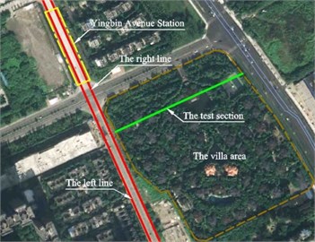
The reason why the test site was selected between Chadianzi Bus Terminal and Yingbin Avenue Station in Chengdu Metro line 2# is that there is a high-grade villa area, in which the price of each villa has been more than 5 million dollars, adjacent to subway lines (see Fig. 1) and subjected to subway vibration. The shortest distance between villas and the center of the test subway line is about 20 m, so the vibration and noise induced by subway had seriously influenced the normal life of the residents in these villas before adoption of control measures. In order for a complete solution of the problem, it was suggested to replace the common rail fasteners with rail suspension fasteners.
Fig. 1The surroundings of the testing site (Source: http://www.amap.com)
2.1. Chengdu metro line 2#
At present, there are only two operating subway lines in Chengdu. Chengdu Metro line 2# began in service on September 16, 2012. There are 32 Stations in Chengdu Metro line 2# from the southeast to the northwest, which total operating mileage has been up to 44 km.
2.1.1. Vehicle and track
There are three types of subway vehicles in China, named as “Type A”, “Type B” and “Type C”. In Chengdu Metro line 1# and 2#, the operating train consists of 6 “Type B” vehicles with the highest speed of 80 km/h and the maximal axle load of 14 t, in which there are 4 motor vehicles and 2 trailers. The size of a “Type B” vehicle is 19 m×2.8 m×3.8 m, which bogie interval, wheelbase and wheel diameter are 12.6 m, 2.2 m and 0.84 m, respectively. Additionally, the detailed mechanical parameters of “Type B” vehicles are listed in Table 1. In Table 1, , and denote the mass of car body, bogie frame and wheelset; and are the moment of inertia of car body and bogie; and are the stiffness and damping of the primary suspension of the train; and are the stiffness and damping of the secondary suspension.
Table 1Inertial characteristics and suspension parameters of Chinese “Type B” vehicle
Car type | (kg) | (kg) | (kg) | (kg·m2) | (kg·m2) | (N/m) | (N·s/m) | (N/m) | (N·s/m) |
“Type B” car | 39540 | 3520 | 1539 | 1.328×10⁶ | 1.76×10³ | 1.7×10⁶ | 6.0×10⁴ | 4.5×10⁵ | 6.0×10⁴ |
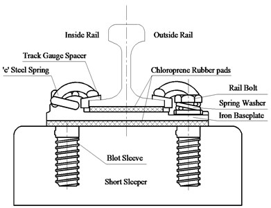
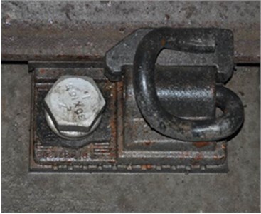
Fig. 2The detail structural components of DZ III rail fastener
a)
b)
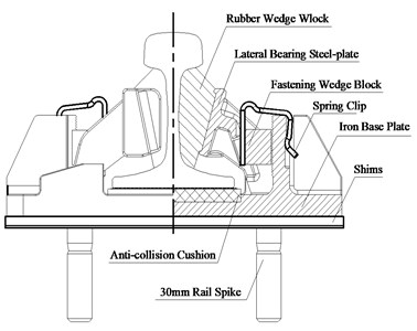
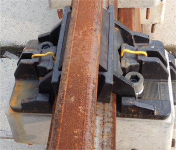
Fig. 3The detail structural components of rail suspension fastener
a)
b)
Before replacement of common rail fasteners, the track structure of the test subway line is made up of 60 kg/m rail, DZ III rail fasteners, and the short sleeper buried in the non-ballast bed. DZ III rail fastener is composed of “e” steel spring, track gauge spacer, bolt, gauge-adjusting clip, iron baseplate, chloroprene rubber pads under rail and iron baseplate, shims and bolt sleeve (Fig. 2). The vertical static stiffness of DZ III rail fastener at a supporting position is 30-35 kN/mm, and the ratio between its dynamic stiffness and its static stiffness is less than 1.4. Its gauge-adjusting space is –12-+10 mm. Its adjustable height is 0-+30 mm.
As shown in Fig. 3, rail suspension fastener at a supporting point is composed of rubber wedge block (natural rubber), lateral bearing steel-plate, fastening wedge block (natural rubber), spring clip, iron base plate, shims, rail spike with the diameter of 30 mm, anti-collision cushion (natural rubber or polyester rubber). It is provided with the adjustable gauge of –5-+5 mm and the adjustable height of 0-+30 mm. In the test, the vertical static stiffness of rail suspension fastener at a bearing point is only 5-8 kN/mm. In order to make an excellent join between the common and the rail suspension fasteners, it is necessary to design a 5 or 10 m long transition in which the vertical static stiffness of rail suspension fastener is 14-18 kN/mm.
It is noting that rail suspension fastener, different from most of ordinary rail fasteners, has a unique construction. The rail base of rail suspension fastener with rail waist elastically fastened is suspended over anti-collision cushion, while the rail base of ordinary rail fastener is elastically fastened on the sleeper. Thus, the unique construction of rail suspension fastener allows the lower rail-supporting stiffness so as to improve the vibration-reduction effect. For further improvement of the vibration-attenuating effect of rail suspension fastener, a new optimizing approach is to add a tuned damper into the rubber wedge block of rail suspension fastener. In this test study, only the ordinary rail suspension fasteners were used.
2.1.2. Tunnel and soil layers
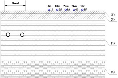
The tunnel of the test subway is shield tunnel with the outer diameter of 6.2 m and the buried depth of about 10.5 m. The net spacing distance between two parallel subway lines is 6.8 m. The test site is a four-layer structure. Their basic physical and mechanical parameters are listed in Table 2.
Table 2Basic physical and mechanical parameters of foundation soil in test site
Soil layer | Soil type | Thickness (m) | Dynamic Young’s modulus (MPa) | Dynamic Poisson ratio | Damping ratio | Density (kg/m3) | Shear wave velocity (m/s) |
(1) | Q4ml clay | 1.23 | 110.6 | 0.36 | 0.030 | 1755 | 155 |
(2) | Q4al slity clay | 2.81 | 276.1 | 0.37 | 0.030 | 2020 | 231 |
(3) | Q4al silt and medium sand | 19.7 | 202.2 | 0.38 | 0.034 | 1979 | 211 |
(4) | Q3fgl+al cobblestone | Over 20 | 579.8 | 0.37 | 0.028 | 2397 | 326 |
2.2. Test scheme
In order for contrast of the vibration-control effect between DZ III rail fasteners and rail suspension fasteners in both time and frequency domains, vertical ground vibration accelerations of 5 measuring points (Fig. 4) in the test section (Fig. 1) were captured before and after replacement of common rail fasteners. The first test was performed in April 2014, in which there were a total of 6 groups of measured ground vibration data induced by the right subway line. After that, DZ III rail fasteners in both right and left subway lines were replaced by rail suspension fasteners in May 2014. One year later, the second test was carried out in May 2015, similarly a total of 6 groups of measured ground vibration data caused by the right subway line were collected again at the same positions.
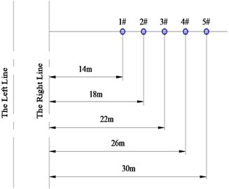
Fig. 4a) The top view and b) the cross-section view of measuring point arrangement
a)
b)
2.2.1. Arrangement of measuring points
Because of the prohibition for arrangement of measuring points on the road pavement (see Fig. 1), there were 5 testing points arranged at intervals of 4 m within the range of 30 m from the subway centerline, as shown in Fig. 4. They were at a distance of 14 m, 18 m, 22 m, 26 m and 30 m from the track centerline of the right subway line, respectively.
2.2.2. Test instruments
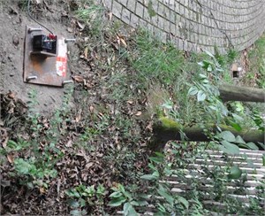
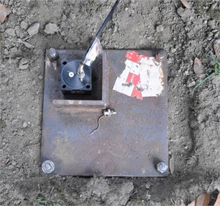
The vibration acceleration sensors were installed on a 21 cm×21 cm×1 cm steel plate fixed to the ground in the test section (Fig. 5). The measurement range, the effective frequency range and the sensitivity of the vibration sensors are 0-2 g, 0.25-80 Hz and 0.31 V·s2/m respectively.
The signal-collecting instrument supplied by Integrated Measurement & Control was applied to record ground vibration caused by each passing train. Each sampling time was no less than 20 s which was long enough to capture a whole train passage with speed 45-50 km/h. Its sampling frequency is 2000 Hz.
Fig. 5The vibration acceleration sensors in this field test
a)
b)
3. Analysis of in-situ testing results
Six groups of the vertical ground vibration accelerations at each testing position are compared between before and after replacing rail fasteners in both time and frequency domains. Firstly, six groups of the time-domain peak particle accelerations (PPAs, unit: m/s2) at each measuring location before and after adoption of rail suspension fasteners are summarized for analysis of the time-domain vibration-reduction effect of rail suspension fasteners; meanwhile, the variations of their PPAs with the distance to subway centerline are also discussed. Secondly, according to the frequency-weighted method used to evaluate the influence of vertical ground vibration accelerations on the stand-up human body in ISO2631-1-1997, the measured time-domain data are converted into 1/3 octave frequency-weighted vibration acceleration levels (VALs, unit: dB) so as to explore the frequency-domain vibration-attenuating effect of rail suspension fasteners. Finally, the integrated VLzs (unit: dB) in 1/3 octave center frequencies of 1-125 Hz at each measuring point are calculated to investigate the comprehensive vibration-alleviating effect of rail suspension fasteners.
3.1. Time-domain analysis
3.1.1. Time-domain peak particle acceleration (PPA)
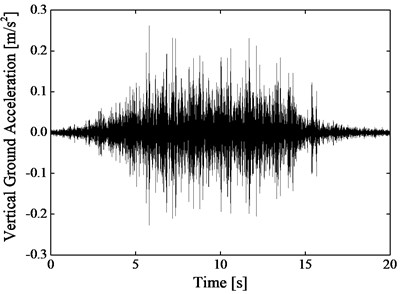
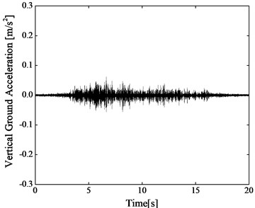
Using one of six measured cases at the measuring point 1# as an example, the difference of the time-domain vertical ground vibration accelerations induced by subway between before and after replacement of rail fasteners is given in Fig. 6. Fig. 6(a) and 6(b) are before and after application of rail suspension fasteners, respectively.
It is found from Fig. 6(a) that the periodic vibration clusters can be recognized in the time-domain vertical ground vibration acceleration at the measuring position 1# before replacement of common rail fasteners. However, after application of rail suspension fasteners, it is very difficult to discriminate the moment when each vehicle passes by the measuring section. Overall, after DZ III rail fasteners are replaced by rail suspension fasteners, the time-domain vertical ground vibration accelerations would transform from the concentrated vibrations to the decentralized ones, as shown in Fig. 6(b). Besides, the PPA at the testing point 1# after adoption of rail suspension fasteners is about 20 % of the PPA at the same location before replacement of rail fasteners.
Fig. 6Time-domain vertical ground accelerations due to subway at the measuring position 1#, which is one of six measured cases a) before and b) after adoption of rail suspension fasteners, respectively
a)
b)
In order for further statistical analysis of the time-domain vibration-reducing effect of rail suspension fasteners, the PPAs of all 6 measured cases at every measuring position are listed in Table 3. These statistical results demonstrate that the decreasing extent of the PPAs at the different locations after replacing rail fasteners is also different. In Table 3, the average PPAs of all 6 measured cases at the testing point 1#, 2#, 3#, 4# and 5# after application of rail suspension fasteners are 22.8 %, 18.6 %, 12.2 %, 49.5 % and 43.1 % of the corresponding average PPAs before replacement of common rail fasteners, respectively. Thus, there is the more significant vibration-isolation effect of rail suspension fasteners on the PPAs at the nearer positions than at the farther ones.
Table 3Six groups of the PPAs (unit: m/s2) at every measuring position before and after replacing common rail fasteners with rail suspension fasteners
Case | 1# | 2# | 3# | 4# | 5# | |||||
B. R. | A. R. | B. R. | A. R. | B. R. | A. R. | B. R. | A. R. | B. R. | A. R. | |
1 | 0.26 | 0.062 | 0.18 | 0.033 | 0.15 | 0.021 | 0.071 | 0.039 | 0.11 | 0.047 |
2 | 0.27 | 0.054 | 0.17 | 0.032 | 0.15 | 0.019 | 0.070 | 0.039 | 0.12 | 0.056 |
3 | 0.26 | 0.062 | 0.17 | 0.033 | 0.16 | 0.019 | 0.077 | 0.039 | 0.11 | 0.050 |
4 | 0.27 | 0.054 | 0.22 | 0.031 | 0.16 | 0.019 | 0.078 | 0.039 | 0.11 | 0.052 |
5 | 0.24 | 0.058 | 0.18 | 0.039 | 0.16 | 0.018 | 0.079 | 0.033 | 0.11 | 0.043 |
6 | 0.25 | 0.064 | 0.16 | 0.033 | 0.16 | 0.019 | 0.078 | 0.035 | 0.12 | 0.045 |
Notes: B. R. and A. R. represent before and after replacement of rail fasteners, respectively | ||||||||||
3.1.2. Variation of PPA with distance to subway centerline
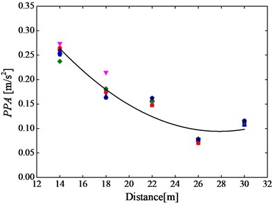
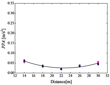
It is also very interesting to investigate the variation of PPA with distance from subway centerline before and after replacement of DZ III rail fasteners with rail suspension fasteners. Fig. 7(a) and 7(b) show that the PPAs of all 6 measuring cases at each measuring point before and after adoption of rail suspension fasteners, respectively.
Fig. 7Six groups (pink downward triangle, red circle, blue triangle, deep blue pentagon and green rhombus) of the PPAs caused by a) DZ III rail fasteners and b) rail suspension fasteners at all 5 test positions
a)
b)
It is found from Fig. 7 that the variation of PPA with distance from subway centerline is apparently different between before and after application of rail suspension fasteners. It can be observed from Fig. 7(a) that the PPAs monotonously decrease with distance increasing from the maximum PPA of 0.27 m/s2 to the minimum one of 0.07 m/s2 before replacement of common rail fasteners. However, after adoption of rail suspension fasteners, it seems that the PPAs are basically framed between 0.06 m/s2 and 0.02 m/s2 with little attenuation, as shown in Fig. 7(b). Besides, it is clear that the minimum PPA due to DZ III rail fasteners is still higher than the maximum one generated by rail suspension fasteners.
3.2. Frequency-domain analysis
It is well-known that subway environment vibration mainly originates from the quasi-static and dynamic loads of vehicle-track coupled interaction in frequency range. As a result, the frequency-domain analysis is necessary for investigation into the effect of rail suspension fasteners on the quasi-static and dynamic vibrations.
3.2.1. 1/3 octave vertical frequency-weighted vibration acceleration level (VAL)
VAL (unit: dB) can be calculated by Eq. (1). In this equation, a represents the vertical frequency-weighted equivalent vibration acceleration (unit: m/s2) in 1/3 octave center frequency, which is the root-mean-square (RMS) of all vibration accelerations at the sampling frequencies in 1/3 octave center frequency band; and is the referenced acceleration (unit: m/s2) which is generally 10-6 m/s2:
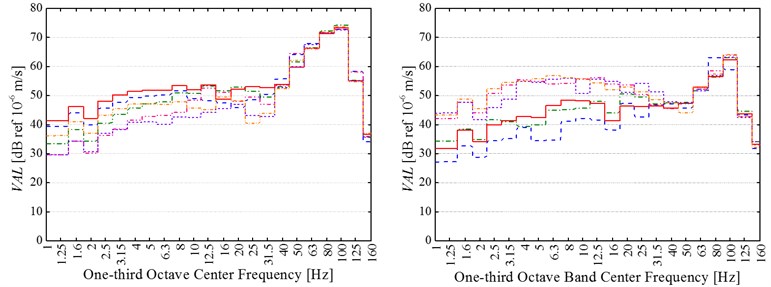
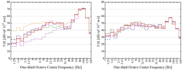
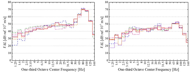
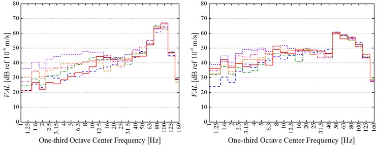
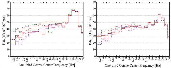
Fig. 8 shows 1/3 octave vertical frequency-weighted vibration acceleration levels (VALs) of all 6 measured cases at every test position before and after replacing common rail fasteners.
Fig. 81/3 octave vertical frequency-weighted vibration acceleration levels (VALs) of all 6 measured cases at the testing positions a) 14 m, b) 18 m, c) 22 m, d) 26 m and e) 30 m to subway centerline before (at left) and after (at right) replacement of common rail fasteners
a)
b)
c)
d)
e)
It can be firstly observed that there is a clear similarity between before and after replacing common rail fasteners about the frequency-distribution characteristics of ground vibration acceleration. The similarity is that all vertical frequency-weighted vibration acceleration levels (VALs) in 1/3 octave center frequencies from 50 to 125 Hz are dominate, and the difference of these VALs in the prominent center frequency bands of 50-125 Hz among six measured cases is small at the same position. However, the difference of these VALs in 1/3 octave center frequencies from 1 to 40 Hz among six measured cases is very conspicuous at each test point. It is because of the different quasi-static excitation induced by the different number of passengers.
Additionally, the vibration-attenuation effect of rail suspension fasteners is more remarkable in 1/3 octave center frequencies between 50 and 125 Hz than in 1/3 octave center frequencies from 1 to 40 Hz. Furthermore, all VALs in 1/3 octave center frequencies of 1~40 Hz universally appears between 20 and 60 dB at each test points both before and after replacing common rail fasteners. According to the previous experience, if the frequency-weighted method in ISO2631-1-1997 is applied, the VALs less than 65 dB are very difficult to be felt by human body. Thus, these VALs in 1/3 octave center frequencies between 1 and 40 Hz have little effect on people’s normal life even if any additional vibration-alleviation measures are not adopted. However, the VALs in 1/3 octave center frequencies of 50-125 Hz should be paid more attention.
In order to show the vibration-attenuation effect of rail suspension fasteners in the dominant 1/3 octave center frequencies of 50-125 Hz, the maximum VAL (VALmax) in 1/3 octave center frequency bands is analyzed. The difference between the lowest (highest) VALmaxin six measured cases at every testing position before replacement of common rail fasteners and the highest (lowest) VALmaxin six measured cases at the same position after application of rail suspension fasteners is calculated. According to the calculated results, the VALmax at the measuring position 1# (2#, 3#, 4# and 5#) decreases by 8.7-11.9 dB (12.4-14.4 dB, 16.8-21 dB, 2.7-7.6 dB and 5.2-10.0 dB) after adoption of rail suspension fasteners. Therefore, rail suspension fasteners mainly reduce the high-frequency dynamic vibration generated by track irregularity or wheel polygon, and yet have little effect on the low-frequency quasi-static vibration.
3.2.2. Variation of the integrated VLz with distance to subway centerline
VLz can be calculated by Eq. (2). In this equation, is still the referenced acceleration (generally 10-6 m/s2), is the RMS of the vertical frequency-weighted equivalent vibration accelerations in all center frequencies:
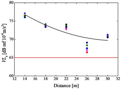
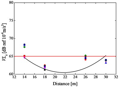
Fig. 9 shows the integrated VLzs at every testing position before and after replacing common rail fasteners. The integrated VLz is enough to be calculated in the center frequencies from 1 to 125 Hz, since the center frequencies of 50-125 Hz are prominent (Fig. 8).
Fig. 9Six groups (pink downward triangle, red circle, blue triangle, deep blue pentagon and green rhombus) of the integrated VLzscalculated in 1/3 octave center frequencies of 1-125 Hz at every testing position a) before and b) after replacing common rail fasteners
a)
b)
As shown in Fig. 9, it is apparently indicated that the variation of VLz with distance from subway centerline is very similar to the variation of PPA with distance. It can be concluded from Fig. 9(a) that these VLzs monotonously decrease with the increase of distance from the maximum of 77.1 dB to the minimum of 66.5 dB, evidently higher than the threshold (65 dB) of the special residential area in Standard of Environmental Vibration in Urban Area of China (G10070-1988), before replacement of DZ III rail fasteners with rail suspension fasteners. However, these VLzs are basically framed between 68.3 and 57.3 dB after application of rail suspension fasteners, most of which are less than 65 dB as shown in Fig. 9(b).
4. Conclusions and suggestions
With the purpose of investigation into the vibration-isolation effect of rail suspension fasteners on environment vibration caused by subway in the time and frequency domains, a field experiment was performed between Chadianzi Bus Terminal and Yingbin Avenue Station in Chengdu Metro line 2#. Firstly, the time-domain peak particle accelerations (PPAs) are compared between before and after replacement of common rail fasteners. Secondly, according to the frequency-weighted method in ISO2631-1-1997, 1/3 octave vertical frequency-weighted vibration acceleration levels (VALs) are calculated so as to explore the vibration-attenuating effect of rail suspension fasteners in frequency bands. Finally, the integrated VLzs in 1/3 octave center frequencies of 1-125 Hz are further discussed and contrasted with the threshold of the special residential area in Standard of Environmental Vibration in Urban Area of China (G10070-1988). The important conclusions and constructive suggestions in this paper are as following.
1) After application of rail suspension fasteners, the time-domain vertical ground vibration accelerations become the decentralized and uniform vibrations, obviously different from several concentrated ones generated by the common rail fasteners. Further through a statistical analysis, it can be found that rail suspension fasteners have more significant vibration-reduction effect on the PPAs at the nearer positions than at the farther ones.
2) The PPAs monotonously decrease with distance increasing before replacement of common rail fasteners, while they slowly reduce with the increase of distance after replacement of common rail fasteners with rail suspension fasteners. Nevertheless, the minimum PPA induced by common rail fasteners is still higher than the maximal PPA caused by rail suspension fasteners at all measuring positions.
3) The vibration-attenuation effect of rail suspension fasteners on ground vibration due to subway is more remarkable in the dominate 1/3 octave center frequencies of 50-125 Hz than in the non-dominate ones of 1-40 Hz. The maximum VAL (VALmax) in the dominate 1/3 octave center frequencies of 50-125 Hz at all measuring positions decrease by 8.7-21 dB after adoption of rail suspension fasteners.
4) The integrated VLzs in 1/3 octave center frequencies between 1 and 125 Hz at all measuring positions show the variation of VLzs with distance to subway centerline is similar to the variation of PPAs with distance. In addition, the integrated VLzs ranged from 77.1 dB to 66.5 dB are higher than the threshold (65 dB) of the special residential area in Standard of Environmental Vibration in Urban Area of China (G10070-1988) before replacement of common rail fasteners. However, after application of rail suspension fasteners, most of the integrated VLzs framed between 68.3 and 57.3 dB are less than the threshold (65 dB).
References
-
Xia H., Chen J. G., Xia C. Y., Inoue H., Zenda Y., Qi L. An experimental study of train-induced structural and environmental vibrations of a rail transit elevated bridge with ladder tracks. Proceedings of the Institution of Mechanical Engineers, Part F, Journal of Rail and Rapid Transit, Vol. 224, Issue 3, 2010, p. 115-124.
-
Fernández P. M., Sanchís I. V., Rojas F. B., Franco R. I. Monitoring and analysis of vibration transmission for various track typologies. A case study. Transportation Research Part D, Vol. 24, 2013, p. 98-109.
-
Hui C. K., Ng C. F. The effects of floating slab bending resonances on the vibration isolation of rail viaduct. Applied Acoustics, Vol. 70, Issue 6, 2009, p. 830-844.
-
Saurenman H., Phillips J. In-service teats of the effectiveness of vibration control measures on the BART rail transit system. Journal of Sound and Vibration, Vol. 293, Issues 3-5, 2006, p. 888-900.
-
Sanayei M., Maurya P., Moore J. A. Measurement of building foundation and ground-borne vibrations due to surface trains and subways. Engineering Structures, Vol. 53, 2013, p. 102-111.
-
Auersch L. The excitation of ground vibration by rail traffic: theory of vehicle-track-soil interaction and measurements on high-speed lines. Journal of Sound and Vibration, Vol. 284, Issues 1-2, 2005, p. 103-132.
-
Kouroussis G., Verlinden O., Conti C. Free field vibrations caused by high-speed lines: Measurement and time domain simulation. Soil Dynamics and Earthquake Engineering, Vol. 31, Issue 4, 2011, p. 692-707.
-
Costa P. A., Calçada R., Cardoso A. S. Track-ground vibrations induced by railway traffic: in-situ measurements and validation of a 2.5D FEM-BEM model. Soil Dynamics and Earthquake Engineering, Vol. 32, Issue 1, 2012, p. 111-128.
-
Zhai W. M., Wei K., Song X. l., Shao M. H. Experimental investigation into ground vibrations induced by very high speed trains on a non-ballasted track. Soil Dynamics and Earthquake Engineering, Vol. 72, 2015, p. 24-36.
-
Connolly D. P., Costa P. A., Kouroussis G., Galvin P., Woodward P. K., Laghrouche O. Large scale international testing of railway ground vibrations. Soil Dynamics and Earthquake Engineering, Vol. 71, 2015, p. 1-12.
-
Gupta S., Liu W. F., Degrande G., Lombaert G., Liu W. N. Prediction of vibrations induced by underground railway traffic in Beijing. Journal of Sound and Vibration, Vol. 310, Issue 3, 2008, p. 608-630.
-
Galvín P., Romero A., Domínguez J. Fully three-dimensional analysis of high-speed train-track-soil-structure dynamic interaction. Journal of Sound and Vibration, Vol. 329, Issue 24, 2010, p. 5147-5163.
-
Connolly D., Giannopoulos A., Forde M. C. Numerical modelling of ground borne vibrations from high speed rail lines on embankments. Soil Dynamics and Earthquake Engineering, Vol. 46, 2013, p. 13-19.
-
Kouroussis G., Florentin J., Verlinden O. Ground vibration induced by InterCity/InterRegion trains: a numerical prediction based on the multibody/finite element modelling approach. Journal of Vibration and Control, 2015.
-
Ferreira P. A., López-Pita A. Numerical modelling of high speed train/track system for the reduction of vibration levels and maintenance needs of railway track. Construction and Building Materials, Vol. 79, 2015, p. 14-21.
-
Hung H. H., Chen G. H., Yang Y. B. Effect of railway roughness on soil vibration due to moving trains by 2.5D finite/infinite element approach. Engineering Structures, Vol. 57, 2013, p. 254-266.
-
Bian X. C., Jiang H. G., Chang C., Hu J., Chen Y. M. Track and ground vibration generated by high-speed train running on ballastless railway with excitation of vertical track irregularities. Soil Dynamics and Earthquake Engineering, Vol. 76, 2015, p. 29-43.
-
Maes J., Sol H., Guillaume P. Measurements of the dynamic railpad properties. Journal of Sound and Vibration, Vol. 293, Issues 3-5, 2006, p. 557-565.
-
Carrascal I. A., Casado J. A., Polanco J. A., Gutiérrez-Solana F. Dynamic behavior of railway fastening setting pads. Engineering Failure Analysis, Vol. 14, Issue 2, 2007, p. 364-373.
-
Luo Y., Liu Y., Yin H. P. Numerical investigation of nonlinear of properties of a rubber absorber in rail fastening systems. International Journal of Mechanical Sciences, Vol. 69, 2013, p. 107-113.
-
Li W. X., Dwight R. A., Zhang T. L. On the study of vibration of a supported railway rail using the semi-analytical finite element method. Journal of Sound and Vibration, Vol. 345, 2015, p. 121-145.
Cited by
About this article

This research was supported by National Natural Science Foundation of China (Grant No. 51578468), Fundamental Research Funds for the Central Universities of China (Grant No. 2682015CX087), National Outstanding Youth Science Foundation of China (Grant No. 51425804), Joint Funds from both Chinese High-speed Railway Company and the National Natural Science Foundation of China (Grant No. U1234201 and U1434201), Open Foundation supplied by State Key Laboratory for Track Technology of High-speed Railway in China Academy of Railway Sciences (Contract No. 2015YJ005).
