Abstract
The article deals with the creation of a generalized mathematical model of inclinometer that allows more fully than any known prior mathematical model to study its properties under actual operating conditions. The mathematical model of inclinometer considered non-identical electrical parameters of the primary sensors. Mathematical model of a linear single-axis accelerometer is also built, which is part of the inclinometer.
1. Introduction and motivation
Inclinometer is a very complicated electromechanical system functioning under the influence of a greater number of influencing factors [1]. Analysis of the requirements for bottom-hole information-measuring system (IMS) for a known length of the trajectory of the well showed that the basis for the construction of directional navigation sensors must be based on information about the spatial rotation of the drilling tool relative to the two non-collinear vectors. The basis of such vectors relies vector acceleration of gravity , magnetic field vector and the vector of the Earth Earth’s angular velocity . This proved that the measurement of two collinear vectors are sufficient to determine the mobile system with respect to the base.
To compile mathematical models inclinometer responding to vectors of any physical nature, introduced in consideration of the right of the coordinate system (Figs. 1-2).
Fig. 1The schematic diagram of coordinate systems
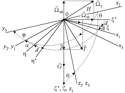
Figs. 1, 2 introduced the notation: – fixed frame corresponding to the geographic coordinate system , it axis tangential to the meridian and the geographic North, axis – tangential to the parallels and the East; axis – the vertical space and deep into the earth. Frame R corresponds trihedral coordinate system in which the axis is directed along the magnetic meridian, the axis – the vertical space and down, axis perpendicular to the axis of , axes, and thus to get a trihedron was right. Trihedron of coordinates is rotated relative to the angle of magnetic declination; coordinate system associated with the plane of the borehole inclination, the axis of which lies in a horizontal plane and coincides with the projection of the hole axis on a horizontal plane. Regulations define downhole plane azimuth true or magnetic, counted, respectively, from the northern areas of geographical or magnetic meridian. The plane is called the plane of inclination of the well, the well plane curvature, or apsidal plane; coordinate system associated with the hole inclination axis, which is directed along the tangent to the trajectory of the axis of the axis at the point , then the angle is the zenith angle – the angle deviation of the borehole axis from the vertical; coordinate system associated with the tubular string. Trihedron axes obtained from the initial rotation about the axis by an angle called reticle (apsidal angle whipstock angle drilling tool) [2].
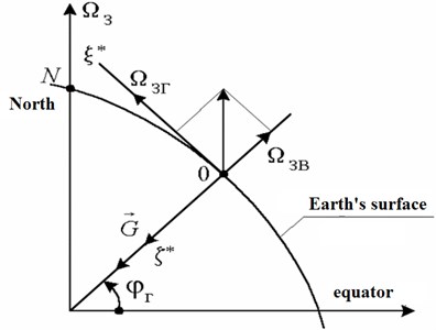
Fig. 2The projections of the angular velocity of the Earth rotation axes associated with the wellhead
2. The model of the system
The projections of the vectors of the magnetic field of the Earth (MFE) , Earth’s angular velocity , acceleration of gravity on the axis , of the frame, will be:
where , – latitude and angle of magnetic inclination; , – horizontal and vertical components of the magnetic field of the Earth. Let:
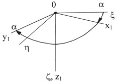
The transition from a fixed reference point , associated with the Earth, to the moving frame associated with the column of pipes, by successive rotation through the final , , , corresponding to Euler angles (Fig. 3).
Fig. 3Consecutive transitions from the fixed bound Earth coordinate system 0ξηξ to the mobile 0x3y3z3
a)
b)
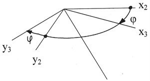
c)
Coordinate systems and related by the formula:
where , , – the components of a vector in the frame ; – components of the vector in the frame , – the matrix of the direction cosines between the rapper and found as the product of the matrix between the intermediate axes.
The expressions for the projection of the magnetic field of the Earth , the angular velocity of the Earth rotation in inertial space and the vector acceleration of gravity (or gravity) in the fixed system of coordinates on the axis associated with the downhole projectile collinear axis of the frame :
This chapter offered generalized mathematical models inclinometer with the three still enshrined in the well projectile primary sensors, which are obtained by the design of vectors , , on the sensitivity axis of the magnetic, gyroscopic angular velocity sensors (AVS) and accelerometers, which form the basis of the structure of the inclinometer:
where – the matrix of the direction cosines between the axes of the frames , , .
Between these equations there are six ratios:
expressing the fact that the orthogonal transformation units projected vectors and their scalar products in the original and projected coordinate systems are the same.
The set of Eqs. (1)-(3) is a generalized mathematical model in matrix-vector form gyromagnetic inclinometer with fixedly mounted in a downhole projectile uniaxial magnetic, gravity and gyroscopic sensors primary. From it derived the mathematical models only magnetic (flux-gate), only the gyroscopic inclinometer or just gravity. By solving the Eq. (1) with respect to the desired coordinates , , , calculated angular parameters of the spatial orientation of the underground mobile device.
The mathematical model of inclinometer considered non-identical electrical parameters of the primary sensors. For uniaxial primary sensors inclinometers (ferroprobes, accelerometer, gyroscopic AVS) output signal can be written as [3]:
where , , – the highest values ferroprobes output signal AVS gyro, accelerometer, and , , – zero signal sensors, , , , 1, 2, 3 – the direction cosines between the vectors , , and the sensitivity axes of the primary sensor on the assumption that the sensitivity axis of the primary sensors collinear axis of the frame .
Then the calculation of the primary sensor signal with respect to their non-identical electrical parameters is carried out by the formulas:
Eqs. (4)-(6) are a mathematical model of information signals from the transmitters.
The mathematical model inclinometers also take into account the angular misalignment of the primary sensor in the coordinate system associated with the housing as the base surface of the primary sensors are generally not coincide with their sensitivity axes, besides the seats beneath them in the housing inclinometer fulfilled with limited accuracy due to variation of parameters of technological processes of production of components and assembly. Therefore, the model must take into account fully the connection between the sensor signals and the components of vector fields , .
Denoting – guides the unit vectors of the axes of sensitivity -th primary sensor 1, 2, 3, for example, ferroprobe:
we obtain the projection of the vector where , , – unit vectors orthogonal axes as the:
Consequently, the output signals from primary sensors can be represented as:
Systems of Eq. (7), are the primary scalar equations relating the testimony imperfect ferroprobe with an error of inclinometer casing installation.
Designed inclinometers include accelerometers in its design. They reviewed the working principles drawn up its mathematical model investigated the error of the base vibration, and also shows the possibility of creating vibration and vibration inclinometers [3].
With the help of three accelerometers measured the three projections of the vector acceleration of gravity on the sensitivity axis accelerometers, which are functionally linked with the desired zenith and reticle angles.
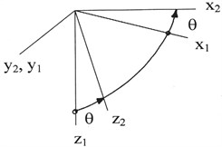
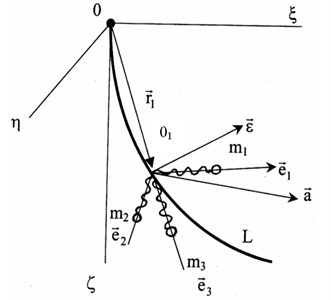
Mathematical model of single-axis linear accelerometer includes a mass inertial element , its movement (1, 2, 3). Let inclinometer comprising three uniaxial linear accelerometer sensitive axes are mutually orthogonal , , , is moved along a curve representing the trajectory of the well (Fig. 4). At the same time it moves with linear and angular accelerations , . The accelerometer is shown as a mass on a spring. The equation of motion of the inertial element accelerometer in general terms is as follows : where – the tension “electric” spring rate ; – the equilibrium position in the absence of acceleration ; – communication reaction rail axis .
The absolute acceleration of the motion th inertial body made up of the acceleration of the portable motion (movement along the curve and the rotation of the unit vector ), the acceleration of the relative movement (movement along the rail axis ) and the Coriolis acceleration :
The accelerations and velocities of inertial motion of the body are of the form:
where , – angular velocity and acceleration of the point . After the transformation of the original equation takes the final form:
which is a generalized mathematical model of the accelerator, moving along an arbitrary curve .
Fig. 4Explanation of the mathematical model of the accelerometer
3. Conclusions
It was found that the measurement of the two non-collinear vectors sufficient to determine the orientation of the moving coordinate system relative to the base (fixed) associated with the Earth. The basis of the construction of directional sensors on information about the spatial rotation of the drilling tool with respect to any two non-collinear vectors ta-cal as vector acceleration of gravity vector of the Earth’s magnetic field vector and the Earth’s angular velocity.
Made a significant contribution to the development of the theory of directional transducers is to obtain a generalized mathematical model in matrix-vector form gyromagnetic inclinometer with fixedly mounted in a downhole projectile magnetic, gyroscopic, and gravity sensors, which allows to obtain mathematical models only magnetic (flux-gate), only gyro, or only gravity (to determine a position diverter and zenith angle of inclination) inclinometers.
References
-
Isachenko W. H. Well Inclinometer. Nedra, 1987, p. 216, (in Russian).
-
Kovshov G. N., Kolovertnov G. Y. Navigation devices and inclinometer spatial orientation sensors control the drilling tool when drilling. Proceedings of the International Conference on “Methods, Tools and Technologies of Reception and Processing of the Measuring Information”, 2000, p. 105-106, (in Russian).
-
Krasnov A. N., Ishinbaev N. A., Kolovertnov G. Y. Measuring channels for use with piezoresistive sensors. Materials of the 11th Scientific-Technical Conference “Sensors and Transducers Information Systems for Measuring, Monitoring and Control”, 1999, p. 140-141, (in Russian).
-
Avery T. E., Burkhart H. E. Height Measurement Principles. Forest Measurements (5th ed.). McGraw-Hill, 2002, p. 154.
-
Williams M. S., Bechtold M. A., LaBau V. J. Five instruments for measuring tree heights: an evaluation. Southern Journal of Applied Forestry, 1994, p. 76-82.
About this article

