Abstract
Structural vibration includes both translational and rotational degrees of freedom, but the latter are often ignored. The paper establishes a dynamic inclination measurement model based on the existing accelerometer, and constructs state and measurement equations that comprehensively represent translational and rotational degrees of freedom. Then, the extended Kalman filtering method is used to linearize and discretize the state equation and measurement equation, and the filtering process of dynamic Inclination Identification is derived. The feasibility of the method was verified through an example of a simply supported beam structure.
Highlights
- Establish a measurement model for dynamic inclination based on acceleration and extended Kalman filtering method
- Establish state and measurement equations representing translational and rotational degrees of freedom
- Estimate the dynamic changes in inclination of the sensor installation position from the measured values of translational acceleration
1. Introduction
Vibration is the general state of structures in nature. Through vibration observation, the state of structures can be seen, predicted, and controlled [1]. In addition to monitoring the dynamic characteristics of structures, another important value of structural vibration monitoring is to identify the attitude of the structure [2-4], including the translational and rotational deformation. When accelerometers are used for structural vibration monitoring, the monitored data is essentially composed of gravity acceleration on the sensor measurement axis and the incremental information of the structure under external loads.
By the proportional relationship between the monitoring data and the gravity acceleration, the tilt data of the structure can be obtained, which is the main principle of inclination measurement method in the current engineering community. However, it should be clarified that since the component of gravity acceleration is essentially a static component, this monitoring method can only be used for static inclination monitoring, and cannot be used for real-time monitoring of the dynamic inclination of the structure during high-frequency vibration, making inclination measurement technology unsuitable for dynamic feature diagnosis of structures.
Meanwhile, existing vibration monitoring often does not pay attention to the vibration direction of the structure, and generally only uses the assumed direction as the vibration direction. If the vibration direction of the structure can be considered, the monitoring data can be corrected, and the vibration attitude of the structure can be obtained. Then theoretically, the translational and rotational deformation of the structure in the global coordinate system can be obtained, which can establish an effective solution for the global vibration information of the structure [5].
Based on the above considerations, this paper proposes a method for identifying real-time dynamic inclination angles of structures using extended Kalman filtering (EKF) [6-8] technology. Firstly, we establish a model for structural vibration monitoring, and provide corresponding state vectors; Secondly, based on the EKF method, establish the state equation and measurement equation of the vibration monitoring system, and provide the calculation process of dynamic inclination estimation; Finally, a simulation case is used for validation.
2. Vibration monitoring model
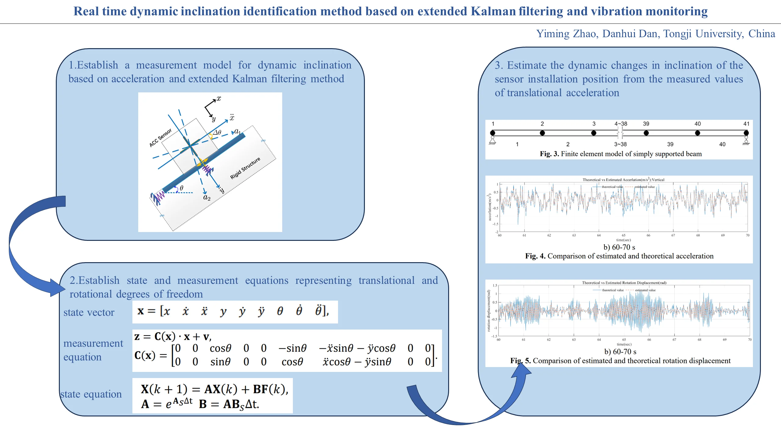
At present, acceleration data is commonly used in engineering to measure inclination angles, which is arccosine value of the ratio of the acceleration data measured on the sensitive axis of the accelerometer to the gravitational acceleration. The specific principle is shown in Fig. 1(a).
Fig. 1Principle of inclination angle calculation
a) Static state
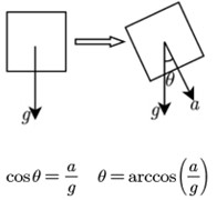
b) Vibrational state
When the structure is in the vibration state, there is additional acceleration information on the sensitive axis of the tilted accelerometer, and this acceleration information is not a component of gravity acceleration, but is caused by structural vibration, shown in Fig. 1(b). Therefore, there will be deviation in the inclination measurement according to the formula in the static state, and the existing inclination measurement technology cannot accurately measure the inclination angle of structure in vibration state.
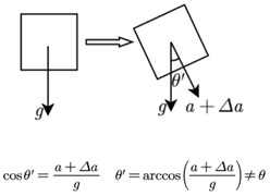
To clarify the relationship between tilt angle vibration and translational vibration, a model was established as shown in Fig. 2. Assuming that the angle between rigid structure and horizontal plane is , and an acceleration sensor is used to monitor the in-plane two-dimensional acceleration of the structure. The monitored accelerations are represented by and respectively, while denotes the tangential values and denotes the normal values. Based on the tangential and normal directions, the standard coordinate system for the vibration response observation of the structural can be established, while represents the tangential standard direction and represents the normal standard direction.
Fig. 2Two-dimensional model for illustration
When the structure undergoes vibration in the standard global coordinate system, there will be vibration in the translational direction as well as vibration in the rotational direction. The rotational vibration is represented by the rotation angle of the sensitive axis of the sensor, which is the dynamic inclination angle. If the dynamic inclination angle is ignored, the acceleration measured by the accelerometer will always undergo a change in direction; In this case, when there is no translational vibration in the structure and only rotational vibration, the acceleration measured by the accelerometer still has a non-zero value, which is only generated by the dynamic inclination angle, such as in a structure that is only in a rotating state.
If the rigid structure rotates with an angle , the sensitive axis of the acceleration sensor will change simultaneously, and the real acceleration measured will change from to , while and have a relationships with plane transformations. In the real world, researchers always mistakenly use the actual measured as , while completely ignoring the impact of the rotation angle.
Based on the above model, considering the plane transformation relationship between and , the solution of and corresponding rotation angle can be obtained from the time domain vlue of . In time-domain estimation methods, the Kalman filter method (KF) [9] is a good algorithm that can achieve tracking of structural vibration states. Therefore, this paper adopts the Kalman filtering method to estimate and calculate the dynamic inclination angle of the structure in real-time.
3. Dynamic inclination estimation method
3.1. State vector
According to the translational and rotational deformation of the aforementioned model, the rigid body composed of the sensor and the base not only has translational degrees of freedom, but also has rotational degrees of freedom in the plane around the center point of the sensor installation base, which can be understood as the swinging of the rigid tangent plane at the boundary surface (curve) point position. In order to characterize these parameters and we need to use motion state variables (such as, , , ) in a global fixed coordinate system to fully describe the vibration of the structure, rather than simply using the values measured. Therefore, the state vector can be represented as shown in the following form:
wherein, is used to represent the displacement, denotes velocity, and is the acceleration; denotes the inclination angle, the angular velocity and the angular acceleration respectively.
3.2. Measurement equation
Under local coordinates which rotates with the structure, the observation values on the two sensitive axes of the bidirectional accelerometer are and , forming the measurement vector , namely:
By utilizing the geometric relationships displayed in the vibration monitoring model, it is easy to write the following measurement Eq. (1):
Thus, the measurement vector and state vector can be represented by following Eq. (4):
wherein, is the measurement noise, , and satisfies:
Furthermore, using the EKF method for linearization, and we can obtain:
3.3. State equation
The dynamic equation for the measured points in the vibration system can be shown in the following Eq. (8):
wherein, , and is the external excitation vector in the two directions of the measured point. , , are respectively the mass matrix, damping matrix and stiffness matrix condensed to the measured point:
Introduce the following auxiliary Eq. (9) shown above, we can get Eq. (10):
It can be further simplified as Eq. (11) and Eq. (12):
Further simplifying Eq. (12), and we obtain Eq. (14):
The Eq. (14) can be solved and discretization to obtain:
Since the external excitation is unknown, but it can be proved that the long-term statistical value of the external excitation conforms to the distribution of Gaussian white noise, therefore, can be regarded as Gaussian white noise , and satisfies:
3.4. Kalman filtering method
According to the EKF method, the estimation process is expressed as follows:
(1) Assuming the initial state vector and initial estimated variance in the initial state , where the initial state vector is represented by and the initial estimated variance is represented by .
(2) Based on the state Eq. (16), perform the step-1 filtering calculation as follows. The load can be treated as noise:
(3) Calculate the estimated variance of the step-1 filtering calculation as follows:
(4) Based on the estimated variance calculated by the step-1 filtering step, combined with the noise variance in the measurement equation and the linearized measurement matrix, the optimal filtering gain matrix is calculated as follows:
(5) Based on the nonlinear measurement equation and the filtering gain matrix, update the filtering estimation to obtain :
(6) Based on the filtering gain matrix, linearized measurement matrix, and estimated variance calculated from the seep-1 filtering step, the step-2 filtering estimation variance matrix is calculated as follows:
(7) Using and as the initial values for the next stage, continue with the next filtering estimation.
4. Numerical simulation research
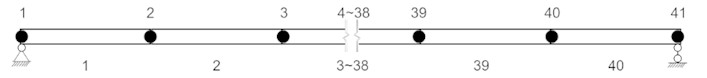
Design a beam model for validation. Assuming a simply supported beam structure with a total length of 80 m, consisting of 40 beam elements, each with a length of 2 m, and consider the rotational and translational degrees of freedom. The number of nodes is 41, and the total number of degrees of freedom is 123. The model is shown in the following Fig. 3. The translational and rotational dynamic response under external excitation can be calculated as the theoretical value.
Fig. 3Finite element model of simply supported beam
Based on the previous derivation process, the measurement equation and state equation of this case are established, the external excitation is treated as the white noise. The comparison curves between vertical acceleration and theoretical values can be solved as shown in Fig. 4. It can be seen that the estimated values are similar to the theoretical values and exhibit similar fluctuation characteristics.
In the Fig. 4, it can be seen that when the inclination angle value is small, the recognition is more accurate, while when the inclination angle suddenly increases, the recognition error is relatively large. The main reason is that there is a certain error between the linearized and nonlinear measurement equations, and the error will be amplified when the inclination angle appears in a larger value area. However, considering that the inclination angle of engineering structure is mainly within a small range, it is estimated that the above results can be accepted in engineering practice.
Fig. 4Comparison of estimated and theoretical acceleration
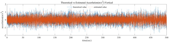
a) 0-500 s
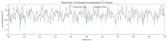
b) 60-70 s
In the Fig. 4, the theoretical acceleration is obtained by solving the dynamic response of the structure under white noise excitation, and the method used is Runge Kutta method; The estimated acceleration is filtered by EKF method under the assumed white noise excitation. It can be seen that the trend between the estimated acceleration and the theoretical value is basically consistent. Therefore, using the EKF filtering method can present a result that the estimated value of acceleration can keep up with the changes in the theoretical value. In addition, there is a small difference in amplitude between the two, which is caused by the error caused by the linearization of the measurement equation during the EKF filtering process. This error can become significant under large inclination angles, and further research is needed. However, it should be clarified that in civil engineering structural monitoring, most monitoring objects are structures with small inclination changes.
By using the EKF method, the comparison between the estimated angle and the theoretical angle can be obtained as shown in the following Fig. 5. It can be seen that the estimated angle values are almost consistent with the theoretical angle in trend, with a certain degree of deviation in amplitude.
Fig. 5Comparison of estimated and theoretical rotation displacement
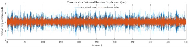
a) 0-500 s
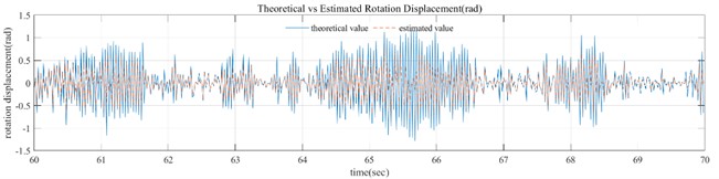
b) 60-70 s
In the Fig. 5, it can be seen that when the inclination angle value is small, the recognition is more accurate, while when the inclination angle suddenly increases, the recognition error is relatively large. The main reason is that there is a certain error between the linearized and nonlinear measurement equations, and the error will be amplified when the inclination angle appears in a larger value area. However, considering that the inclination angle of engineering structure is mainly within a small range, it is estimated that the above results can be accepted in engineering practice.
This paper has not yet carried out strict correlation analysis on the intensity of white noise and the estimated value. For the external white noise signal used, its variance is assumed, and used as the estimated variance to be substituted into the EKF filtering process. It can be imagined that the calculation results will change with the change of noise intensity, but the change should not be significant, which requires research on the statistical characteristics of external excitation. The purpose of this study is that the acceleration and dynamic small tilt angle can be effectively identified when the external white noise estimation is basically accurate. Therefore, based on the external white noise study, the translational acceleration and dynamic tilt angle can be effectively identified.
Furthermore, we can discuss the variance of the excitation white noise used in the filtering process. According to Eq.16, the -th state is obtained from the statistical characteristics of the -th state and the excited white noise, where in represents the attenuation of the -th state, which is caused by damping, similar to the attenuation form of automatic vibration under damped vibration; represents the vibration state response caused by the -th external excitation, which can be understood as the change value of the -th state relative to the -th state caused by external excitation. In the EKF filtering process, the variance of is used when calculating , and can be expressed as . Meanwhile, further affects the filtering gain matrix and the step-2 filtering estimation variance matrix . Therefore, from the perspective of state equation, the variance of white noise in the filtering process will have a greater impact on the filtering calculation results.
However, the advantage of Kalman filters lies in considering both the state equation and the measurement equation. We cannot estimate the white noise of external excitation accurately, but can only estimate a reasonable range; In the process of Kalman filtering, the error caused by the selection of the variance of the externally excited white noise will be corrected by the introduction of the measurement equation, that is, while the estimation variance of the externally excited white noise is given a deviation, the weight of the estimation value of the measurement equation will be increased automatically in the process of calculating the filter gain, so as to achieve higher accuracy. Therefore, the selection of the variance of the excitation white noise has a low impact on the estimation results.
It can also be proven from the calculation results of the dynamic inclination angle that the error of the dynamic inclination angle is relatively large when there is a large angle change, mainly due to the large linearization error of the measurement equatio, rather than due to the state equation. This also shows that the influence of the measurement equation on the estimation accuracy in the whole filtering process is much higher than the error influence caused by the variance of the external white noise. It is feasible in engineering practice to obtain the statistical characteristics of white noise caused by external excitation in a period of time and set a reasonable range. Therefore, the research results in this paper are feasible enough.
5. Conclusions
This paper establishes a vibration monitoring model for dynamic inclination angle recognition, provides measurement equations and state equations based on the extended Kalman filtering method, and provides the entire process of Kalman filtering for real-time dynamic inclination angle recognition. It is verified through a simple supported beam model example, and the results show that the dynamic inclination angle has sufficient recognition accuracy in the small inclination angle range, and compared to existing static inclination measurement methods, it can achieve real-time dynamic measurement of the inclination angle.
References
-
C. P. Fritzen, “Vibration-based structural health monitoring-concepts and applications,” Key Engineering Materials, Vol. 293, pp. 3–20, 2005.
-
C. C. Chang and X. H. Xiao, “Three-dimensional structural translation and rotation measurement using monocular videogrammetry,” Journal of Engineering Mechanics, Vol. 136, No. 7, pp. 840–848, 2010.
-
C. Schmelzbach et al., “Advances in 6C seismology: Applications of combined translational and rotational motion measurements in global and exploration seismology,” Geophysics, Vol. 83, No. 3, pp. WC53–WC69, May 2018, https://doi.org/10.1190/geo2017-0492.1
-
L. Wu, Y. Su, Z. Chen, S. Chen, S. Cheng, and P. Lin, “Six‐degree‐of‐freedom generalized displacements measurement based on binocular vision,” Structural Control and Health Monitoring, Vol. 27, No. 2, 2020.
-
B. Xu, D. Dan, and Y. Zhao, “Frequency-domain estimation method for vibration-induced additional cable tension based on acceleration monitoring,” Journal of Vibration and Acoustics, Vol. 141, No. 6, Dec. 2019, https://doi.org/10.1115/1.4044673
-
M. Hoshiya and E. Saito, “Structural identification by extended Kalman filter,” Journal of Engineering Mechanics, Vol. 110, No. 12, pp. 1757–1770, 1984.
-
J. He, X. Zhang, and B. Xu, “Identification of structural parameters and unknown inputs based on revised observation equation: approach and validation,” International Journal of Structural Stability and Dynamics, Vol. 19, No. 12, p. 1950156, Dec. 2019, https://doi.org/10.1142/s0219455419501566
-
O. Maruyama, M. Shinozuka, and M. K. Daigaku, “Program EXKAL2 for identification of structural dynamic systems,” National Center for Earthquake Engineering Research, 1989.
-
R. E. Kalman, “A new approach to linear filtering and prediction problems,” Journal of Basic Engineering, Vol. 82, No. 1, pp. 35–45, Mar. 1960, https://doi.org/10.1115/1.3662552
About this article

The authors have not disclosed any funding.
The datasets generated during and/or analyzed during the current study are available from the corresponding author on reasonable request.
The authors declare that they have no conflict of interest.
