Abstract
With the development of underground prefabricated building structure, the influence of waterproof performance on underground engineering construction is becoming more and more important. Based on the analysis of the current situation of waterproof technology of prefabricated subway station joints, this paper conducts similar experiments on the waterproof mechanism and construction characteristics of the water-swelling rubber water-stop selected at the joint, and analyzes the waterproof performance of the assembly joint and the overall performance of the structure. It lays the foundation for the selection of waterproof materials, structural size optimization and opening design of the prefabricated subway station structure, and analyzes the waterproof performance of the rubber water-stop. In order to grasp and record the overall stability and waterproof performance of the assembled subway station structure in time, on the basis of field investigation, the model joint specimens of the assembled subway station joints were made according to the similar theoretical model experiment, and the joints of the assembled subway station joints were watered. The internal seepage, development and deformation convergence of the specimen structure were monitored in real time. The monitoring results will provide data support for the operation safety of the assembled subway station.
Highlights
- The research direction of the article is relatively new, starting from the waterproof performance of the annular water stop of the underground assembly structure, the overall stability and waterproof performance of the structure are analyzed, and there are few studies on the waterproof performance of the parts at home and abroad
- The author conducted a full field investigation and proposed a similar theoretical model of the assembled subway station joint, and measured the waterproof performance of the water-stop from the aspects of axial pressure and water pressure to enhance the accuracy of the test
- The model test theory is simple, the test operation is simple, the use of multiple sets of data to reduce the test error, the experimental data processing is more scientific, the difference is clearly visible in the comparison
1. Introduction
The sealing materials mainly used in underground engineering are gradually transformed from early asphalt, elastic foamed rubber, two-component polythioester, two-component polyurethane and other materials [1] to sealing materials based on elastic rubber products [2-3]. Domestic and foreign scholars have conducted a series of studies on rubber products themselves, their waterproof mechanism and waterproof performance.
For the assembled underground structure under high water pressure conditions and complex geological conditions, single-channel gaskets are difficult to meet the waterproof requirements of the project. Li Xue [4], Zhang Zixin [5], Xiao Mingqing [6] and so on used the water pressure resistance test device in the form of a word to preliminarily explore the waterproof possibility of the double-channel gasket waterproof system.
Faisal et al. [7-8] studied the mechanical behavior and waterproof performance of the gasket in the Los Angeles subway section under dynamic earth pressure and earthquake. Wang et al. [9] analyzed the influence of roughness and normal stress on fluid flow field and particle residence time by shear flow coupling simulation. Zhang Wenjun [10] and Dong Linwei [11] constructed the load structure model of tunnel segment, and obtained the deformation characteristics of joint and its influence on the waterproof performance of gasket. Through triaxial cyclic loading and unloading creep tests, Longyan et al. [12] concluded that the permeability of materials is related to porosity, micro crack distribution and stress environment. Cui Shuheng et al. [13] obtained that the influence of non-Darcy flow is more significant when the fracture permeability is small and the initial conductivity is low.
2. Test instruments
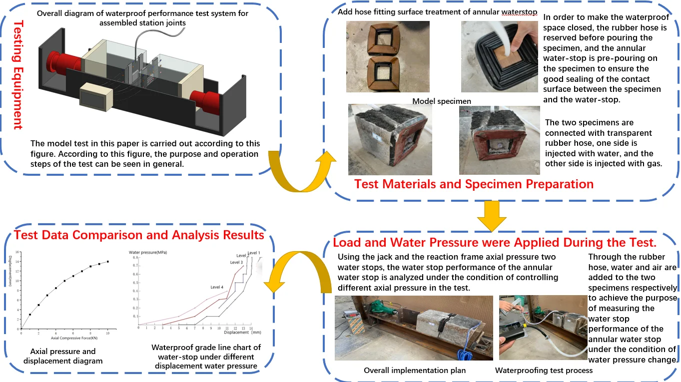
The overall scheme of the system with the joint size of 1:5 is shown in Fig. 1. The system is composed of field part and monitoring part.
The field part includes model specimen, water injection device and stabilizing device. The model specimen includes two assembled subway station joint test blocks, detachable rubber water stop belt, water injection device provides water pressure under different water pressure conditions for the assembled subway station joint test block, and the stabilizing device includes jack and jack reaction frame. It is used to detect the surface seepage of the joint of different test blocks in the assembled subway station and the water expansion of the detachable rubber water-stop.
The monitoring part includes concrete strain gauge, displacement sensor and humidity sensor, and collects sensor data through data collector, and then sends it to the data monitoring part through wired or wireless transmission to display the monitoring data. The monitoring equipment is considered to be installed near the side wall, and the site situation is considered.
Fig. 1The whole picture of the experimental system
3. Model test
In order to make the waterproof space closed, the rubber hose is reserved before pouring the specimen, and the annular water-stop is pre-pouring on the specimen to ensure the good sealing of the contact surface between the specimen and the water-stop.
Trim the annular water-stop, trim the water-stop according to the preset circumferential length of the annular water-stop, open a 90° groove to bend the water-stop, and finally connect it into an annular water-stop, as shown in Fig. 2. Pour the test block after the improvement scheme, clean the specimen die, brush the oil inside the mold, place the annular water-stop on one side of the mold, and seal the outer side of the water-stop with electric tape to prevent water immersion. A prism with a reserved hole is placed in the middle of the water-stop, and a transparent rubber hose is placed in the hole of the prism. The ratio of high-strength mortar to sand to water is 1:0.2. After stirring evenly, the test block is poured and cured for 24 h. The inner diameter of the transparent rubber hose is changed from 7 mm in the specimen to 8 mm, as shown in Fig. 3. The two specimens are connected to a transparent rubber hose for water injection on one side and gas injection on the other side.
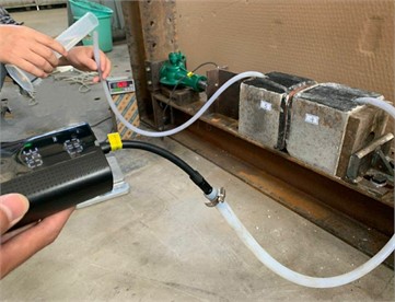
When testing the pressure test block, the pressure is applied in the same operation mode as the scheme one, that is, the annular water-stop of the two test blocks is placed in contact with the jack counterforce platform, the jack is connected to the force sensor, the force sensor is connected to the steel pad, the steel pad is connected to the specimen, and the other side of the specimen is connected to the steel pad to the counterforce frame, and the jack and the counterforce frame are axially pressed with two water stop belts, as shown in Fig. 4. Dyeing water is injected into one part of the thicker transparent rubber hose, and the vise seals the transparent rubber hose after being filled with water. The other part of the thinner transparent rubber hose is connected to the booster pump for gas injection. Each stage is 0.1 MPa until 0.7 MPa. The pressure is applied by the jack, and each stage is loaded with 1KN until 8KN. The loading process is shown in Fig. 5.
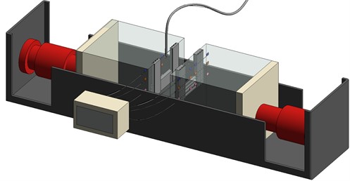
Fig. 2Annular water-stop with hose fitting surface treatment
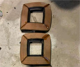
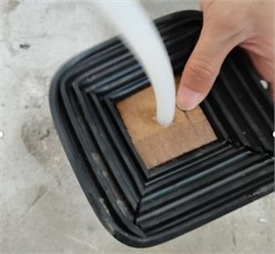
Fig. 3Model specimen
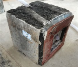
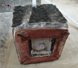
Fig. 4Overall implementation plan
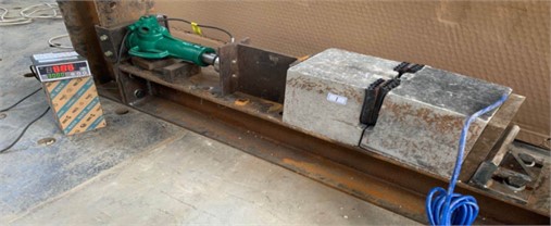
Fig. 5Waterproof test process
4. Test results
In Fig. 6, the displacement is the displacement of the jack, that is, the compression of the water-stop. The pressure is the axial pressure generated by the jack on the specimen. When the axial load is graded, the greater the pressure, the greater the compression of the water-stop. However, when the stage compression increases with the axial pressure, the growth rate decreases step by step. When the axial pressure continues to increase, the displacement curve will gradually converge, that is, the compression of the water-stop reaches the limit.
Table 1Waterproof test data
Axial pressure (KN) | Displacement (mm) | Water pressure (MPa) | Phenomenon |
0 | 23.5 (0) | 0 | four-stage |
1 | 20.5 (3) | 0 | three-stage |
2 | 18.5 (5) | 0 | single-stage |
0.1 | four-stage | ||
3 | 16.5 (7) | 0 | single-stage |
0.1 | three-stage | ||
0.2 | four-stage | ||
4 | 15 (8.5) | 0.1 | single-stage |
0.2 | two-stage | ||
0.3 | four-stage | ||
5 | 14.5 (10) | 0.1 | single-stage |
0.2 | two-stage | ||
0.3 | three-stage | ||
6 | 12.5 (11) | 0.2 | single-stage |
0.3 | three-stage | ||
0.4 | four-stage | ||
7 | 11.5 (12) | 0.3 | single-stage |
0.4 | two-stage | ||
0.5 | two-stage | ||
0.6 | three-stage | ||
8 | 10.5 (13) | 0.4 | single-stage |
0.5 | two-stage | ||
0.6 | two-stage | ||
0.7 | three-stage | ||
9 | 10 (13.5) | 0.5 | single-stage |
0.6 | single-stage | ||
0.7 | two-stage | ||
0.8 | two-stage | ||
10 | 9.5 (14) | 0.5 | single-stage |
0.6 | single-stage | ||
0.7 | single-stage | ||
0.8 | single-stage |
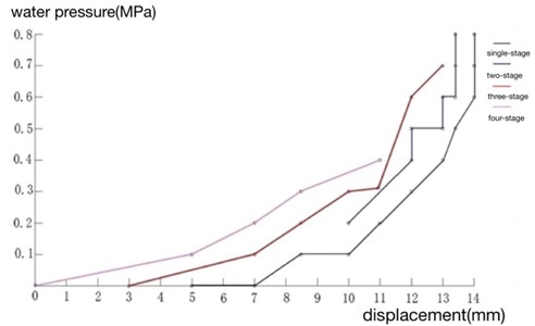
The minimum waterproof standard that the underground structure joint should meet is secondary waterproof. It can be seen from Fig. 7 that when the displacement is greater than 3 mm, that is, the compression amount of the water-stop exceeds 3 mm, the compression amount increases with the increase of the water pressure, which can meet the secondary waterproof standard of the underground engineering structure. When the compression amount of the water-stop exceeds 11 mm, the water pressure of the water-stop can reach 0.8 MPa, and the water pressure can basically meet the waterproof requirements.
Fig. 6Relationship between axial pressure and displacement
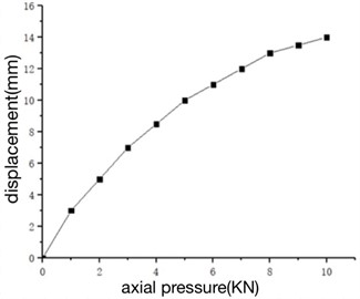
Fig. 7Line chart of waterproof grade of water stop under different displacement water pressure
5. Conclusions
1) Through the seam waterproof test, it is concluded that the resistance to water pressure of the expansion rubber water-stop increases rapidly when the compression amount is 40 %-48 %. When the water pressure reaches 0.75 MPa, the waterproof performance fails and the water-stop structure is destroyed when the compression amount of the water-stop is 80 %.
2) Through the waterproof test of the segment model test block, it is concluded that when the water pressure reaches 0.8MPa and the compression of the water stop is more than 11mm, it meets the secondary waterproof standard of the underground engineering structure. When the water pressure is 0.3 MPa-0.9 MPa, the seepage flow and the imbibition ratio sharply increase, and the trend of the curve is slowly increasing-suddenly increasing-stable. The imbibition ratio is positively correlated with the seepage volume, and the structural water absorption has no great influence on the waterproof performance of the segment gasket with different compression of the water stop.
3) According to the waterproof test results, the trend of the resistance to water pressure curve of the gasket in the segment test block prototype and the model is roughly the same. The resistance to water pressure of the seam material is larger than that of the previous two. The resistance to water pressure of the three decreases rapidly after the opening of the joint is 8mm. The waterproof performance of the composite elastic rubber gasket is better than that of the water expansion rubber water-stop.
References
-
C. L. Ye, Waterproof Work. Beijing: China Construction Industry Press, 1983.
-
Y. Liu et al., “Mechanical properties of waterproof adhesive layer on concrete box girder bridge,” Journal of Tongji University, Vol. 40, No. 1, pp. 57–61, 2012.
-
F. Mazzotta, C. Lantieri, V. Vignali, A. Simone, G. Dondi, and C. Sangiorgi, “Performance evaluation of recycled rubber waterproofing bituminous membranes for concrete bridge decks and other surfaces,” Construction and Building Materials, Vol. 136, pp. 524–532, Apr. 2017, https://doi.org/10.1016/j.conbuildmat.2017.01.058
-
X. Li, P. Huo, S. H. Zhou, D. W. Huang, and Q. Huang, “Test research on watertight mechanism and failure model of the double sealing gaskets in shield tunnel,” Journal of Railway Science and Engineering, Vol. 17, No. 1, pp. 159–166, 2020.
-
Z. X. Zhang, J. Sun, Y. F. Zhu, X. Huang, and W. H. Yuan., “Experimental study on waterproof performance of joint seal for deeply-buried storage and drainage tunnel,” Journal of Zhejiang University (Engineering), Vol. 52, No. 3, pp. 431–439, 2018.
-
Q. M. Xiao, G. Q. Xue, Y. Zhong, and W. H. Sun, “Experimental research on the waterproof of double gaskets in segment joint of shield tunnel,” Journal of Railway Engineering, Vol. 38, No. 2, pp. 85–91, 2021.
-
F. I. Shalabi, E. J. Cording, and S. L. Paul, “Concrete segment tunnel lining sealant performance under earthquake loading,” Tunnelling and Underground Space Technology, Vol. 31, pp. 51–60, Sep. 2012, https://doi.org/10.1016/j.tust.2012.04.006
-
S. Faisal, C. Edward, and P. Stanley, “Sealant behavior of gasketed-segmental concrete tunnel lining,” in 4th International Conference on Earthquake Geotechnical Engineering, pp. 1636–1648, 2007.
-
M. Wang, Q. Guo, P. Shan, M. Cai, F. Ren, and B. Dai, “Numerical research of fluid flow and solute transport in rough fractures under different normal stress,” Geofluids, Vol. 2020, pp. 1–17, Nov. 2020, https://doi.org/10.1155/2020/8845216
-
W. J. Zhang, G. L. Zhang, H. L. L., W. Y. Gao, W. S. Guo, and P. Gao, “Waterproof performance of sealing gaskets and impact of construction loads on segment joints in shield tunnel,” China Journal of Highway and Transport, Vol. 33, No. 12, pp. 130–141, 2020.
-
L. W. Dong, Y. S. Jiang, Z. Y. Yang, J. G. Cheng, C. Q. Liu, and J. J. Zhang, “Experimental study and water-resistant mechanism of gaskets in joints of tunnel segments,” Chinese Journal of Geotechnical Engineering, Vol. 39, No. 3, pp. 469–474, 2017.
-
L. Yan, W. Xu, B. Li, H. Ji, and J. Gu, “Evaluation of deformation and permeability behavior of amygdaloidal basalt under a triaxial cyclic loading creep test,” Geofluids, Vol. 2020, pp. 1–9, Nov. 2020, https://doi.org/10.1155/2020/6673530
-
S. Cui, J. Kong, H. Yu, C. Chen, and J. Wang, “Revising transient-pressure solution for vertical well intersected by a partially penetrating fracture with non-darcy flow effect,” Geofluids, Vol. 2020, pp. 1–17, Nov. 2020, https://doi.org/10.1155/2020/8884750
About this article

The authors have not disclosed any funding.
The datasets generated during and/or analyzed during the current study are available from the corresponding author on reasonable request.
The authors declare that they have no conflict of interest.
