Abstract
A two-dimensional system oscillation with massive bodies located in lattice nodes is investigated in this paper. The results of theoretical analysis and of the performed experiments are given. Certain modes of the oscillation of lattices of different dimensions are described.
1. Introduction
String lattice is a two-dimensional analogue of the classical system known as “thread with beads”. It can be used as a model of 2D-objects such as membranes, thin plates, panels, lattice structures of various sorting and sieving machines and devices, as well as crystals and nanostructures [1].
Linear models of string lattices are families of intersected strings forming rectangular cells. Each cell node contains a point perfectly rigid body. Such models were first studied in papers [2, 3]. String lattice dynamics with obstacles was considered in [4, 5]. Here we give the first experimental results on oscillations of such systems.
2. The equations of motion and their analysis
Let us consider a rectangular lattice [2, 3], composed of two orthogonal families of identical linear elastic strings fixed at the ends. String lengths are , respectively (Fig. 1). Each string is numbered by indices 0, 1, 2, …, and 0, 1, 2, …, . Point rigid bodies of equal masses m are placed into the lattice nodes.
Fig. 1a) Model of lattice 4×4. Oscillations modes: b) Θ11; c) Θ22; d) Θ12; e) Θ21


The rectangular lattice cells are equal; the string elements are inertialless. The strings are absolutely rigidly fixed in the nodes and tensions are so large that we can neglect possible changes of string lengths. A length of each cell “horizontal side” is ; and of “vertical one” is . “Horizontal” sides have tension , and “vertical” ones have tension . Let us describe lattice deformation by functions of lattice nodes displacements , where 0, 1, 2, …, ; 0, 1, 2, …, . Each of the functions defines a displacement of the node along an axis perpendicular to the plane of lattice static equilibrium. Horizontal strings are numbered by the first index , while vertical strings are numbered by the second index .
External forces are denoted as ; . For all nodes we have equations:
The boundary conditions are 0, 0, ; 0, . To write equations (1) in operator form we construct matrix dynamic compliance operators . We use four-index numbering for the dynamic compliance matrix components because each node is numbered by a pair of indices. Expression denotes the dynamic compliance operator [3-6], which connects the force, applied to the point , and node displacement . For the considered system we write the principle of reciprocity as . The system of equations (1) in this case can be written in operator form:
If the forces depend only on the time, Eq. (2) is linear and determines the solution of the problem. In general case we have a system of nonlinear equations for the unknown displacements of nodes. The case of periodic oscillations [3-5] is most well-studied. In particular, if any obstacle is installed near the lattices the system is vibro-impact.
To determine Eq. (2) we should describe the operators . The expressions for the dynamic compliance operators are completely determined by their natural frequencies and normalized coefficients of natural forms of a linear system [6]. Using the results from [2] we find:
Hence, [3]:
Thus, the parameters of oscillations in the linear case are fully defined and the necessary preliminary construction for the analysis in the case of non-linearities is carried out. Fig. 1(b-e) demonstrates the envelope surfaces of the four lower forms of free oscillations of 7×5 lattice, with nodal bodies not being shown.
Note that in case of isotropic lattices (; ; ; ) the number of different natural frequencies = and modes = decreases because of the system symmetry:
3. Experimental stand
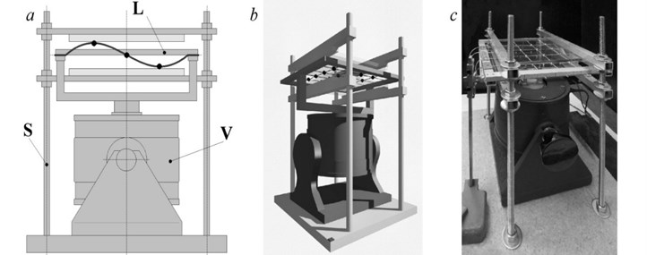
For experimental study of string lattices, we designed and constructed an experimental stand “Alligator Square” (Fig. 2), consisted of the working installation and of a control and registration system. Working installation includes a vibration exciter (V) and a system of interchangeable lattices (L) consisted of square aluminum frames (300×300 mm) with rubber bundles of 1mm in diameter. Bundles tensions and cells sizes are equal respectively. Lattice frame is fixed on the exciter platform. We manufactured lattices of 2×2, 3×3, 4×4. Lattices nodes are formed by 1.1 g washers placed at the points of bundles intersections. The washers were made of hardened steel. The installation enables the use of unilateral or bilateral obstacles made of glass sheets of 3mm thickness. The obstacles are installed on four supports (S) on a fixed base. The gaps values are set and regulated by micrometer screws.
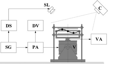
The control and recording system consists of a signal generator (SG), a power amplifier (PA), a digital stroboscope (DS), a digital voltmeter (DV), measurer for the vibration amplitude of the exciter platform (VA). Registration of standing waves profiles is carried out by camera (C), operating in both a photographing mode and the mode of accelerated filming. Strobe lamp (SL) illuminates the lattice. A phase shifter built-in into the stroboscope control unit can "stop" the lattice and take its picture at any time. At a small mismatch of 0.3-5.7 Hz we obtain a picture of slow evolution of the profile of the two-dimensional standing wave. The general scheme of the stand “Alligator Square” is shown in Fig. 3.
Fig. 2Working installation: a) scheme; b) draft; c) photo

Fig. 3Scheme of the “Alligator Square” experimental stand

The aim of the experiments is to give a quality experimental analysis of oscillation modes of string lattices with periodic excitation of oscillations.
4. The experiments results
In our case, the excitation is of kinematic nature: the frame oscillates sinusoidally. By changing the frequencies of the excitation we can study resonance phenomena.
We studied the lattices of 2×2, 3×3, 4×4. The relationships between the natural frequencies were estimated by Eq. (4). The natural frequencies of all the lattices lie within the segments . In this case, = 2, 3, 4. Natural frequencies distribution within these segments is uneven.
Fig. 4Lattice 2×2: mode Θ11; f11= 15.1 Hz; the amplitude of excitation μ = 5 mm

In the case of a 2×2 lattice we receive three different frequencies . Fig. 4 and Fig. 5 demonstrate oscillations with modes and and frequencies and where the final configurations of the systems over the half period are given.
In the case of a 3×3 lattice we receive six different frequencies . Fig. 6 shows a standing wave with oscillations of mode . Two senior modes of oscillations are shown in Fig. 7.
Fig. 5Lattice 2×2: mode Θ12 frequency f12= 28.4 Hz; amplitude of excitation μ = 5.2 mm

Fig. 6Lattice 3×3: mode Θ11; frequency f12= 15.1 Hz; amplitude of excitation μ = 5.2 mm

For a 4×4 lattice we receive a set of ten different natural frequencies , , , , , , , , , }, which belongs to the interval [, ]. Fig. 8 demonstrates the evolution of the mode .
When the number of nodes increases we face the problems with registration of the expected modes of oscillations, as we have distortions associated with the non-isotropy of the lattice and (or) non-linear factors. Fig. 9 shows the evolution of the standing wave at the implementation of oscillations on one of the highest forms. We can clearly see the transformation of the square lattice cells into the trapezoid ones. Such distortions can be seen also on Fig. 6 (a-b).
Fig. 7Lattice 3×3: profiles at frequencies a) f= 27.5 Hz, b) 36 Hz and c) amplitude of excitation μ = 5.4 mm

Fig. 8Lattice 4×4: standing wave profiles; frequency and amplitude of excitation f11= 15.2 Hz and μ = 2.4 mm

Fig. 9Lattice 4×4: profiles of the standing wave at frequency f= 29 Hz, amplitude of excitation μ = 3.5 mm

5. Remarks on vibro-impact processes study
We performed experiments to study vibro-impact regimes of 2×2 and 3×3 lattices. The researches were carried out at frequencies of excitation higher than for lattices of both types. The regimes of the synchronous claps [4, 5] were visually observed. We intend to accomplish a comprehensive interpretation in our subsequent works.
6. Conclusions
Experiments with two-dimensional lattice structures show that linear models in lattice constructions with a high number of nodes work well for analysis of the lower modes of oscillations. Analysis of the higher modes of oscillations demands taking into account non-linear factors. Therefore, it is required the creation of more general theories and the development of more advanced experimental stands.
References
-
Astashev V. K., Krupenin V. L., Perevezentsev V. N., Kolik L. V., Andrianov N. A. Properties of surface layers nanostructured by autoresonant ultrasonic turning. Journal of Machinery Manufacture and Reliability, Vol. 40, Issue 5, 2011, p. 68-72.
-
Nagaev R. F., Khodzhaev K. Sh. Kolebaniya Mekhanicheskikh System s Periodicheskoi Strukturoi (Vibration of Mechanical Systems with Periodic Structure). FAN, Tashkent, 1973, p. 220, (in Russian).
-
Krupenin V. L. On the calculation of vibratory processes in lattice two-dimensional constructions. Problemy Mashinostroeniya i Nadezhnosti Mashin, Vol. 2, 2006, p. 20-26, (in Russian).
-
Krupenin V. L. Vibroimpact processes in two-dimensional lattice constructions. Problemy Mashinostroeniya i Nadezhnosti Mashin, Vol. 3, 2006, p. 16-22, (in Russian).
-
Krupenin V. L. Analysis of singularized motion equations of latticed vibroimpact 2D systems in renouncing Newton’s hypothesis. Journal of Machinery Manufacture and Reliability, Vol. 45, Issue 2, 2016, p. 104-112.
-
Babitsky V. I., Krupenin V. L. Vibration of Strongly Nonlinear Discontinuous Systems. Springer-Verlag, Berlin, Heidelberg, New York, 2001, p. 404.
About this article
The study was performed account for a grant the Russian Science Foundation (Project No. 15-19-30026).
