Abstract
Stirred tanks are widely used in many industries for manufacture of solutions, emulsions and suspensions. Traditional rotational mixers do not allow to achieve the required heat and mass transfer, so many papers are devoted to the creation and research of devices that provide vibrational effect on the stirred product. Rotationally reciprocating stirred tanks are more manufactured in comparison with reciprocating stirrers, since they use standard bearing units and seals. As an actuator of vibromixer it is proposed to use a planetary mechanism with elliptical gearwheels, which converts the rotational motion of the motor into reciprocating rotational motion of impeller. Dynamic model of the stirred tank is constructed by reduction of the forces, masses and moments to primary link (an actuator input shaft). Analysis of the dynamic model was carried out by energy-mass method; as a result, we found the law of motion of the input shaft and the moment of inertia of the flywheel.
1. Introduction
Stirring is one of the most widespread processes in machine building, petrochemical, construction, chemical, food industry [1, 2]. Stirred tanks are widely used for manufacture of solutions, emulsions and suspensions. Currently, stirrers with rotational motion of impellers are the most common and investigated, but they do not achieve a high intensity of heat and mass transfer in the reactor.
In [3-4] stirred vessels are investigated, providing vibration impact on the product due to the reciprocating motion of the impeller. Such mixing method promotes intensification of technological processes causing reduction the time of their occurrence in the 1.5-2 times [4]. However, disadvantages of such devices are significant vertical vibrations which are transmitted to the environment and complicate the job of the operator, as well as the linear motion of the rod which is difficult to seal, so such stirrers are unreliable and cannot be used in reactors operating under pressure.
Stirrers with rotationally reciprocating motion of impellers have such vibration effect on the product, while they lack vertical vibration and have the standard seals. Thus, the creation and study of rotationally reciprocating stirred tanks is an actual problem.
2. Development of mixers with rotationally reciprocating motion of impellers
The simplest solution of the problem is a stirred tank in which the rotationally reciprocating motion of impeller is provided by reversing motion of the stepping motor. Such design was developed in [5, 6], and it allows to conduct various experiments in the small volume reactors because of the wide range of the rotation angle. However, the use of such device is impractical on an industrial scale, since the stepping motor has a low efficiency and cannot be used at high oscillation frequency of impeller.
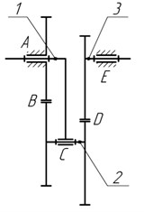
The required motion of impellers can be obtained using a mechanical converter of rotational motion into reciprocating rotational one as an actuator of the stirred tank. In [7] the structural synthesis of the actuator was conducted, so the following actuators were obtained: four-bar linkage (Fig. 1) and planetary mechanism with elliptical gearwheels [8] (Fig. 2).
Fig. 1Structural scheme of a four-bar linkage: 1 – crank, 2 – connecting rod, 3 – rocker; A, B, C, D – 1-DOF kinematic pairs
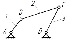
Fig. 2Structural scheme of a planetary mechanism: 1, 2, 3 – links; A, C, E – 1-DOF kinematic pairs, B, D – 2-DOF kinematic pairs
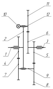
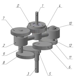
Synthesized mechanisms are formed from highly reliable and well-proven devices. The planetary gear is more compact compared to the lever mechanism; besides its input and output shafts are located on one axis, making it more promising for practical implementation. Since the unbalanced inertia forces will occur in the device (Fig. 2), we investigate double-satellite planetary mechanism as an actuator of stirred tank, where there is counterweight on an additional satellite (Fig. 3).
Fig. 3Balanced planetary gear: a) kinematic scheme, b) design
a)
b)
Planetary gear (Fig. 3) consists of a rack 0, the input shaft 1, the carrier 2, the output shaft 3, the sun gear 4, elliptic gears 5 and 6 (at an angle of 180°) on output shaft, the first satellite, consisting of a cylindrical gear 7, elliptical gear 8 and shaft 9, the second satellite, consisting of the counterweight 10, elliptical gear 11 and shaft 12. Reciprocating rotational motion is provided by the variable transmission ratio of elliptical gears. With correct selection of links and counterweight masses, the investigated mechanism is balanced, and therefore, it will not have adverse vibrations.
One of the most responsible stages in the new machines development is to study their dynamics. To study the dynamics of rotationally reciprocating mixing tank let’s construct its dynamic model and carry out its analysis.
3. Dynamic model of vibromixing stirred tank
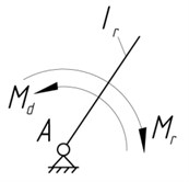
Planetary actuator has one degree of freedom and its links are rigidly interconnected, so to solve the problem we will take the input shaft 1 as a reduction link (Fig. 3). Then single-mass dynamic model of stirred tank takes the form (Fig. 4).
Fig. 4Single-mass dynamic model
To find the law of reduction link motion, let’s define the following parameters of the dynamic model: reduced moment of inertia and the reduced moment of resistance forces . The required drive moment is calculated during the analysis of the dynamic model.
According to [9-11], the reduced moment of inertia is determined by:
where is the number of movable links, the masses and inertia moments of which are known; is the mass of the -th link; is moment of inertia of the -th link about an axis passing through the center of mass; is a velocity analogue of the -th link center of mass; is an angular velocity analogue of the -th link.
For designed planetary mechanism Eq. (1) takes the following form:
where is the motor moment of inertia, is impeller moment of inertia. The moments of inertia and velocity analogues of the actuator links identified in accordance with Fig. 3.
Given that , , we transform Eq. (2) and obtain:
Differentiating Eq. (3) according to the generalized coordinate, we get:
As seen from Eq. (3), (4), to find the reduced moment of inertia and its derivative it is necessary to find kinematic characteristics of planetary actuator. In [11] kinematic parameters for another planetary gear with two pairs of elliptical wheels were found, but they can be used for the mechanism, shown in Fig. 3, if it is assumed that the circle is an ellipse with an eccentricity .
According to [9], reduced resistance moment is generally defined as follows:
where is a total number of mobile links; is number of forces , acting on the -th link; is velocity analogue of force application point; is the number of moments , acting on the -th link.
Taking into account that only the impeller resistance moment acts in the stirred tank, then Eq. (5) to determine the reduced resistance moment takes the form:
Most of the processes are effective in high-frequency oscillations of the impeller, which are characterized by turbulent fluid motion. For the turbulent regime, according to [12], moment of resistance is determined as follows:
where is reduced coefficient of quadratic resistance, is the angular velocity of impeller, is an impeller length, is the blade width.
Given that and , we substitute Eq. (7) to Eq. (6) and obtain:
Thus, Eq. (3), (4), (8) describe the dynamic model of vibromixing reactor with reciprocating rotational motion of the impeller.
4. Analysis of the dynamic model
Let’s investigate stirring vessel with the following parameters (link numbers correspond to Fig. 3): = 100 g·cm2 (motor); = 9.8 g·cm2; = 1233 g·cm2; = 30.4 g·cm2; = = 627 g·cm2; = 400 g·cm2, = 0.1 kg; = =564 g·cm2, = = 0.09 kg; = 19.2 g·cm2, = 0.04 kg; = 350 g·cm2, = 0.09 kg; = 25 g·cm2, = 0.05 kg; = 15 g·cm2, = 0.045 m, = 0.12 m (impeller); = 6·10-7; allowable coefficient of rotation irregularity = 0.05. The eccentricity of elliptical wheels = 0.5, semi-major axes of elliptical wheels = 25mm. Input shaft of actuator driven by a motor, which rotating speed = 52 rad/s ( = 500 rpm).
Dynamic model analysis is provided using the energy-mass method [9], which is widely used in the dynamic analysis of machines. According to the chosen method we will find the increment of the kinetic energy :
where is work of driving forces (), is work of resistant forces.
Angular velocity of reduction link is determined as [9]:
where , .
Using Eq. (9) and Eq. (10), we construct a graph (Fig. 5).
Fig. 5Graph of function ω1(t)
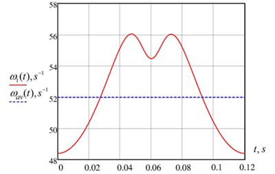
The graph shows that the reduction link angular velocity is not constant and varies around the average value. Velocity oscillations are determined by the intracyclic changes in gear ratio of mechanism with elliptical gearwheels and force changes on impeller. Since the angular velocity of reduction link is variable, then we define coefficient of rotation irregularity [9]:
It is seen from Fig. 5 that = 56.05 rad/s, = 48.4 rad/s, =52 rad/s. Then coefficient of irregularity is = 0.15. It can be seen that the found coefficient does not satisfy the previously allowed coefficient = 0.05. Therefore, it is necessary to install the flywheel in the investigated vibromixing stirrer.
The angular velocity of reduction link with flywheel is determined as [10]:
where the required flywheel moment of inertia is . Angular velocity of reduction link is shown in Fig. 6.
Fig. 6Graphs of functions ω1(t) with and without flywheel
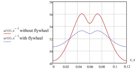
As can be seen from the graphs, that the installation of a flywheel reduced rotation irregularity of reduction link. Coefficient of rotation irregularity decreased to allowable value = 0.05.
5. Conclusions
It is proposed to use a balanced planetary mechanism with elliptical gears as an actuator of vibromixing reactor with rotationally reciprocating impeller. Single-mass dynamic model of the machine was built to study the dynamic processes and its analysis was conducted by energy-mass method. As a result of the research the actuator input shaft law of motion was found, as well as the flywheel moment of inertia was determined. The flywheel is required to reduce coefficient of rotation irregularity to allowable value. Let us note that the angular velocity irregularity in the investigated mechanism promotes efficiency of heat and mass transfer processes.
References
-
Cullen P. Food Mixing: Principles and Applications. Wiley-Blackwell, 2009.
-
Hemrajani R., Tatterson G. Mechanically Stirred Vessels. Handbook of Industrial Mixing: Science and Practice, 2004, p. 345-390.
-
Ibanescu C., Lungu M., Lungu G., Sachelarie A. Study on vibromixing for polymer solutions. Iranian Polymer Journal, Vol. 7, Issue 2, 1998, p. 129-135.
-
Smelyagin A., Yukhnevich I. Structural and parametric synthesis of vibromixing devices actuator. Food technology, Vol. 15, Issues 2-3, 2013, p. 93-96, (in Russian).
-
Senda S., Yamagami N., Komoda Y., Hirata Y., Suzuki H., Hidema R. Power characteristics of a rotationally reciprocating impeller. Journal of Chemical Engineering of Japan, Vol. 48, Issue 11, 2015, p. 885-890.
-
Senda S., Komoda Y., Hirata Y., Takeda H., Suzuki H., Hidema R. Characteristics of flow filed induced by a rotationally reciprocating plate impeller. Journal of Chemical Engineering of Japan, Vol. 49, Issue 4, 2016, p. 341-349.
-
Prikhodko A., Smelyagin A. Structural synthesis of stirred tanks with swinging motion of impellers. Vestnik Donskogo Gosudarstvennogo Tekhnicheskogo Universiteta, Vol. 15, Issue 4, 2015, p. 69-75, (in Russian).
-
Prikhodko A., Smelyagin A. Kinematic analysis of mechanism for converting rotational motion into reciprocating rotational motion. Procedia Engineering, Vol. 129, 2015, p. 87-92.
-
Smelyagin A. Mechanism and Machine Theory. Infra-M, Moscow, 2014, (in Russian).
-
Prikhodko A., Smelyagin A. Dynamic analysis of rotationally reciprocating stirred tank with multiple impellers. International Conference on Mechanical Engineering, Automation and Control Systems (MEACS), 2015, p. 1-5.
-
Prikhodko A., Smelyagin A. Dynamics of rotationally reciprocating stirred tank with planetary actuator. International Conference on Dynamics of Systems, Mechanisms and Machines (Dynamics), 2016, p. 1-6, (in Press).
About this article

