Abstract
Two-sided laser shock processing (TSLSP) is often employed to improve the surface quality of thin section components, which can reduce excessive plastic deformation induced by one-sided laser shock processing. Residual stresses (RS) field induced in a thin Ti-6Al-4V alloy plate by TSLSP was investigated through numerical simulation. The multiple TSLSP impacts and the increasing laser shock pressure were found to have significant effects on the RS field. Microhardness distribution on the section of specimen, calculated from RS by Carlsson-Larsson model, is analyzed
1. Introduction
Residual stresses (RS) are often left in the material as a result of plastic deformation after the metal components are processed. Compressive residual stresses (CRS) can improve the fatigue life of the components in practice, while tensile residual stresses (TRS) have an adverse effect on the fatigue resistance. In order to prolong the fatigue life of the components, the CRS are always introduced into its surface layer through various surface treatment techniques, such as shot peening, ultrasonic peening, cold extruding and cold rolling. Laser shock processing (LSP) is an emerging surface modification technology, which employs laser to irradiate metal surface and to introduce the CRS into surface layer. Compared with other peening technologies, LSP can penetrate the CRS deeper into the material at the cost of less defects on treated material surface, so the processed component has a robust resistance to crack initiation and crack growth [1], and its fatigue life is improved prominently [2].
These investigations are very useful for gaining insight into the RS field induced by LSP, but most of abovementioned researches have only focused on one sided LSP on thick components. If one sided LSP is implemented on the surface of thin section metal components, it leads to detrimental deformation, even fracture, which results from the strong unbalanced impacting force generated by laser. Therefore, two sided LSP (TSLSP) has to be employed to process the thin section metal components, for example the edges of fan blade in aero-engine can be repeatedly impacted by laser to improve its resistance to foreign object damage. The TSLSP is a technique, which uses two same laser pulses to fire dual sided surfaces of component. The laser-generated pressure from one surface of target counteracts that from the opposite surface, so the excessive harmful deformation of the target can be reduced. Up to now, few attentions have been paid to the RS created by TSLSP. In [3] initially is established FEM model with ABAQUS to simulate the RS resulted from TSLSP. In [4] is made advancements in simulating the dynamic stress and RS induced by TSLSP under different processing conditions, and claimed that the TRS occurred in the mid-plane region of metal sheet after TSLSP treatment [5-7]. Hence, further research work is needed to investigate the CRS distribution induced by TSLSP impact. Moreover, there have been no published references to disclose systematically the fundamental principle of RS field in the thin section components subjected to TSLSP, and some distribution characteristics of RS field are still unknown. Therefore, the RS field induced by TSLSP is a topic that can be researched to get more in- sights into TSLSP to eventually improve this technique.
The aim of present work was to gain better understanding the RS field distribution induced by TSLSP. The micro-hardness distribution on the section of titanium alloy specimens is calculated by fined RS.
2. Principle of TSLSP
The schematic of TSLSP is shown in Fig. 1. The target surface to be shocked by laser is first coated with an ablative layer (aluminum foil or black paint), which is served as the protect layer to avoid material to be ablated by laser. And then, each ablative layer surface is covered with a transparent layer (glasses or water curtain), which is used as the confined overlay to raise the peak pressure of shock wave and to prolong its action time. Finally, a high-power and short-duration laser pulse is emitted from the laser, and split by a beam splitter into two same pulses. Each branch pulse independently travels through the transparent overlay, and they simultaneously irradiate onto the surfaces of ablative layer. The ablative material is vaporized almost simultaneously, and the high pressure plasma is generated in an ultra-short time. The extremely rapid expansion of the plasma on each side of target exerts the pressure on its surface, and the target material is com pressed. As a result, the stress wave is induced and propagates in material. When the peak pressure of stress wave goes beyond the dynamic yield strength of the material, the permanent plastic deformation yields at the local impacted zone, and its surrounding material is elastically compressed simultaneously. After the pressure unloading, the sur rounding elastically condensed material tries to get back to its original state, but is held back by the plastic deformation. So, the plastic strain layer of the target is subjected to CRS, and the region next to this layer is subjected to TRS to maintain equilibrium in the target without external force. Due to the symmetric pressure loading, the symmetric RS fields are always obtained in symmetric geometry structures.
Fig. 1The schematic of TSLSP: 1 – target, 2 – laser beam, 3 – trapped high pressure plasma, 4 – transparent overlay, 5 – ablative layer, 6 – shock wave, 7 – laser beam axis, 8 – mid-plane
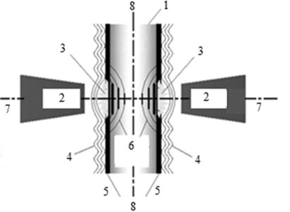
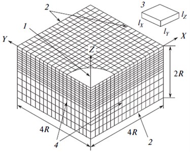
Fig. 2The scheme of the 3D finite element model for TSLSP: 1 – TSLSP zone, 2 – nonreflective surface, 3 – finite element, 4 – planes of symmetry
3. Numerical simulation
Material response to LSP with FEM has been reported extensively [5-7]. The commercial codes ABAQUS/Explicit and ABAQUS/Standard have been widely used to simulate RS created by LSP [3-4]. They were also employed to simulate material response to TSLSP in the present work. It included the dynamic analysis step and the following static analysis step. ABAQUS/ Explicit was first utilized to conduct dynamic calculation. In this step, the dynamic analysis was implemented to capture the material rapid response to laser shock, for example stress wave propagation and dynamic stresses at different times. After the dynamic calculation completion, the obtained transient results were input into ABAQUS/Standard to perform static calculation. The static analysis was applied to release the elastic strain energy stored in material, and to obtain the final RS distribution in the static equilibrium state. In simulation of multiple TSLSP impacts with identical model parameters at the same location, the RS remained in the target after the last shock was served as the initial stress for the next shock. For example, the RS incurred from the first impact was used as the initial stress for the second impact. After several rounds of simulation, the corresponding RS induced by several successive impacts could be obtained finally.
4. Finite element model
Finite element simulation was carried out using the ANSYS software (license no. 660578). To avoid many difficulties in the fast dynamic problem, the calculations are carried out in a symmetric finite element model with the dimensions of 4×4×2, where is the radius of the laser spot (in this case, 3 mm) (Fig. 2). The finite element size is 10, 20, where is the finite element size on axes , ; and is the size on the axis . The time step is 0,22 ns.
5. Loading applied
In simulation, laser local spot was 3 mm in diameter. Laser pulse with a full width at half maximum (FHWM) was 8 ns. Laser spot and FHWM kept constant. Laser output energy of per pulse varied, which was directly related to laser power density and shock wave pressure. According to the confined model developed by Fabbro et al. [1], the plasma pressure and the thickness of interface have the following relationships:
where is the laser power density and:
where is the fraction of the internal energy devoted to the thermal energy (α varies in the range from 0,1 to 0,2. In case of using water as the medium, 0,11; physically, this means that only 11 % of the starting energy of laser radiation is used in increases in plasma pressure); is the reduced shock impedance between the confining layer and the ablative layer material , which can be defined by:
where and stand for the ablative layer material impedance and confining medium impedance the respectively (, e.g., for aluminum, it is equal to 2,5×10⁷ kg/(m2s), is the impedance of the medium, e.g., for water, it is equal to 1,65×10⁷ kg/(m2s)). Assuming that the laser power density keeps constant, the peak plasma pressure in the confined mode can be estimated by the following formula:
In addition, with reference to the above confined model [4], the action time of high pressure plasma lasts two to three times longer than the duration of laser pulse. Therefore, the loaded pressures could be depicted as in the following Fig. 3, which were applied uniformly to the entire laser local spot on each side surface of target.
6. Material constitutive relation
Target material was assumed to be an elastic-plastic homogeneous isotropic material, and its initial stress was assumed to be 0 MPa. In LSP, material strain rate is very high and reaches up to 106 s-1, so the constitutive relation obtained from quasi static conditions is no longer valid. The Johnson-Cook (J-C) model takes into account the strain hardening, the strain rate effects and thermal effects on the flow stress in material, which has been widely applied to simulate the material response to high strain rate and large strain. It is expressed as follows [8]:
where and represents the equivalent stress and plastic strain, – dimensionless equivalent strain rate, is the yield stress at the reference strain rate ( 1,0 s-1). and exponent represent the strain hardening effect; stands for the strain rate hardening effect. is homologous temperature, which is given by:
where and stand for the melting point of material and room temperature respectively. In the case of LSP, the ablative layer was sacrificed to protect the target from laser irradiation, so the target could be shielded from laser thermal effects. Therefore, the temperature effect in the J-C model could be neglected. The parameters of Ti-6Al-4V used herein were listed in Table 1.
Fig. 3Temporal pressure profiles for differ laser power densities: 1 – 2,1 GW/cm2, 2 – 5,4 GW/cm2, 3 – 12,2 GW/cm2
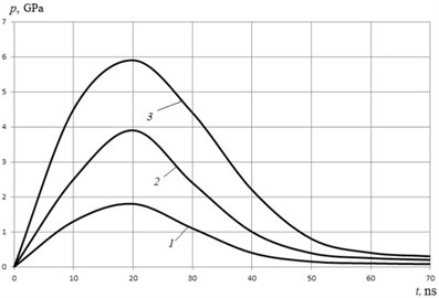
Table 1Physical and mechanical properties of Ti-6Al-4V [4]
Properties | Value | Dimension |
Density, | 4500 | kg/m3 |
Poisson’s ratio, | 0,342 | – |
Elastic modulus, | 110 | GPа |
Hugoniot elastic limit | 2,8 | GPа |
1098 | MPа | |
1092 | MPа | |
0,93 | – | |
0,014 | – |
7. Results and discussion. Residual stress and Micro-hardness distribution
In laser peening, severe plastic deformation could be induced by laser peening in the material surface, often resulting in compressive residual stresses in surface and sub-surface of metal material. The residual stress distribution curves on the cross-section with different laser peening parameters are depicted in Fig. 4. Curve 1 represents origin material (before TSLSP).
Curve 2 represents laser energy of 5 J and impacts of 1 times, 3 – represents laser energy of 7 J and impacts of 3 times. As shown in Fig. 4, compressive residual stress in 4 mm thick specimens was introduced by laser peening, and the thickness of the compressive layer varies between 20 µm and 1.6 µm according to the process conditions, with the most severe laser peening conditions, the maximum compressive stress value reaches − 524 MPa at a depth of about 150 µm, while the surface stress reaches − 492 MPa. The compressive residual stresses are also found to increase with the increasing of laser pulse energy and impact times.
For hardness, it is well known that the residual or applied macro-stresses may influence the hardness measurements performed with a sharp or a blunt indenter. Many studies establish a quantitative link between the two quantities. In the present study, the model proposed by Carlsson and Larsson [9] is used to separate the contribution of residual stresses and the contribution of work-hardening on hardness measurements. This model leads to hardness variations expressed by:
where is the stress free hardness, is the residual stress value and is the initial yield stress of the material. Their model was established in the case of equibiaxial plane stress state, assumed to be homogeneous over the whole volume affected by the indenter.
Hardness is a basic mechanical property of metal material, which can be defined as the resistance to indentation. Higher hardness value can bring in a better property of resistance for the wear and foreign object damage to some extent. Fig. 5 shows the micro-hardness distribution on the section of titanium alloy specimens with different impact times, calculated by Eq. (7). Curve 1 – represents origin material (no TSLSP), 2 – represents impact 5 times, 3 – represents impact 10 times. The original hardness is about 320 HV0.2. After laser peening, the laser peening leads to a moderate increase in hardness. Using the most severe laser peening parameters, the maximum micro-hardness value reaches 415 HV0.2 at the material surface, similar to the distribution law of residual stress.
Fig. 4Residual stress distribution on cross-section
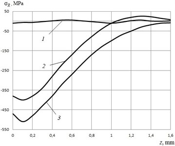
Fig. 5Micro-hardness distribution on cross-section with laser energy of 7 J
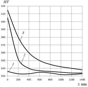
The surface micro-hardness increases about 26.2 %, 26.7 %, 28 % and 29 % respectively for 1 impact, 2 impacts, 5 impacts and 10 impacts. The surface micro-hardness increases with laser peening impact times, but the further increased amplitude is limit, only 2-3 %. However, the hardened layer depth increases significantly with laser peening impact times. The affected depth of hardness is about 550 µm for one impact times, 800 µm for 2 impact times, 950 µm for 5 impact times and 1400 µm for 10 impact times, it is also well consistent with the distribution rule of residual stress. In depth, the micro-hardness decreases with depth, but there is a severe hardened layer, which is about 400 µm. We also can see that the hardness decreases gradually below the severe hardened layer.
8. Conclusions
A 3D finite element model was developed to predict the RS induced in Ti-6Al-4V alloy plate subjected to TSLSP treatment.
The laser energy and impact times have an influence on residual stress value. With the most severe laser peening conditions, the maximum compressive stress value reaches − 524 MPa at a depth of about 150 µm, while the surface stress reaches − 492 MPa.
Microhardness distribution on the section of specimen is calculated from RS by Carlsson-Larsson model. Using the most severe laser peening parameters, the maximum micro-hardness value reaches 415 HV0.2 at the material surface, similar to the distribution law of residual stress. The hardened layer depth increases significantly with laser peening impact times. The affected depth of hardness is about 550 µm for 1 impact times, 800 µm for 2 impact times, 950 µm for 5 impact times and 1400 µm for 10 impact times.
References
-
Peyre P., Scherpereel X., Berthe L., Fabbro R. Current trends in laser shock processing. Surface Engineering, Vol. 14, 1998, p. 377-380.
-
Zhang Y. K., Lu J. Z., Ren X. D., Yao H. B., Yao H. X. Effect of laser shock processing on the mechanical properties and fatigue lives of the turbojet engine blades manufactured by LY2 Al alloy. Materials and Design, Vol. 30, Issue 5, 2009, p. 1697-1703.
-
Ocana J. L., Morales M., Porro J. A., Dнaz M., Ruiz de Lara L., Correa C., et al. Induction of Thermo-Mechanical Residual Stresses in Metallic Materials by Laser Shock Processing. Encyclopedia of Thermal Stresses, 2014, p. 2427-2444.
-
Hu Yongxiang, Yao Zhenqiang Numerical simulation and experimentation of overlapping laser shock processing with symmetry cell. International Journal of Machine Tools and Manufacture, Vol. 48, 2008, p. 152-162.
-
Sakhvadze G. Zh., Gavrilina L. V. Single and multiple laser shock processing of materials. Journal of Machinery Manufacture and Reliability, Vol. 6, 2015, p. 75-80.
-
Sakhvadze G. Zh., Gavrilina L. V., Kikvidze O. G. Influence of laser spot overlap effect on residual stresses during laser-shock-wave processing of materials. Journal of Machinery Manufacture and Reliability, Vol. 3, 2016, p. 258-265.
-
Sakhvadze G. J. Laser shock processing of materials to produce nanostructures. Special Issue of Scientific Journal of IFToMM “Problems of Mechanics”. Vol. 2, Issue 55, 2014, p. 68-73.
-
Johnson G. R., Cook W. H. A constitutive model and data for metals subjected to large strains, high strain rates and high temperatures. Proceedings of the 7th International Symposium on Ballistics, The Hague, 1983, p. 541-547.
-
Carlsson S., Larsson P. L. On the determination of residual stress and strain fields by sharp indentation testing. Part 1: theoretical and numerical analysis. Acta Materialia, Vol. 49, 2001, p. 2179-2191.
About this article

The work is financially supported by the Ministry of Education and Sciences of the Russian Federation within the federal target Program “Studies and Developments of Promising Trends in Russia’s Science and Technology Sector for 2014-2020”. Subsidy Agreement No. 14.607.21.0040 of July 22, 2014, Project RFMEFI60714X0040.
