Abstract
Virtual modeling and simulation are increasingly used to help develop restraint systems, and airbag simulation is the necessary steps during airbag research and design progress. In this work, the squeezed airbag has been simulated by a uniform pressure method in which the pressure of the airbag is considered as constant. The main aim of this study is evaluate the performance of deploying of passenger side airbag using finite element methods (FEM) to handle different collision scenarios.
1. Introduction
Traffic accidents are one of the leading causes of mortality in modern society. Therefore, while it is desirable to retain the convenience and social functions afforded by automobiles, it is essential to reduce the number of deaths on the road. Hence, manufacturers now incorporate a wide range of safety devices and features into their vehicles, including airbags, energy-absorbing steering columns, side door beams, etc. [1, 2]. The seat belt is designed to restrain the occupant in the vehicle and prevent the occupant from having harsh contacts with interior surfaces of the vehicles. The airbag acts to cushion any impact with vehicle structure and has positive internal pressure, which can exert distributed restraining forces over the head and face [3]. Evaluating the effectiveness of these protective devices involves investigating the dynamic response of these devices in a traffic accident situation [4]. The information provided by such investigations enables vehicle manufacturers to modify their designs appropriately in order to enhance the occupant’s safety. Airbag has been widely used in the automotive industry to protect occupants in the events of side impact and rollover. There are various types of airbags; frontal, side-impact and curtain airbags. In the vehicle, airbag is folded and installed on the cantrail behind roof headliner. When the collision occurs, the airbag is deployed, pushes the headliner out of the way and positions itself between occupant and side windows of the vehicle to protect the occupant (see Fig. 1).
In the process of the deployment, different phases can be observed. Firstly, the generator starts to inject gas into the bag. At this stage the airbag is contained by its housing and cover, which prevent it from deploying freely. At a certain moment the pressure grows enough so as to burst the seam that maintains the cover closed. Then, the bag starts to protrude, being able at this point to increase its volume. At the beginning of this stage the pressure is still high, and the bag is propelled violently. When the pressure inside the airbag has become closer to the atmospheric pressure, the bag keeps on developing until there is no more folded fabric in the case. At this point we can consider that the deployment has finished and that the airbag is ready to receive the occupant.
Fig. 1a) Frontal and side airbags, b) oblique view of facet occupant model in sitting posture following airbag deployment (Lim et al., 2014)
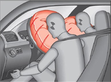
a)
b)
Many studies, experimental and numerical, have examined different parameters to identify vehicle crash conditions. Bankdak and al. (2002) developed an experimental airbag test system to study airbag-occupant interactions during close proximity deployment. The results provided insight for simulating the effect of inflation energy and mass flow on target response [5]. Bedard et al. (2002) found that while left-side (driver-side) impacts accounted for only 13.5 % of all crashes, the fatality rate among these crashes was 68.3 % in comparison to front impact (48.3 %), right-side impact (31.3 %), and rear impact (38.4 %). These studies underscore the importance of occupant safety during side impact collisions [6]. In the last years, current market request to reduce the time and cost airbag development. In order to achieve this result, virtual simulations play an important role since they allow to minimize the number of experimental tests [7, 8]. Several simulation models of airbag were established [9]. It’s feasible to optimize the parameters of airbag deployment using simulation technology. Experimental and numerical studies have quantified injury risks to close-proximity occupants from deploying side airbags. These studies have focused on the prevention of the most adverse effects of airbag deployment. The duration from the initial impact of the crash to the full inflation of an airbag is about 40 milliseconds and during this time, the airbag goes from being in a folded state to a fully inflated state, with a high internal pressure. After achieving this state, the airbag begins to deflate, thus providing a nice cushion for the body impacting it. Ideally the person in the crash should come into contact with the airbag at this time. In the field of vehicle development numerical simulations are essential due to the complexity and high costs of full scale crash tests. The main aim of this study is evaluate the performance of deploying and squeezing of passenger side airbag using finite element methods.
2. Finite element model of airbag simulation
2.1. Theoretical background
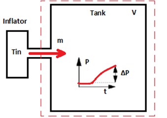
The amount of mass injected into the airbag needs to be defined with respect to time. The data can be obtained by airbag manufacturer or a tank experiment. A diagram of a classic tank experiment can be seen in Fig. 2.
The gas exerts a pressure load on the airbag causing it to expand. This expansion puts the airbag under tensile stress lowering the expansion rate. In this study, heat conduction and heat transfer is not taken into account. In the deployment of an airbag an inflator supplies high velocity gas into an airbag causing it to expand rapidly.
The gas inside the airbag is assumed to be ideal, to be of constant entropy and to satisfy the equation of state:
Fig. 2Functional principle of the airbag deployment
The gas flow is described by the conservation laws for mass, momentum and energy that read:
Applying Bernoulli’s equation in the case of an ideal gas with constant entropy gives:
Here the subscript denotes quantities at the throat of the tube. Furthermore, , and denote the quantities inside that part of the tube that is supplying mass. This one gives:
2.2. Materials and boundary conditions
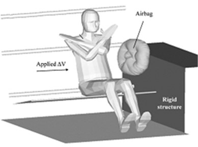
The impactor is a rectangular plate with size of 650 mm in length, 350 mm in width, and 10 mm in thickness. Table 1 shows the physical and mechanical properties of the impactor. In the experiment, the plate was released from a certain height varied from 200 mm to 500 mm. To study the effect of an impact, the initial velocity of the rigid wall was kept at 27.77 m/s. For each impactor height, five specimens were tested, and acceleration/deceleration of the impactor was recorded in each test (see Fig. 3(a)). The airbag system mainly consists of three parts: the airbag itself, the inflator unit and the crash sensor or diagnostic unit. Thus, to study the behavior of the airbag using FE simulations, we need to have an FE model of the airbag in the folded position. A FE model of the airbag was used to simulate the test condition as shown in Fig. 3(b). LS-DYNA® material model FABRIC (MAT_34) is used to simulate the airbag material. It is a variation of the layered orthotropic material model. Additionally, in the LS-DYNA® material model, fabric leakage can be accounted for. However, for this CAB material, the leakage is almost negligible and therefore no leakage is specified. The mechanical properties were determined from the physical test. These properties are used to simulate inflation process of airbag (see Table 1).
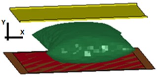
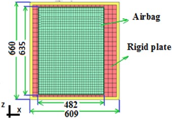
The car dashboard is modeled as the rectangular thin plate using a MAT_RIGID material and the degrees of freedom are constrained in all the directions. It is assigned the similar properties of thermoplastic polymer for contact purposes. The porosity of the fabric is assumed zero. The Nitrogen gas is taken for inflating the airbag. The example on which we perform the study is a typical passenger side airbag. The geometric details have been measured from a commercially available airbag. The initial state of the airbag is a closed rectangular whose sides are to be finished to 482×635 mm2, and is shown in Fig. 4. In these simulations, we also supposed no heat transfer and that the inflating gas behaves as an ideal gas with constant specific heats. Airbag mesh is generated in Ansys® Finite Element Software. It is consisting of 2832 elements and 2875 nodes in the airbag mesh. Quadrilateral elements are used for airbag mesh. Contact type 37 of Lsdyna® software is used for defining the contact between airbag mesh and rigid plates. This contact type is between node and surface. In the simulation, the pressure generated by the gas is then uniformly applied to the internal surface of the airbag fabric. In the simulation there will be an airbag surface and gas that fills up the inside of this surface.
Fig. 3a) Isometric view of squeezed airbag using a rigid impactor with Lloyd EZ20 machine, b) finite element mesh of the airbag and the rigid wall
a)
b)
Table 1Material properties of airbag and rigid plate used in FE simulations
Materials | Airbag | Rigid plate |
Density of fabric [kg/mm3] | – | 2.690E-06 |
Young’s modulus [GPa] | 2.5 | 70.30 |
Poisson’s ratio | 0.345 | 0.30 |
Shear modulus [GPa] | 6.9 | – |
3. Simulation of squeezed airbag
Fig. 4 shows the different steps of the deploying airbags test simulation at different time points. Due to the fact that only 11ms are simulated, the airbag is fully inflated as can be seen in Fig. 4. From the Figures, it can be seen that the airbag module cover opens fully, as close to reality. The increasing of volume is coming mainly from the gas flow. The triggering time of airbag is crucial to evaluate an overall performance of the airbag in a crash event. Fig. 5 shows both simulation states of squeezed airbag. Examining of numerical results shown in Fig. 5, the airbag was less protective when occupant distance was below 40 cm. At these distances, compression with airbag was approximately 80 % higher than first case. An ideal scenario of a rigid plate getting impacted into an airbag after it gets fully inflated could not be achieved in the second configuration of the airbag. In fact, in the second case, it was found that the airbag could not get sufficient space to inflate properly. This can unfortunately render the airbag ineffective, as shown in Fig. 5.
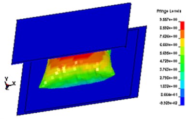
Fig. 6 shows the 3D simulation for squeezed airbag in two situations: airbag fully or partially inflated. The results of first configuration were encouraging compared to the second configuration of the airbag module. A very high internal operating pressure will lead to rebound of the occupant, whereas a small pressure will render the airbag ineffective in restraining the passenger. Fig. 6 shows also that the airbag in the first case absorbed maximum of 84 % kinetic energy of the rigid plate, i.e. the rider’s head whereas in the second case, airbag absorbed only 25 %.
Fig. 4Airbag deployment at t= 11 ms
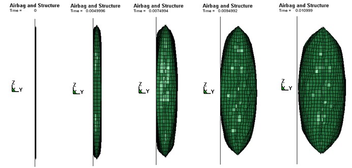
Fig. 5Simulation states of the squeezed of the airbag
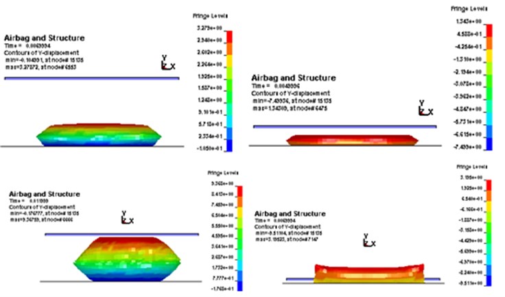
Fig. 6Simulation of squeezed airbag: a) airbag fully inflated, b) airbag partially inflated
a)
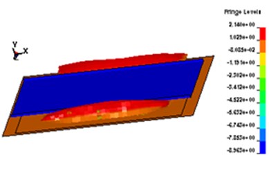
b)
4. Conclusions
This study has employed the FE method to explore collision phenomena. Specifically, this study has investigated the dynamic response of the rigid plate in a crash event. The vehicle occupant’s head replaced by rigid plate has been assessed numerically. The results first has allowed us to show that airbag has been modeled correctly with a proper filling of the gas flow. Predictions for pressures are similar once the airbag has deployed. The numerical results of the squeezed airbag deployment shown that the FE method is also a promising method for simulating of impacted airbag during crash test.
References
-
Marklund P. O., Nilsson L. Optimization of airbag inflation parameters for the minimization of out of position occupant injury. Computational Mechanics, Vol. 31, 2003, p. 496-504.
-
Soongu H. A study on the modelling technique of airbag cushion fabric. SAE 2003-01-0512, SAE World Congress, Detroit Michigan, 2003.
-
Yoganandan N., Pintar F. A., Zhang J., Gennarelli T. A. Lateral impact injuries with side airbag deployments – a descriptive study. Accident Analysis and Prevention, Vol. 39, 2007, p. 22-27.
-
Gabauer D. J., Gabler H. C. The effects of airbags and seatbelts on occupant injury in longitudinal barrier crashes. Journal of Safety Research, Vol. 41, 2010, p. 9-15.
-
Bankdak F. A., Chan P. C., Lu Z. An experimental airbag test system for the study of airbag deployment loads. International Journal of Crashworthiness, Vol. 7, 2002, p. 129-161.
-
Bedard M., Guyatt G. H. The independent contribution of driver, crash and vehicle characteristics to driver fatalities. Accident Analysis and Prevention, Vol. 34, 2002, p. 717-727.
-
Pei J., Yuan S. Q., Yuan J. P. Numerical analysis of periodic flow unsteadiness in a single-blade centrifugal pump. Science China Technological Sciences, Vol. 56, 2013, p. 212-221.
-
Cao Y. H., Wu Z. L. Numerical simulation of aerodynamic interactions among helicopter rotor, fuselage, engine and body of revolution. Science China Technological Sciences, Vol. 57, 2014, p. 1206-1218.
-
Ruff C., Jost T., Eichberger A. Simulation of an airbag deployment in out-of position situations. Vehicle System Dynamics, International Journal of Vehicle Mechanics and Mobility, Vol. 45, 2007, p. 953-967.
About this article

