Abstract
Vehicle driving safety is the urgent key problem to be solved of vehicle independent development while encountering emergency collision avoidance with high speed. And it is also the premise and one of the necessary conditions of vehicle active safety. A new technique for vehicle handling inverse dynamics which can evaluate the emergency collision avoidance performance is proposed. Firstly, the steering angle input of 3-DOF vehicle mode is established. The steering angle input imposed by driver is the control variable, and accurately tracking the expected path was the control object. The optimal control problem can be converted into a nonlinear programming problem while using the state variables conversion, which was solved by the sequential quadratic programming (SQP) algorithm. The results show that vehicle can well track the expected path in high speed.
1. Introduction
On the basis of the known model and vehicle response, vehicle handling inverse dynamics can anti-obtain the allowed driver control inputs. Then it analyzes what kind of manipulation is the safest and fastest, the most easily accepted by most drivers. It is also known as the “inverse problem” of vehicle handling dynamics [1], and belongs to mechanics “dynamic load identification” [2]. Vehicle handling inverse dynamics method computes the control inputs that the driver applied to the vehicle by specifying the handling performance, and compares to the maneuverability of the cars in the most effective way. Handling performances include precisely to achieve a given state variable [3-4], to accurately track the given path [5-8], and to pass the given path in the shortest time in the case of without departing from the path boundary [9-11]. The second case is the problem to be studied in this paper.
Path tracking always makes the vehicle travel along a desired path, while ensures the vehicle safety and comfort. The control layer of path tracking controller operation includes path tracking control, speed tracking control, logic components control, emergency management, the implementing agencies control and many other modules and components. Path tracking control is the core, and currently the most studied problems. With science and technology development and the depth research of operation controller for path tracking, many successful control methods have appeared: fuzzy control method, PID control method, optimal control method, and neural network method, etc. [12-15]. As the vehicle is a very complex nonlinear dynamical systems, it is difficult to establish a precise mathematical model, which requires control methods cannot be too dependent on the accurate mathematical model. In this paper, the car path tracking controller based on fuzzy control method is designed. This control method is suitable for the object which is difficult to establish accurate mathematical model, and it is used to control the vehicle path tracking. Finally, the simulation results of the control methods are shown.
2. 3-DOF vehicle dynamic model
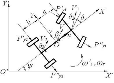
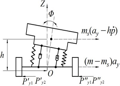
In this paper, automotive linear three degrees of freedom angle input model including roll degree of freedom is used. Vehicle sports state coordinates are shown in Fig. 1. Fig. 1(a) is the top view of vehicle motion, and Fig. 1(b) is the rear view of vehicle motion.
Fig. 1Vehicle sports state coordinates graph
a)
b)
Vehicle motion state response is represented by three generalized coordinates: yaw angle , sideslip angle , car body side angle . Let automobile state vector , is the yaw rate, is the roll angular speed. is the steering wheel angle, the front wheel angle , is the steering gear ratio. The state equation of the car is obtained by the force balance equation:
where, , and:
The parameters in Eq. (1) are defined in Reference 1.
3. The vehicle’s optimal control model for three degrees of freedom angle input
In this paper, the optimal control theory is used to solve in vehicle handling inverse dynamics while encountering emergency collision avoidance. In order to simplify the problem, the driver control input is regarded as the ideal one without the effect of driver’s forward-looking, the neural response lag and steering response lag. The control variables are selected as the steering wheel angle . Because of considering the path tracking, the driver’s control burden, the effects of sideslip and the dangerous of overturn synthetically, the ideal path tracking performance index is:
where, , is the initial time and the end time; is the ideal path tracking for collision avoidance; is the standard threshold value of path tracking error, it takes 0.3 m in this paper; is the standard threshold value of steering angle, it takes 600° in this paper; , is the side force of the front and the rear wheel; , is the vertical load of the front and the rear wheel; , 1, 2; is the standard threshold value of , it takes 0.3 in this paper; is the standard threshold value of vehicle roll angle, it takes 3° in this paper. The state variable of vehicle model is:
From the Eq. (1), the state equations can be expressed as that:
The condition need to be met in the terminal time on vehicle sport state:
In addition, the control variables of steering angle input need to meet the boundary condition due to the limit of driver’s physiology:
where, , is the upper and the lower boundary of the steering angle input, it takes the limit of the steering angle input ±600° in this paper.
4. The transformation of state variables
For the terminal time of the above optimal control problem is not fixed, in order to facilitate the solution, utilize the unitized longitudinal displacement variable to transform the state variables. Above problem is transformed into an optimal control problem of fixed terminal time [16].
Unitized longitudinal displacement variable:
where, is the longitudinal displacement of the initial motor sports; is the longitudinal displacement of the final motor sports.
Derivate of time for Eq. (6) and combine with Eq. (3):
Let the state variable . According to the Eq. (7), the performance index Eq. (2) transforms to:
where, .
At this time, the state equation Eq. (3) will transform to that:
It needs to meet the boundary conditions for the optimal control problem after transforming the state variables;
1. ;
2. .
Finally, use the discrete element theory to transform to be the finite dimensional nonlinear programming problem, and solve it with the sequence quadratic programming (SQP).
To simulate the vehicle in an emergency avoidance condition, the ideal road input is double lane (two yield). Meanwhile, double lane is the typical road model commonly used in evaluating vehicle handling stability evaluation. The road trace takes the actual road centerline trajectory.
5. The path tracking simulation results
This paper is about a vehicle path tracking simulation test, using Matlab/Simulink to establish the computer simulation model. It chooses the road model of double lane and achieves the accurate tracking on a given path to control linear three degrees of freedom vehicle system with the optimal control algorithm.
To simulate the vehicle’s collision avoidance with high speed and reflect the steering performance truly when the vehicle is avoiding, this paper takes the avoidance path of the double lane that model mentioned above. Model one and model two are referred to the Table 1.
Table 1Simulation models parameters
Parameter name | Symbol | Dimension | Model 1 | Model 2 |
Vehicle Quality | kg | 1685 | 1500 | |
Suspension quality | kg | 1365 | 1180 | |
Centroid to the front wheelbase | m | 1.185 | 1.17 | |
Centroid to the rear wheelbase | m | 1.283 | 1.195 | |
Front suspension roll stiffness | N·m/rad | 60548 | 60548 | |
Rear suspension roll stiffness | N·m/rad | 32732 | 32732 | |
Moment of inertia around the axis | kg·m2 | 2280 | 1800 | |
Moment of inertia around the axis | kg·m2 | 960 | 780 | |
Inertia | kg·m2 | 0 | 0 | |
Roll angle damping of the front suspension | N·m·s/rad | 3430 | 3430 | |
Roll angle damping of the rear suspension | N·m·s/rad | 3430 | 3430 | |
Front effective cornering stiffness | N/rad | 40266 | 40021 | |
Rear effective cornering stiffness | N/rad | 75092 | 74648 | |
Roll arm | m | 0.46 | 0.46 | |
Steering gear ratio | none | 24.9 | 24.9 |
Two vehicle models shown in Table 1 have simulation of double lane avoidance path tracking. Let the speed of vehicle 80 km/h. The vehicle path tracking simulation results are as follows.
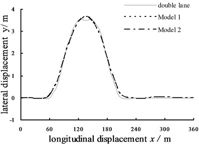
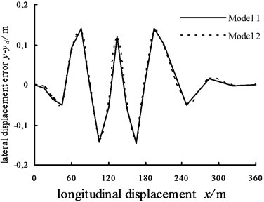
Fig. 2(a) is the lateral displacement simulation results of double lane avoidance path tracking when two vehicle models are at high speed. As the figure shown that two vehicle models are closely matched to the desired avoidance path at high speed during the whole motor process. In addition, the absolute error of actual lateral displacement and avoidanc path of tracking is shown in Fig. 2(b). The max error of model one in longitudinal displacement of 165 m is 0.1474 m. Likewise, the max error of model two in longitudinal displacement of 165 m is 0.1390 m. The max error of the model one is slightly larger than the model two. Thus it can be seen that actual lateral displacement of two different vehicle models has little difference, and it has small absolute error when the vehicle is tracking the avoidance path. Consequently, the optimal control methods used in this paper have the better avoidance at high speed.
Fig. 2Double lane path tracking simulation results (u= 108 km/h)
a) The lateral displacement simulation results
b) The absolute error of lateral displacement
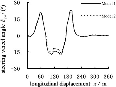
c) Steering wheel angle simulation results
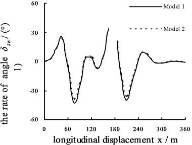
d) The rate of steering wheel angle simulation results
Fig. 2(c) is the steering wheel angle simulation results, the steering wheel angle gets up to the peak when the longitudinal displacement is in 60 m, 105 m, 150 m and 195 m. The steering wheel angle of the model one is larger than the model two; Fig. 2(d) is the rate of steering wheel angle simulation results, the amplitude is lager when the longitudinal displacement is in 75 m, 120 m, 165 m and 210 m. The driver has high level of busyness, and the model one’s rate of steering wheel angle is faster than the model two’s. As the rate and the angle of steering wheel shown that, the amplitude of model one is larger than the model two totally, which the driver in model one has heavy control burden.
6. Conclusions
This paper presents a research method on vehicle handling inverse dynamics based on optimal control while encountering emergency collision avoidance. The method uses steering angle input vehicle dynamic model for three degrees of freedom and establishes optimal control model for handling inverse dynamics. Transform the optimal control problem to a nonlinear programming problem and solve the transformed nonlinear programming problem with the method of sequence of quadratic programming. Therefore, optimal control can be an effective control method in the process of vehicle path tracking control, and has a wider application value and prospect in applying in vehicle path tracking control.
References
-
Zhang Lixia, Zhao Youqun, Pan Fuquan Application of optimal control to vehicle handling inverse dynamics. Journal of Basic Science and Engineering, Vol. 16, Issue 1, 2008, p. 73-78.
-
Liu H., Han X., Jiang C., et al. Dynamic load identification for uncertain structures based on interval analysis and regularization method. International Journal of Computational Method, Vol. 12, Issue 8, 2011, p. 667-683.
-
Andreasson J., Bunte T. Global chassis control based on inverse vehicle dynamics models. Vehicle System Dynamics, Vol. 44, 2006, p. 321-328.
-
Cho Jeongho, Principe Jose C., Erdogmus Deniz, Motter Mark A. Modeling and inverse controller design for an unmanned aerial vehicle based on the self-organizing map. IEEE Transactions on Neural Networks, Vol. 17, Issue 2, 2006, p. 445-460.
-
Majura F., Selekwa, Jonathan R. Nistler Path tracking control of four wheel independently steered ground robotic vehicles. 50th IEEE Conference on Decision and Control and European Control Conference, Orlando, FL, USA, 2011, p. 6355-6360.
-
Amir Ali Janbakhsh, Reza Kazemi A new approach for simultaneous vehicle handling and path tracking improvement through SBW system. ASME 10th Biennial Conference on Engineering Systems Design and Analysis, Istanbul, Turkey, 2010, p. 267-276.
-
Hatwal H., Mikulcik E. C. Some inverse solutions to an automobile path-tracking problem with input control of steering and brake. Vehicle System Dynamics, Vol. 15, Issue 2, 1986, p. 61-71.
-
Hattori Y., Ono E., Hosoe S. Optimum vehicle trajectory control for obstacle avoidance problem. IEEE/ASME Transactions on Mechatronics, Vol. 11, Issue 5, 2006, p. 507-512.
-
Zhang Lixia, Zhao Youqun, Song Guixia, et al. Research on inverse dynamics of vehicle minimum time maneuver problem. China Mechanical Engineering, Vol. 18, Issue 21, 2007, p. 2628-2632.
-
Sharp R. S., Peng H. Vehicle dynamics applications of optimal control theory. Vehicle System Dynamics, Vol. 49, Issue 7, 2011, p. 1073-1111.
-
Velenis E., Tsiotras P. Minimum-time travel for a vehicle with acceleration limits: Theoretical analysis and receding-horizon implementation. Journal of Optimization Theory and Applications, Vol. 138, Issue 2, 2008, p. 275-296.
-
Kelly A. A Feedforward Control Approach to the Local Navigation Problem for Autonomous Vehicles. CMU Robotics Institute Technical Report, 1994, p. 1-37.
-
Aracil J., Heredia G., Ollero A. Global stability analysis of fuzzy path tracking using frequency response. Engineering Applications of Artificial Intelligence, Vol. 13, 2000, p. 109-119.
-
Fraichard T., Garnier P. Fuzzy control to drive car like vehicles. Robotics and Autonomous Systems, Vol. 34, 2001, p. 1-22.
-
Wang Junmin, Steiber Joe, Surampudi Bapiraju Autonomous ground vehicle control system for high-speed and safe operation. American Control Conference, Washington, USA, 2008.
-
Sridhar J., Hatwal H. Comparative study of four-wheel steering models using the inverse solution. Vehicle System Dynamics, Vol. 21, Issue 1, 1992, p. 1-18.
About this article
This work is partially supported by the National Science Foundation of Jiangsu University of Technology (Grant No. KYY14041) and Policy Guidance Program (Collaboration) – Prospective Joint Research Project (BY2015028-02).
