Abstract
Being a part of a coastal ± 500 kV DC filter converter station, the suspension steel frame is studied in this paper on the field of strong wind induced vibration. In order to analyze the characteristics of the structure, the response of the suspension steel frame under fluctuating wind load is analyzed by FE method. The study is significant on the area of design and maintenance.
1. Introduction
A ±500 kV converter station located in the eastern coast. The DC filter suspension steel frame in its cross-bearing bear a load of 33 tons. Thus, effectively assess the dynamic response of the DC filter suspension steel frame under the natural strong winds is essential for its safe operation.
In this paper, the simulation of fluctuating wind is obtained by Deodatis’s harmonic synthesis method [1]. Based on the characteristics of the natural wind field, this paper studies the random vibration of the suspended beam of the DC filter of the converter station under natural wind load.
2. Finite element model of DC filter of the converter station
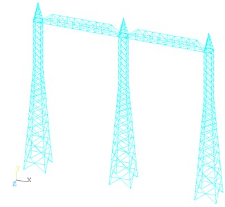
The beams are modeled by finite element method, and the beam element is used to simulate the main material, sub-material and auxiliary material of the truss. The orientation of the angle steel is simulated reasonably by introducing the directional joints. Both ends of the beam support nodes are simulated as hinges. The steel frame of the converter station is shown in Fig. 1, and the whole finite element model of the steel frame of the converter station is shown in Fig. 2.
Fig. 1Steel frame of converter station
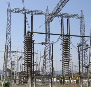
Fig. 2The whole finite element model of the steel frame
3. Simulation of fluctuating wind
In order to analyze the wind-induced vibration response of suspended steel frame under fluctuating wind load, Monte Carlo method was used to generate the fluctuating wind speed time history samples. In the real atmospheric boundary layer turbulence wind field, fluctuating wind speed is not only a function of time, but also changes with the spatial position (, , ). It is a so-called univariate four-dimensional (1V-4D) random field. The fluctuant of natural winds can be approximated as stationary Gaussian stochastic processes for all states. (1V-4D) random field can be treated as a multivariate one-dimensional (nV-1D) stochastic process if the wind field is considered as the sum of the random storms at every discrete points. In this paper, the fluctuating wind speed simulation is carried out by using the harmonic synthesis method proposed by Shinozuka and Deodatis. Harmonic synthesis is a traditional method of simulating random process samples by spectral decomposition and triangular series superposition. Harmonic synthesis of the basic method described below[2].
Considering a zero-mean one-dimensional n-variable stationary Gaussian stochastic process ( 1, 2, ..., ), the cross-correlation and cross-spectral density matrices. And the elements of the cross-correlation function matrix have the following relationship with the elements of the cross-spectral density matrix:
Define the Cholesky decomposition matrix with as , as shown below:
where matrix is the lower triangular matrix; is the complex conjugate transpose of . is the complex phase angle of , as shown below:
According to the research of Shinozuka and Deodatis, the random fluctuating wind speed satisfying all states can be generated according to the following formula:
where is a double-index frequency, defined as:
The use of FFT technology can greatly reduce the amount of wind field simulation, increase the computational efficiency. According to Deodatis’s derivation, the formula can be rewritten as follows:
where is the remainder of , 0, 1,…,. is given by the following equation:
The parameters of the wind field are as follows: the reference wind speed is 10 m, the surface roughness height 0.05 m (close to the landform type B), and the Von Karman constant is 0.4. Wind direction fluctuating wind speed from the power spectrum using the proposed load structure of the proposed Davenport wind spectrum, its form is as follows [3]:
Using the method above, the fluctuating wind speed time histories of the main nodes of the truss structure are simulated respectively. There are 20 analogue points in the structural system. Taking 20 m/s and 30 m/s as reference wind speed, considering the influence of wind profile, the lower chord of the truss is 27 m away from the ground. According to the specification, it is class B wind field, and the thrust is 10 m Wind speed U10 is 17.1 m/s, 25.6 m/s respectively.
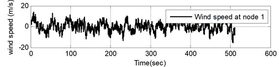
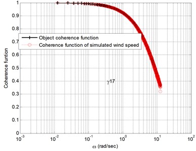
Fig. 4 shows the simulation results of three typical fluctuating wind velocities at an average wind speed of 30 m/s. Fig. 5 show the comparison of the self-power spectrum and the target spectrum of the simulated fluctuating wind speed at typical locations. Simulated wind speed time-course and the target is more consistent. With the increase of the spatial distance, the first and the spatial correlation of fluctuating wind velocity weakened by increasing distance. The simulation of the fluctuating wind speed time series basically reflects the characteristics of the autocorrelation and coherence function, which shows the correctness of the simulation results.
Fig. 3Fluctuating wind velocity samples at nodes 1, 2 and 7 (U= 30 m/s)
4. Wind-induced random vibration analysis of the beam
The calculation of wind-induced dynamic response needs to determine reasonable structural damping. The damping of the structure is usually expressed in the form of Rayleigh damping according to the mass matrix and the stiffness matrix [5]:
In the formula, the relationship between the Rayleigh damping coefficient and the structural modal damping ratio can be described [5]when only the two modes m and n are considered:
where and are the circular frequency and damping ratio for the mth-order mode, and are the circular frequency and damping ratio for the th-order mode. When more modal damping ratios are required, the damping coefficient can be minimized by Two-fold fit:
Fig. 4Comparison of self-power spectrum and target spectrum of simulated fluctuating wind velocity at node 1
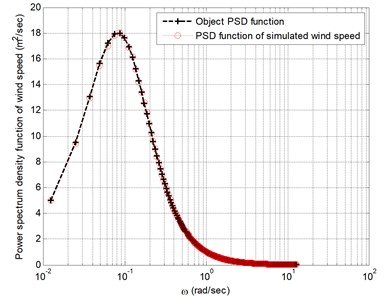
Fig. 5Comparison between the coherent function and the target value of simulated fluctuating wind speed at node 2
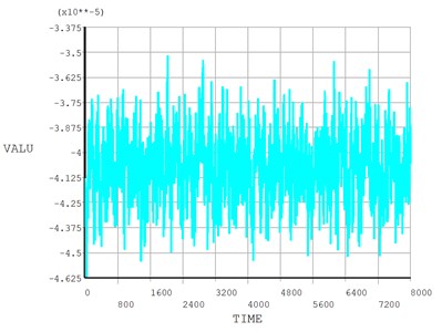
Transient analysis is performed using the appropriate integration time step after obtaining the Rayleigh damping coefficient. The displacement time-history curves of node 1 are shown in Fig. 6, respectively. From the time-history curve, it can be seen that the amplitude of random vibration of frame beam is relatively small, the maximum amplitude of vibration is 3.39×10⁻⁴ m, and the beam of steel frame is not sensitive to fluctuating wind load.
Fig. 6Time response curve of node 1 random wind-induced vibration
5. Conclusions
Simulation of the fluctuating wind of the beam in the suspension of the DC filter was carried out by using Deodatis’s harmonic synthesis method. In order to study the random vibration under the natural wind load, the wind speed time history curve of the frame beam is obtained, which makes a point of the technical reference for the engineering design and maintenance of the cross beam of the DC filter of the converter station.
In this paper, only the beam of the steel frame is analyzed without considering the wind load of the frame column, the wind-induced vibration of the steel frame as a whole structure need to be studied in the future.
References
-
Ouyang Kejian Multi-factor Analysis of Aerodynamic Rational Function and Flutter Stability. Hunan University Doctoral Dissertation, Hunan University, Changsha, 2011.
-
Deodatis G. Simulation of ergodic multivariate stochastic processes. Journal of Engineering Mechanics, Vol. 122, Issue 8, 1996, p. 778-787.
-
Davenport A. G. The application of statistical concepts to the wind loading of structures. In: Proceedings of Institute of Civil Engineers, Vol. 19, 1961, p. 449-472.
-
Vickery B. J. Load fluctuations in turbulent flow. Journal of the Engineering Mechanics Division, Vol. 94, 1968, p. 31-46.
-
Clough R. W., Penzien J. Dynamics of Structures. Third Ed., Computers and Structures, Inc., USA, 1995.
About this article

