Abstract
This paper is focused on the CFD numerical simulation of flutter characteristics of the wide-body flat steel box girder of Chongqing Cuntan Yangtze Bridge. The specific influence on the aerodynamic performance and flutter critical wind velocity have been studied by setting different railing ventilation rates. The results show that: the subsidiary structures of the main beam have an adverse effect on the stability of bridge flutter. The ventilation rate of the railings affects the flutter derivatives and the critical wind speed of the flutter.
Highlights
- flutter derivatives numerical simulation
- bridge railing ventilation rate
- auxiliary structures
1. Introduction
With the emergence of long-span bridges, lightweight and softness have become the development direction of the bridge structures, and the aspect ratio of bridges has also increased. Therefore, flat steel box beams are widely used in long-span cable-stayed bridges and suspension bridges. But the effect of wind on the bridge is increasingly sensitive as the aspect ratio increases. The bridge becomes unstable and eventually leads to destruction due to the aerodynamic forces created by the flutter, so it is necessary to study the flutter characteristics of the wide-body flat steel box girders.
In recent years, many scholars have studied the flutter characteristics of long-span bridge structures. Xinda Bo et al. [1] obtained the influence of the flutter stability of the long-span bridge on rainfall by analyzing the fluttering critical wind speed and flutter derivative under different rain intensities. Long Xiong et al. [2], based on considering the static wind effects, used state-space methods to achieve the flutter three-dimensional vibration analysis of long-span bridges. Li Cuijuan [3] proposed that the torsional stiffness of long-span suspension bridges can be significantly improved by setting the cross slings. Birch et al. [4], based on the one-third force coefficient, gave the parameter , which can quickly evaluate the bridge flutter stability. Tao Shibo [5], based on firefly algorithms, is calculated with the quantum genetic algorithm, crossover and mutation combined to give a mixed firefly algorithm. Xiajin Lin et al. [6] combined two-dimensional and three degree of freedom flutter analysis method to study the influence of the upper and lower combined central stabilizing plates on the flutter characteristics of the box girder of the cross-sea suspension bridge. Xufu You et al. [7] proposed an improved random search algorithm and novel direct method to determine the 18 bridge flutter derivatives. Phan et al. [8], by the two-dimensional bridge deck model experiments, indicated that mechanical control can improve the flutter speed of suspension bridges. Vu et al. [9] pointed out that an accurate Equation by using complex notation is proposed to calculate 18 flutter derivatives of bridge sections. Patruno et al. [10] found a RANS model in predicting the initial flutter speed is very accurate. Sarkic et al. [11] found that the URANS method can efficiently derive bridge flutter derivatives. In the above references, these scholars have studied the flutter characteristics influencing factors of large span bridges and flutter stability evaluation methods.
The wide flat box beam structure has a slenderness ratio because its width is much larger than the height. Compared to span and width, the height is so small that minor modifications to auxiliary structure have effects on bridge flutter performance. By using the method of numerical simulation, this paper studied the flutter characteristics of wide-body flat steel box girder with an aspect ratio of 12, solved the critical flutter wind speed values in the state of the bridge and the construction state, and identified flutter derivatives of flat steel box girder at three different ventilation rates.
2. Numerical model and basic methods
2.1. Engineering background
The Cuntan Yangtze River Bridge is a double-tower and single-span suspension bridge, with the entire length of 1600 m, the main bridge span arrangement (250+880+250) m, the span ratio of 1/8.8, the aspect ratio of stiffening girder of 12, the beam height of 3.5 m, and the beam width of 38 m. The bridge site category is Class B and the deck design elevation is 267.8 m.
2.2. Numerical method
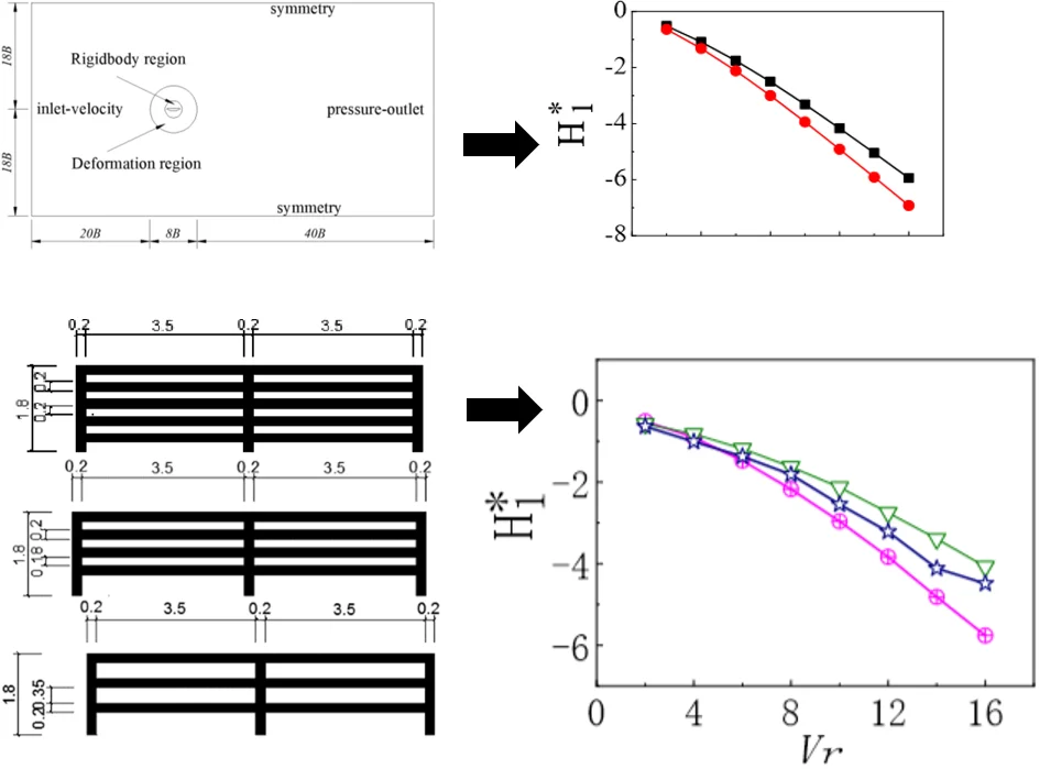
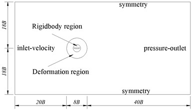
In the numerical simulation, the geometry scale size ratio of the main girder section model is set to 1/60. In the pre-processing code GAMBIT the computational domain is formed. To avoid deformation when the grids move, the computational domain is divided into 4 portions: the outer walls of the bridge model, the rigid body region, the deforming region, and the external stationary region. The specifical dimensions of the numerical model are shown in Fig. 1. Meanwhile, using the FLUENT software for analysis, the calculation adopts the standard - model for turbulence, with a turbulent viscosity ratio of 10, with export taking turbulence intensity of 5 %.
It does not consider energy exchange and temperature variations, taking 4, 8, 12, 16, 20, 24, 28, 32 m/s as inlet velocity, taking 0.01s as time step. According to equation , the converted wind speed can be calculated, taking 2, 4, 6, 8, 10, 12, 14, 16 m/s.
Fig. 1Numerical simulation of flow field region
2.3. Recognition methods of flutter derivatives
To study the bridge flutter characteristics of the wind-induced vibration response, it is necessary to identify the flutter derivatives of the main beam. In the case of ignoring the lateral wind vibration, it is necessary to identify eight flutters in the direction of two degrees of freedom, including vertical and torsional derivatives.
Scanlan [12] introduced a dimension-less aerodynamic derivatives , (1, 2, 3, 4), and obtained the expressions for the lift and moment as:
wherein: , ( 1, 2, 3, 4) are dimensionless number flutter derivatives and about the function of the conversion speed or conversion frequency stream ; is vibration frequency of model, flutter derivatives are affected by morphology of the model; is the amplitude of the torsional direction; is the amplitude of the vertical curve direction; is flow wind velocity; is a full-bridge width; is a half-bridge width:
wherein: is a dimensionless conversion frequency, is the circular frequency of vibration.
This paper uses the state-based forced vibration identification method in numerical simulation calculation. The model performs single-degree-of-freedom vertical bending vibration and single-degree-of-freedom torsional vibration in the flow field by the UDF function. Firstly, let the model do single-degree-of-freedom vertical bending vibration.
The time step is sampled, and the corresponding displacement and speed are and respectively, and the collected data is converted to obtain lift data and torque data . At this time, the unknown quantities in the Eq. (1) are , , , , and the Eq. (1) is converted into the following form:
wherein: , , , are the amount that changes over time.
These are n binary over-determined equations for , , , , which can be solved according to the least-squares principle.
Similarly, the model is subjected to single-degree-of-freedom torsional forced vibration in the flow field, and another four flutter derivatives , , , are obtained.
3. Results and discussions
3.1. Numerical simulation results comparison
For the reliability of the numerical calculation program, numerical calculation results of the plate are compared with Theodorsen’s theoretical solution. The specific dimensions of the analog plate are shown in Fig. 2. The numerical simulation results of the plate are compared with the theoretical solution of Theodorsen, presented in Fig. 3.
Fig. 2Analog flat cross-sectional dimensions (unit: cm)
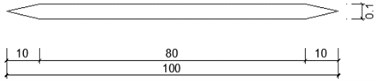
Fig. 3Comparison of plate numerical simulation results with Theodorsen’s theoretical solution (█ theoretical results, ● numerical results)
Seen from Fig. 3, when the converted wind speed is relatively small, the numerical solution is very close to the theoretical solution, then the deviation between the two increases with the increase of the converted wind speed. Therefore, the flutter stability of the structure is affected less by the existing deviation with large wind speed conversion. Further, the numerical solution of plates and theoretical solutions remarkably have a consistent trend with the change of wind speed conversion.
3.2. Influences of auxiliary structures on the flutter derivatives
The change of the aerodynamic shape of the flat steel box girder has a great influence on its aerodynamic response. To explore the specific influence on the aerodynamic performance, the following numerical simulations are carried out by setting different ventilation rate railings to determine the aerodynamic response of the bridge. The ventilation rates of sidewalk railing from small to large are 35.6 %, 45.8 %, 59.8 %, presented in Table 1. In this paper, case 2 is adopted in the preliminary design of the bridge.
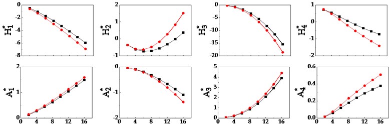
At three ventilation rates, the comparison of the results of the main beam section model flutter derivatives of numerical simulation are shown in Fig. 4.
Table 1Three cases of different ventilation railing of the main beam (unit: m)
Cases number | Sketch | Ventilation rate |
Case 1 | 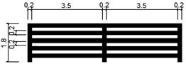 | 35.6 % |
Case 2 | 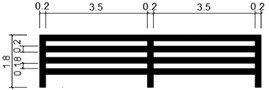 | 45.8 % |
Case 3 | 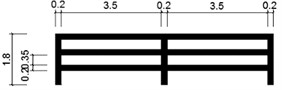 | 59.8 % |
Fig. 4Comparison of numerical simulation results of main beam segment model flutter derivatives (⊕ ventilation rate = 59.8 %, ventilation rate = 45.8 %, ☆ ventilation rate = 35.6 %)
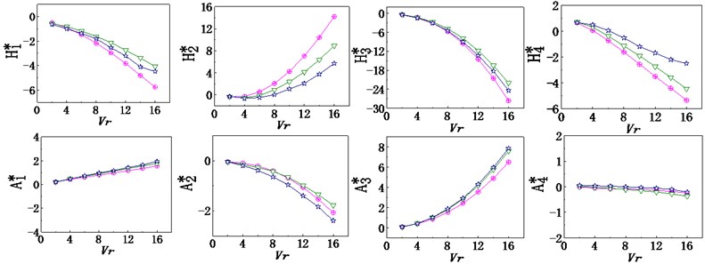
According to Fig. 4:
1) The change of different ventilation rates of railings, set in the wind numerical model, doesn’t influence the general trend of 8 flutter derivatives of the girder model substantially, merely numerical values are different.
2) With the increase of converting wind speed, four important flutter derivatives , , , , associated with vertical curve, and show a significant decline, has a slight rising and presents no significant change. Instead, four important flutter derivatives , , , , associated with the torsion, with the increase of converting wind speed, and show a sharp rise, and show a significant decline.
3) When the converted wind speed is small, the flutter derivative values of the different ventilation rate railings are relatively close; when the converted wind speed is large, the flutter derivative values of the different ventilation rate railings vary widely.
4) As the auxiliary structure of the railing, the flutter derivatives of the main beam segment numerical model, with or without the auxiliary structure, have a large difference, which indicates that the accessory structure has a great influence on the flutter performance.
3.3. Influences of auxiliary structures on the flutter critical wind speed
3.3.1. Calculation method of flutter test wind speed and critical wind speed
According to the literature [13], the design reference wind speed of bridge state at the height of the bridge deck is:
wherein: is design reference wind speed, m/s; is design wind speed at the bridge site, with the standard height of 10 m, the average time from 10 min, 100 years return period, the average annual maximum wind speed, m/s; is a member reference height, m; is coefficient of surface roughness, taken according to the literature [13] Table 3.2.2.
The design wind speed of Construction stage is:
wherein: is the design wind speed for different periods, m/s; is the wind speed coefficient of reproducing, taken according to the literature [13] Table 3.3.1.
Therefore, the flutter test wind speed of bridge state is:
wherein: is employed according to the specification [13] Table 6.3.8.
The flutter testing wind speed of construction state is:
The critical flutter wind velocity of numerical simulation can be obtained by two-dimensional SCANLAN resulting flutter critical wind speed calculation method.
Substituting the calculation results of the flutter derivatives into Eqs. (9-10), the real equations (one quadratic equation) and the imaginary equations (one-element cubic equation) can be obtained, and theoretical solutions of two equations are calculated by the MATLAB program:
wherein: ( 0, 1, 2, 3, 4)is the amount that changes with , , , . (0, 1, 2, 3) is the amount that changes with , , , .
Then calculate the critical wind speed of the flutter according to Eq. (11):
wherein: , is the converted wind speed.
3.3.2. Analysis of results
The critical flutter wind velocity of numerical simulation can be obtained by at which the two-dimensional SCANLAN resulting flutter critical wind speed calculation method. Fig. 5 shows the solution process based on the graphical method. Next, according to Eq. (11), the critical wind speed of flutter is solved. And the calculational results of three cases are presented in Table 2.
Fig. 5Graphic method for solving the critical flutter wind speed of the Cuntan Yangtze River bridge
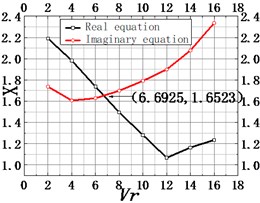
a) Ventilation rate = 35.6 %
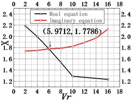
b) Ventilation rate = 45.8 %
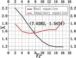
c) Ventilation rate = 59.8 %
Table 2The results comparison of flutter critical wind speed by numerical simulation (unit: m/s)
Section model | Numerical value | Flutter testing wind speed values |
Construction state | 83.02 | 56.96 |
Case 1 | 77.30 | 61.92 |
Case 2 (Bridge state) | 80.49 | 61.92 |
Case 3 | 85.92 | 61.92 |
Comparing numerical simulation values of flutter critical and testing wind speed values, in four cases, the former is larger than the latter, which indicates that design security and flutter stability of the Cuntan Yangtze River Bridge meet the requirements.
And numerical simulation values of flutter critical wind speed in bridge state are smaller than those in construction state, indicating that the subsidiary structures of the main beam have an adverse effect on the stability of bridge flutter.
On the other hand, with the decline of the ventilation rate, the critical wind speed value will decrease. On the contrary, the larger the ventilation rate is, the larger the critical wind speed value of flutter vibration is. Therefore, for improving the flutter stability of the bridge, in the design of the main beam railing, the railing with a large ventilation rate can be adopted as much as possible within the range allowed by the actual conditions.
4. Conclusions
1) 8 flutter derivatives are determined by CFD numerical simulation, whose calculation accuracy is verified by comparing with Theodorsen’s theoretical solution of flat panel. And the accuracy of , , , is significantly higher than , , , .
2) The change of ventilation rates of railings, has no influence on the general trend of 8 flutter derivatives of the girder model substantially, merely numerical values are different. When the converted wind speed is large, the flutter derivative values of ventilation rate railings vary widely.
3) The ventilation rate of the railing can significantly affect the critical wind speed of flutter vibration. With the decline of the ventilation rate, the critical wind speed value will decrease; while the larger the ventilation rate is, the larger the critical wind speed of flutter vibration is.
4) Found from this study: the subsidiary structures of the main beam have an adverse effect on the bridge flutter stability, so subsidiary structures should be carefully set in the design. For improving the bridge flutter stability, the railing with a large ventilation rate can be adopted as much as possible within the range permitted by the specifications.
References
-
Xinda Bo, Wang Liang, et al. Research on stability under the combined effects of wind and rain long-span bridges flutter. China Civil Engineering Journal, Vol. 45, Issue 3, 2012, p. 110-115.
-
Yoong, Liaohai Li, et al. The effect of static wind effect on the meter scale flutter suspension. Huazhong University of Science and Technology (Natural Science), Vol. 42, Issue 16, 2016, p. 44-49.
-
Li Cuijuan, Lee Wing Lok, Tang Maolin, et al. CROSS sling for large main cable suspension bridge across CFRP flutter performance improving effect. China Civil Engineering Journal, Vol. 50, Issue 3, 2017, p. 83-90.
-
Birch Bang, Wang Feng, et al. Bridge flutter stability rapid evaluation parameters and their application. China Journal of Highway, Vol. 29, Issue 8, 2016, p. 92-98.
-
Tao Shibo, Tang Aiping, Huqing Jie, et al. Vibration Analysis Based Hybrid Bridge chatter firefly algorithm. Vibration and Shock, Vol. 36, Issue 4, 2017, p. 144-150.
-
Xiajin Lin, Yang Xin Yong, Ge Yaojun Effect on the combination of the central plate for stabilizing flutter Box properties. China Journal of Highway, Vol. 30, Issue 7, 2017, p. 86-93.
-
Xu F. Y., Chen X. Z., Cai C. S., et al. Determination of 18 flutter derivatives of bridge decks by an improved stochastic search algorithm. Journal of Bridge Engineering, Vol. 17, Issue 4, 2012, p. 576-588.
-
Phan D. H., Kobayshi H. An experimental study of flutter and buffeting control of suspension bridge by mechanically driven flaps. Wind and Structures, Vol. 14, Issue 2, 2011, p. 153-165.
-
Vu T. V., Kim Y. M., Lee H. E. Coupled flutter analysis of long-span bridges using full set of flutter derivatives. KSCE Journal of Civil Engineering, Vol. 20, Issue 4, 2016, p. 1501-1513.
-
Patruno L. Accuracy of numerically evaluated flutter derivatives of bridge deck sections using RANS: effects on the flutter onset velocity. Engineering Structures, Vol. 89, 2015, p. 49-65.
-
Sarkic A., Fisch R., Hoffer R., et al. Bridge flutter derivatives based on computed, validated pressure fields. Journal of Wind Engineering and Industrial Aerodynamics, Vol. 104, 2012, p. 141-151.
-
Scanlan R. H., Tomko J. J. Airfoil and bridge deck flutter derivatives. Journal of Engineering Mechanics, Vol. 97, Issue 6, 1971, p. 1717-1737.
-
JTG/T D60-01-2004 Highway Bridge Design Specifications Wind. People’s Republic of China Ministry of Transportation, China Communications Press, Beijing, 2004.
Cited by
About this article

This research was funded by National Natural Science Foundation of China (NSFC) under the grant numbers 51778093, and the Science and Technology Research Program of Chongqing Municipal Education Commission under the grant number KJZD-K201802501.
