Abstract
The analysis of the reliability of dynamic servo tool rest using traditional methods is inaccurate because the influences of the accuracy of gear machining and assembly are not considered. In this study, a static analysis method for dynamic servo tool rest is conducted considering the influence of accuracy error. Firstly, the working principle of tool rest is analysed, and its working process is divided into two actions, namely, initial positioning and locking. Secondly, the error sources of dynamic servo tool rest are investigated, and the transmission angle error is divided into two kinds, namely, assembly error of shafting and machining error of gear. The static analysis of tool rest is performed by considering the influence of the transmission error of the tool rest. Results show that the assembly, machining and locking forces of the fixed tooth disc of the dynamic servo tool rest have important effects.
Highlights
- A static analysis method for dynamic servo tool rest is conducted considering the influence of accuracy error.
- Main factors that affect the factory accuracy and reliability of the dynamic servo tool rest are identified.
- Fixed tooth disc phase angle error has the greatest influence on the reliability of the tool rest,Which has more important influence on the reliability of tool rest.
1. Introduction
Computer numerical control (CNC) machine tools are the mother machine of the manufacturing industry. At present, the speed, precision and multi-axis linkage of CNC machine tools in China are close to those in the international level, but reliability level gap is still large [1]. Dynamic servo tool rest is a key functional component, its dislocation accuracy greatly affects the reliability due to the complex structure and high requirement for dislocation accuracy [2]. Jia collected a batch of reliability data of CNC tool rest products through one-year field reliability test and determined the characteristics of exponential distribution of time between failures through reliability modelling analysis [3]. Zhang analysed and concluded that the fault process of CNC tool rest conformed to the update process model through reliability assessment, thereby providing a theoretical basis for the reliability assessment [4]. Liu proposed a qualitative analysis and quantitative evaluation method for the reliability of the servo tool rests in the research and development stage based on the PCM-PHM comprehensive model of operation information to effectively evaluate the reliability level of the servo tool rests [5]. SW analysed the reliability prediction of CNC tool rests and predicted the reliability of each CNC tool rest component based on the machine tool part database [6]. Yang constructed a set of reliability test bench that could realise the dynamic and static loads of CNC tool rest in a laboratory environment through the electrohydraulic servo loading unit to carry on the dynamic force loading of the CNC tool rest. To some extent, this can limit access to the failure data cycle under the new test method [7].
The influencing rules of tooth disc positioning accuracy of the dynamic servo tool rest under the influence of error and no error are determined through computer simulation by simplifying the tool rest and establishing the finite element model.
2. Parametric model of dynamic servo tool rest
2.1. Analysis of the gear’s initial error
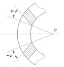
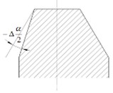
For error analysis (Fig. 1), the plane formed by the median line of the dynamic servo tool rest’s ideal tooth disc surface is defined as the node plane. Tool rest and gear disc coordinate systems are also defined. The symmetrical centre relative to each tooth in the plane of tooth disc are determined, and this point is taken as the origin of the tool rest coordinate system.
Fig. 1Pitch plane of gear plate
2.2. Analysis of angular error
To facilitate differentiation and identification, the subscript is taken as the serial number of each shaft, as the two ends of the shaft, and as the serial number of each gear pair.
The angular error is distributed in the periphery of the gear disc and follows normal distribution. Error of assembly and machining of the gear mainly cause angular errors [8-10].
The angular error caused by gear machining error is:
where is the total deviation of tangential synthesis, is gear dividing circle diameter, and is the gear angular error.
The normal distribution function is used to analyse the working error. Therefore:
where is the standard uncertainty for the angular motion of gears.
The assembly error will cause the gear to jump in the process of rotation, thereby causing the angular error of shafting:
where is the standard uncertainty for radial errors, is the pressure angle, and is the standard uncertainty of angular error.
The sensitive error direction refers to the radial direction of the bearing because the inner and outer rings of the bearing are equivalent to thin-walled parts. As such:
where is the standard uncertainty of coaxiality of axial diameter, is the roundness deviation degree of the axis, is the deviation degree of the bearing relative to its ideal axis, and is the standard uncertainty:
where is the coaxiality of axial diameters at both ends:
where is the difference between the journal and the ideal roundness, and is the relative difference of axis.
The error caused by eccentric connection between gear and shaft is:
where is the gear eccentricity, and is the standard uncertainty of angular motion caused by the eccentric connection between the gear and the shaft.
The angular error of transmission mechanism is:
where is the synthetic standard uncertainty of angular motion of a single gear:
where is the transmission ratio, and is the synthetic standard uncertainty of the angular motion of the transmission mechanism.
3. Distribution parameters of random locking mechanism variables
3.1. Initial position error of tooth disc
The radial, axial, inclination and phase error angles of fixed and locking tooth discs can be determined by decomposing the initial position error of the tooth disc (Table 1).
Table 1Gear plate error parameter
Unit | Fixed tooth discs | Font style | Numbering | |
Radial error | Mm | 50 | ||
° | 270 | |||
Axial error | μm | – | ||
Inclination | 10-3° | |||
° | ||||
Error of phase angle | 10-2° |
3.2. Tooth disc machining error
The inaccurate milling of a cutter in the axial position results in tooth thickness error. Particularly, when the direction of the linear movement of the milling cutter does not coincide with the coordinate system of the tooth disc, the error will be generated. Inaccurately relative inclination of milling cutter will generate tooth shape half angle error (Fig. 2).
Fig. 2Gear plate machining error
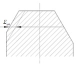
a) Tooth thickness error
b) Tooth error
c) Toothed half-angle error
(a) Tooth thickness tolerance:
where is the equivalent axial run-out tolerance, is the equivalent tooth radial feed tolerance, is the tooth profile angle, and is the standard uncertainty of tooth thickness tolerance.
(b) Tooth alignment error:
where is equivalent helicaland is the measuring range of equivalent helical, is the tooth profile angle, where is the equivalent helical deviation and is the equivalent helical inclination deviation, and is the standard uncertainty of tooth direction error.
(c) Half-angle error of tooth profile:
where is the equivalent tooth profile and is the range of equivalent tooth profile, where is the equivalent profile deviation and, is the equivalent profile inclination deviation, and is the standard uncertainty of half-angle error of tooth profile.
The tooth thickness, tooth direction and half-angle errors of tooth shape can be determined by using Eqs. (10-12), respectively (Table 2).
Table 2Parameters obtained by calculating machining error
Error | Unit | Fixed tooth discs | Moving tooth discs | Locking tooth discs |
μm | ||||
10-2° | ||||
10-2° |
4. Finite element analysis
4.1. Static analysis of error-free gear disc
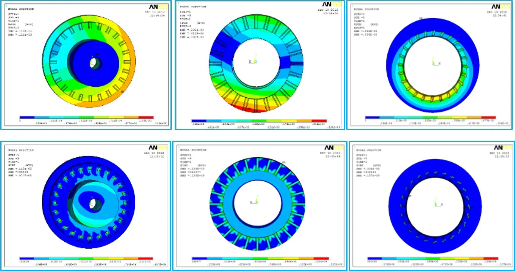
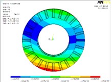
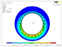
The moving tooth disc and the main shaft are simplified into fixed rigid connections without the role of bolt holes. The errorless tooth disc mesh is hexahedral element. The tooth surface of the locking tooth disc is set as the target surface, and the two other tooth surfaces are the contact surface ‚according to the position connection relation of the three tooth discs. The target element is targe 170, and the contact element is contat 173. A full restraint is applied on the outer circle far from the moving and fixed tooth discs. Then, a uniform pressure load is applied at the connection point between the locking tooth disc and the piston. Equivalent displacement and Equivalent stress diagram are shown in Fig. 3.
Fig. 3Equivalent displacement and Equivalent stress diagram
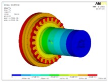
a)Displacement of dynamic tooth disc
b) Displacement of lock tooth disc
c) Displacement of fixed tooth disc
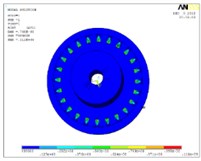
d) Stress of dynamic tooth disc
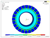
e) Stress of lock tooth disc
f) Stress of fixed tooth disc
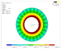
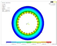
4.2. Statics analysis of toothed disc with error
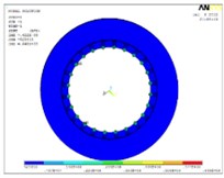
The machining and positioning errors of the tooth disc will affect working performance. When the contact pair is established, the effect is taken into account, and the influence of the positioning error of the tooth disc of the tool holder is introduced to establish the contact pair with the error, and then the solution is carried out, which are shown in Fig. 4.
Fig. 4Equivalent displacement and Equivalent stress diagram
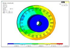
a)Displacement of dynamic tooth disc
b) Displacement of lock tooth disc
c) Displacement of fixed tooth disc
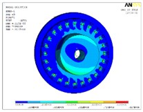
d) Stress of dynamic tooth disc
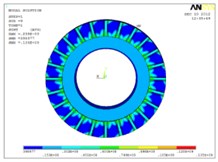
e) Stress of lock tooth disc
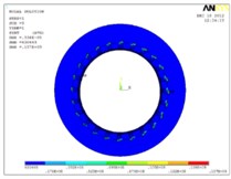
f) Stress of fixed tooth disc
The force on the tooth disc with error is uneven, and the maximum error of the extreme stress distribution can reach 142.28 % based on the static analysis results of the errorless gear in Table 3. Meanwhile, local deformation is also relatively large, and the maximum error of deformation extremum can reach 1371.35 %. Thus, the initial error of tool rest will impact the positioning accuracy of the tooth disc greatly.
Table 3Comparison results of static analysis values
Items | Value of tooth disc without considering errors | Value of tooth disc considering errors | Errors |
Equivalent displacement chart of the complete model | 0.285×10⁻⁴mm | 0.238×10⁻³mm | 735.09 % |
Equivalent displacement chart of dynamic tooth disc | 0.768×1-5mm | 0.113×10⁻³mm | 1371.35 % |
Equivalent displacement chart of the lock tooth disc | 0.285×10⁻⁴mm | 0.238×10⁻³mm | 735.09 % |
Equivalent displacement chart of fixed tooth disc | 0.422×10⁻⁵mm | 0.536×10⁻⁵mm | 27.01 % |
Equivalent stress char of the complete model | 112 MPa | 157 MPa | 40.18 % |
Equivalent stress chart of dynamic tooth disc | 112 MPa | 91.7 MPa | –18.13 % |
Equivalent stress chart of the lock tooth disc | 92.6 MPa | 135 MPa | 45.79 % |
Equivalent stress chart of the fixed tooth disc | 64.8 MPa | 157 MPa | 142.28 % |
5. Conclusions
The conclusions are drawn as follows:
1) Main factors that affect the factory accuracy and reliability of the dynamic servo tool rest are identified.
2) Compared to assembly of fixed tooth disc, processing of tooth disc and operating fluids pressure (locking force) Fixed tooth disc phase angle error has the greatest influence on the reliability of the tool rest, which has more important influence on the reliability of tool rest. Therefore, assembly and processing should be deeply analysed to determine the reliability of weak link. In this manner, the level of reliability of the entire tool rest can be improved.
References
-
Yang Zhaojun, Chen Chuanhai, Chen Fei, et al. Progress in the research of reliability technology of machine tools. Journal of Mechanical Engineering, Vol. 49, Issue 20, 2013, p. 130-139.
-
Wang Xiaohui, Ding Zhi, Liu Baoquan, et al. Modeling of hysteresis for fast tool servo system based on RBF neural network. Journal of Southeast University, Vol. 42, Issue 1, 2012, p. 217-220.
-
Jia Yazhou, Wang Molin, Jia Zhixin Probability distribution of machining center failures. Reliability Engineering and System Safety, Vol. 50, Issue 1, 1995, p. 121-125.
-
Zhang Yingzhi, Shen Guixiang, Xue Yuxia, et al. Fault process for turret systems of CNC lathes with random ending. Journal of Jilin University (Engineering and Technology Edition), Vol. 38, 2008, p. 118-121.
-
Seung Woo Lee, Hwaki Lee Reliability prediction for VDI turret. Journal of the Society of Korea Industrial and Systems Engineering, Vol. 28, Issue 1, 2005, p. 49-54, (in Korea).
-
Kong Xiangzhi, Guo Zhichun Key technologies research of turret reliability experiment. Mechanical Engineer, Vol. 4, 2018, p. 95-98.
-
Yang Zhaojun, Yang Chuangui, Chen Fei, et al. Optimization of the electro-hydraulic servo loading based on least square and SVDUKF algorithms. Journal of Jilin University, Vol. 44, Issue 171, 2014, p. 392-397.
-
Lin Changhong, Zhu Jiacheng The calculation of transmission error of gear. Machine Design and Research, Vol. 38, Issue 8, 2011, p. 10-13.
-
Wu Cisheng Transmission error caused by gear eccentricity error. Journal of Southeast University, Vol. 12, Issue 4, 1982, p. 133-145.
-
Geng Yazhou, Sun Beibei Analysis of gear transmission error of power-driven turret. Machin Building & Automation, Vol. 2, 2018, p. 18-22.
About this article

