Abstract
The authors have been developing a micro spherical ultrasonic motor for a blood vessel endoscope to observe a blood vessel and make a diagnosis. It has two degree of freedom in one joint. The endoscope with the motor enables a doctor to control a camera angle to the affected area on the wall of the blood vessel. Comparing to the conventional endoscopes operated by wire-drive with an optical fiber and wide-angle lens, it has the advantages of rotating the camera with a right angle to the wall and obtain a precise image. In this research, we have developed the prototype motor and showed the characteristics of it.
1. Introduction
Cardiovascular disease caused by hardening of the arteries is a serious disease in the world. In the diagnosis of this vascular disease, inspection method using angioscopy has been attracting attention as a method to observe and to diagnose the lesion directly. There is a problem for angioscopy that it is difficult to observe the lesion in the blood vessel from the front. In this research, the authors developed multi Degree-of-Freedom micro spherical ultrasonic motor using wire stators for angioscopy. The authors have examined the basic characteristics by single-axis experiment and confirmed that rotation speed can be controlled by voltage and frequency. In addition, the authors examined controllability of rotational speed and rotation direction in 2-axis experiment. Consequently, the authors confirmed that rotational speed can be controlled by voltage and rotation direction can be controlled by the ratio of the traveling wave and standing wave of the stator.
2. Wire stator spherical ultrasonic motor
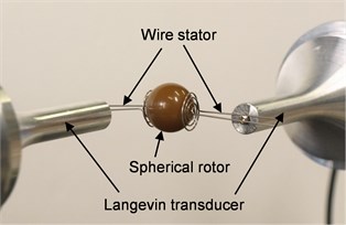
The authors have a spherical motor by use of ultrasonic technology, as shown in Fig. 1 [1-4]. It consists of three circle metals with PZT (piezo electric effect ceramics) and a spherical rotor. It has three rotational degree of freedom in one joint. It shows excellent maneuverability, but it is not small enough for a blood vessel endoscope application. So, we separate the vibration generator from the rotor and reduce the size of it, as shown in Fig. 2(a). The authors call this type of motor a wire stator spherical ultrasonic motor (Fig. 2(b)). The wire stator spherical ultrasonic motor consists of the spherical rotor and spiral wire stators connected to the guide wire.
Fig. 13DOF spherical ultrasonic motor
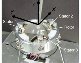
Fig. 2Schematic diagram of micro spherical ultrasonic motor
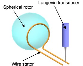
a) Separation of vibration generator from rotor
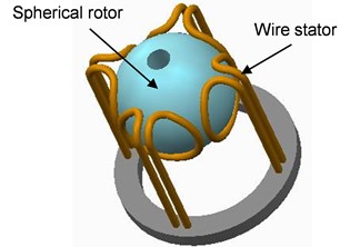
b) Wire stator spherical ultrasonic motor
The principle of it is as follows; applying alternative voltage at the end of guide wire to generate travelling wave (elastic wave), the spherical rotor is driven at the contact area of the rotor and the stators. The contact point of the stator is drawing an elliptical motion which drives the rotor at the top of it by friction. The rotor is rotating in the reverse direction with respect to the elliptical motion’s direction.
3. Design and experiments of prototype of wire stator spherical ultrasonic motor (large model)
The authors have made spiral wire stators shown in Fig. 3. The authors have two kinds of stators; single and multiple spiral coil. In the previous research, the authors have discussed about them and found that a single coil produces small torque due to small contact area, but it shows stable rotation. However, a multiple spiral coil shows large torque due to the many contact points, but it shows deviation of rotational axis direction because a right or left spiral coil has anisotropy. The authors have used multiple spiral coils with a pair of right and left spiral ones because of torque’s first priority. An outer diameter is 12.0 mm and the diameter of the wire is 0.5 mm. The diameter of the rotor (polycarbonate) is 15.0 mm. The end of guide wire is fixed at the top of a Langevin type vibrator.
There are two ways of traveling wave direction; traveling from the center of coil to outside and traveling from outside to the center. In this paper, the authors call the former way a revers driving and the latter way a forward driving. The experimental device is shown in Fig. 4.
Fig. 3Appearance of wire stator
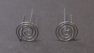
Fig. 4Experiment equipment for 1-axis drive
An applied frequency of Langevin type vibrator is set to be resonant. The authors have measured the velocity from the image of movie camera (30 frames/second), changing applied voltage 5 V to 70 V by 5 V. The results are shown in Fig. 5(a). It shows the increasing of the rotational velocity from 5 V to 40 V and decreasing from 40 V to 70 V. It is because that the wire’s vibration is enlarged and unstable of contact with the rotor as the output of Langevin vibrator is increasing. The same results are obtained in the case of reverse rotation. These results suggest that this motor can be controlled at applied voltage.
The authors have also examined the rotational velocity changing applied frequency around the resonance (24.552 kHz and 24.661 kHz) at applied voltage 40 V. The results are shown is Fig. 5(b). It shows the typical resonant characteristics, that is, it draws steep increasing of rotational velocity and decreasing steeply. The applied frequency may not be suitable for controlling the motor.
Fig. 5Basic characteristics
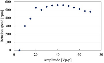
a) Voltage – rotation speed
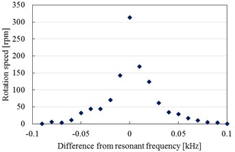
b) Frequency – rotation speed
4. Design and experiments of two degree of freedom wire stator spherical ultrasonic motor
The authors have made experiments of two degree of freedom motor as shown in Fig. 6. It has two sets of wire stators orthogonal each other. It is controlled by applied voltage. The contact force of the rotor and stator is adjusted as one-axis experiments mentioned above. In this experiments, we will discuss eight rotational direction shown Fig. 7 and Table 1.
Fig. 6Experiment equipment for 2-axis drive
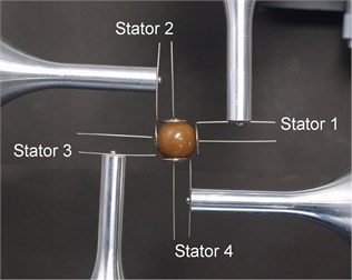
Fig. 7Direction of rotation vector
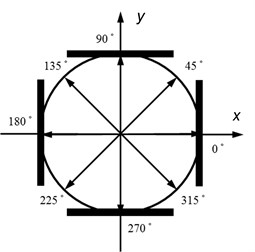
Table 1Relationship between rotation vector and output of each stator
Direction of rotation vector | Stator 1, Stator 3 | Stator 2, Stator 4 |
0° | Forward | – |
45° | Forward | Forward |
90° | – | Forward |
135° | Reverse | Forward |
180° | Reverse | – |
225° | Reverse | Reverse |
270° | – | Reverse |
315° | Forward | Reverse |
4.1. Case of rotation around axes of 45°, 135°, 225°, and 315°
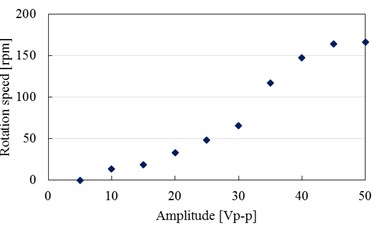
In these cases, each stator is driven by same voltage (reverse or forward) of two pairs of the stators. The authors have changed applied voltage from 5 V to 50 V by 5 V and measured the rotational velocity. The driving frequency is resonant frequencies. The results are shown in Fig. 8. It shows the increase of velocity in accordance with applied voltage. The rotation is stable at applied 50 V, because the rotor is supported firmly from both sides. The rotational axis direction is nearly equal to the direction of the model. The applied voltage as a control parameter shows good controllability.
Fig. 8Voltage-rotation speed characteristics (Forward-Forward)
4.2. Case of rotation around axes of 0°, 90°, 180°, and 270°
In these cases, one stator pair is set to be zero applied voltage. So, the guide wire carry no waves that the stator makes full contact with the rotor to cause large frictional force to prevent rotation of the rotor. In the experiment, the authors could not drive the motor. In order to solve it, the authors have applied standing wave to the stator instead of zero voltage. The standing wave is vibrating up and down at the same position and carrying no waves. It cannot drive the rotor but supporting it with very low frictional force like floating. Applying the standing wave with the same voltage applied to the other pair of stator, the rotor is rotating successfully.
4.3. Control of the rotational axis
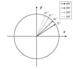
Changing the applied voltage, the authors have controlled the rotational axis direction of the rotor. For an example, the rotational axis direction is moving as show in Fig. 9, when the authors have changed the voltage about the axis stator pair and have set the voltage about axis to be constant. Since the applied voltage difference is not proportional to the difference of the velocity generated on the stator, it is difficult to calculate the rotational direction of the rotor. In the experiment, the voltage around axis is set to be 40 V (full voltage), the authors have changed the voltage around y axis from 40 V to 10 V by 10 V. The rotational axis direction is obtained by the movie (the authors put a marker on the stator). The results are shown in Fig. 10. However, they are against the authors’ anticipation. It is because that the frictional force is also changing, when changing the applied voltage. They have a very complicated relationship. The applied voltage does not show the good controllability.
Fig. 9Changes in rotation vector in the case of reducing output of y-axis direction
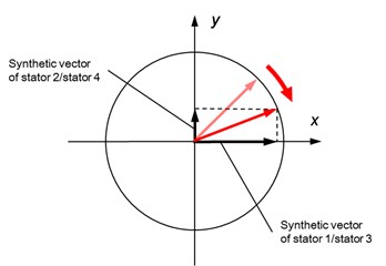
Fig. 10Changes in rotation vector in the case of reducing output of stator 2 / stator 4
4.4. Discussion about control of rotational axis direction
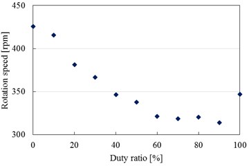
In the experiment, the authors have found that applied voltage is not suitable for controlling the direction of the rotor. Instead of it, the authors have applied PWM (Pulse Width Modulation) to it, that is to say, the authors change the ratio of full voltage (40 V) and zero voltage. The authors’ PWM is slightly different from the conventional one. Fig. 11 shows that PWM wave is input to one end and full voltage traveling wave is input to the other end. The authors have examined one axis velocity control by PWM. The cycle time is 10 ms. The results are shown in Fig. 12. It shows good characteristics. It suggests good method of control for two degree of freedom motor.
Fig. 11Experiment equipment for duty ratio control
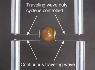
Fig. 12Duty ratio - rotation speed characteristics
5. Conclusions
In this research, the authors have developed a prototype of wire spherical ultrasonic motor. The authors have concluded as follows.
1. The authors have designed and made a wire stator spherical ultrasonic motor.
2. The authors have showed the characteristics of one axis drive of the motor. The applied voltage is good parameter for control of the velocity.
3. The authors have examined the two degree of freedom motor and showed that PWM is a candidate for control of the rotor’s rotational axis direction.
References
-
Takesue N., et al. Position control methods of spherical ultrasonic motor. Proceedings of IEEE/RSJ International Conference on Intelligent Robots and Systems, 2010, p. 3061-3066.
-
Sashida T., Kenjo T. An Introduction to Ultrasonic Motors. Oxford University Press, Oxford, 1993.
-
Purwanto E., Toyama S. Control method of a spherical ultrasonic motor. Proceedings of IEEE/ASME International Conference on Advanced Intelligent Mechatronics, 2003, p. 1321-1326.
-
Mashimo T., Awaga K., Toyama S. Development of a spherical ultrasonic motor with an attitude sensing system using optical fibers. Proceedings of IEEE International Conference on Robotics and Automation, 2007, p. 4466-4471.
About this article

