Abstract
The constructions of ball-type automatic balancing devices with a ball-shaped cross-section in the body are widely known. The specificity of such automatic balancers is the presence of several stable regimes of movement of compensating masses, though the choice of the dimensions of compensating masses and how it influences the operation of an automatic balancer have not been completely clarified issues yet. The given article is devoted to the clarification of the influence of dimensions of compensating masses on working conditions of the automatic balancer.
1. Introduction
The body of the automatic balancer is a torus with a circular raceway in the cross-section of the body [1, 2]. The body of the automatic balancer is fastened concentrically in relation to the rotor axis and at its rotation the compensating masses together with the rotor start to move in circumferential and cross-sectional directions. The acceleration of the compensating masses till the rotor velocity occurs if initial conditions [3] are provided.
There are works [1] which specify that if it is not possible to ensure initial conditions for the compensating masses, they will steadily move inside in relation to the torus-shaped body (unsteady regime of the operation of an automatic balancer) and cause increased vibrations of the rotor. Therefore, this is of interest to determine the impact of dimensions of a compensating mass on the operation of the automatic balancing device.
The purpose of work is to determine necessary initial conditions for a compensating mass to ensure its acceleration till the rotor velocity (stop of the compensating mass in relation to the torus-shaped body of the automatic balancer). This work continues the set of works [1] and is based on experimental researches of a centrifugal machine [4] and a separator [5].
2. Calculation scheme and mathematical model of a rotor with an automatic balancer
The authors of work consider a symmetric vertical rigid rotor on the elastic dissipative suspender and with an automatic balancer fixed symmetrically in relation to the supports. The parameters of the calculation scheme of the rotor system are marked as follows:
– radius of the torus-shaped body of the automatic balancer on the average circumference in the circumferential direction;
– radius of the torus-shaped body of the automatic balancer in the cross-section;
– radius of the compensating mass (ball-shaped body);
– mass of the ball-shaped body (the compensating mass);
– rotor mass;
– static unbalance of the rotor;
and – coefficients of rigidity and viscous damping corresponding to the elastic suspender of the rotor. The body of the automatic balancer is concentrically fixed on the rotor and rotates together with it with angular velocity .
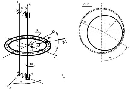
The calculation scheme of the rotor with an automatic balancer is displayed in Fig. 1. In relation to the fixed system of coordinates the rotor together with the body of the automatic balancer makes plane-parallel movement circumscribed by the movement of the rotor axis (coordinates , ). Movement of the compensating mass is circumscribed by two angle coordinates in the flexible system of coordinates (coordinates , ).
Fig. 1Calculation scheme of the rotor with the automatic balancer
The set of differential equations of movement describing the movement of the rotor system with an automatic balancer is given in [1]:
where ,..., – functions depending on the parameters of the rotor system [1]; – coefficient depending on the geometric parameters of the automatic balancer; – a unit force of the safe pressure of the compensating mass on the inner surface of the body of the automatic balancer.
Taking into account that the velocity of the rotor’s rotation is constant (, ), and for the convenience of a numerical solution of the set of equations [1] we will present it in a dimensionless aspect, having expressed the system parameters through the following values:
where – dimensionless time. At the numerical solution of the differential equations we will accept 1 and 1.
The dimensionless force of safe pressure of the compensating mass on the inner surface of the body of the automatic balancer:
The results of the calculation of the set of differential equations are received in the form of dimensionless velocities and coordinates:
3. Research results of the mathematical model
The differential equations of movement Eqs. (1-4) of the rotor system with an automatic balancer were researched with the help of software SPRING [6] which provides a possibility to carry out calculations, both at the working, and at a transient regime of the automatic balancer.
The authors research the influence of the diameter of the compensating mass on the conditions of its acceleration till the rotor velocity. The initial velocity of the compensating mass in the circumferential direction of the body of the automatic balancer was thus defined (at 0, 0, 0, 0, 0, 0, 0, 0) at which its acceleration till the working velocity of the rotor is ensured. The calculation results are given in Table 1. The graphic display of dependence of initial velocity of the compensating mass in the circumferential direction of the automatic balancer on the value relating to the space between the body of the automatic balancer and the compensating mass at various values of the coefficient of rolling friction is given in Fig. 2. The change of the rolling friction is taken within the range: 10-5,…, 3·10-5 m (for a frictionless bearing along hard steel). From Fig. 2 it is clear that the acceleration of the compensating mass is essentially influenced by its dimensions and the coefficient of rolling friction.
Table 1The calculation results
The coefficient of rolling friction 3·10-5 m | ||||||||
0.25 | 0.50 | 1.00 | 2.00 | 2.50 | 2.60 | 2.70 | ||
–0.356 | –0.382 | –0.421 | –0.523 | –0.600 | –0.640 | 1.000 | ||
The coefficient of rolling friction 2·10-5 m | ||||||||
3.00 | 4.00 | 5.00 | 6.00 | 6.50 | 6.70 | 6.75 | 6.80 | |
–0.102 | –0.211 | –0.322 | –0.452 | –0.540 | –0.605 | –0.637 | –1.000 | |
The coefficient of rolling friction 10-5 m | ||||||||
8.80 | 9.00 | 10.00 | 10.50 | 10.60 | 10.75 | 10.83 | 10.90 | |
–0.001 | –0.069 | –0.303 | –0.438 | –0.470 | –0.529 | –0.580 | –1.000 | |
Fig. 2Dependence of initial velocity of the compensating mass in the circumferential direction of the body of the automatic balancer v3 on the value relating to the space between the body of the automatic balancer and the compensating mass e0 at the change of the coefficient of rolling friction k
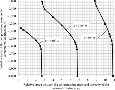
In case of invariable dimensions of the automatic balancing device ( and ) and value of rotor unbalance e it is necessary to ensure quite certain dimensions of the compensating mass . At the reduction of the coefficient of rolling friction for the acceleration of the compensating mass till the rotor velocity it is necessary to reduce the dimensions of the compensating mass (to increase the space between the compensating mass and the body of the automatic balancer).
On the other hand, at the increase of dimensions of the compensating mass (space reduction between the compensating mass and the body of the automatic balancer), it is necessary to increase the coefficient of rolling friction. At the same time, at greater values of the coefficient of rolling friction the amplitudes of rotor oscillations increase. Fig. 3 displays the amplitudes of rotor oscillations at various values of rolling friction and the following parameters of the rotor systems: 0.357; 0.005; 0.005; 2.5; 15; 200. Two values of the rolling friction thus have been taken: in the first case = 10-5 m, and in the second one 3·10-5 m.
Dependence of amplitudes of rotor oscillations towards the axis on the value of the coefficient of rolling friction between the compensating mass and the body of the automatic balancer is shown in Fig. 4. The amplitudes of oscillation towards axis y change in the same way. Fig. 4 displays that at the increase of the coefficient of rolling friction the amplitudes of rotor oscillation also increase.
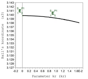
The reason to increase the amplitudes of rotor oscillations is that at the increase of the coefficient of rolling friction because of the increased force of resistance the compensating mass stops further from an optimum place, which can be seen in Fig. 5.
The practical confirmation of the research results is received in [2] where for the acceleration of the compensating masses till the rotor velocity a ball of a smaller diameter was placed in the automatic balancer.
Fig. 31 – amplitudes of rotor oscillations at k= 10-5 m
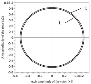
Fig. 4Dependence of amplitudes of rotor 2 – amplitudes of rotor oscillations at k= 3·10-5 m oscillations towards axis x on the value of the coefficient of rolling friction kr=k/r
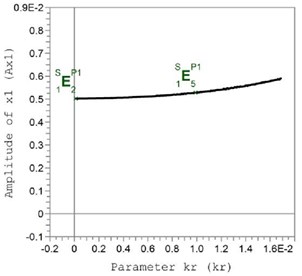
Fig. 5The coordinate of the compensating mass in the circumferential direction x3 depending on the value of the relative coefficient of rolling friction kr=k/r
4. Conclusions
As a result of the carried calculations of the mathematical model of a vertical rotor with concentrically fixed body of the torus-shaped automatic balancer with a circular cross-section on it, it has been found that the acceleration of the compensating mass of the automatic balancer till working velocity of the rotor essentially depends on the dimensions of the compensating mass and the coefficient of rolling friction. Thus, the smaller the dimensions of the compensating mass are (the bigger the space between the body of the automatic balancer and the compensating mass is), the smaller coefficient of rolling friction can be applied to implement the acceleration of the compensating mass. Otherwise, the compensating mass will steadily move inside the body of the automatic balancer, and the rotor axis will oscillate with heightened amplitudes.
References
-
Strautmanis G., Mezitis M., Strautmane V. Model of vertical rotor with a ball-type automatic balancer. Vibroengineering Procedia, Vol. 8, 2016, p. 57-62.
-
Olausson Stefan, Hagglund Anders, Wierzba Paul Cost Effective and Reliable Automatic Balancer for High Speed Applications. Patent 2002/0056338 A1 US, Appl. No. 60/216,152, 2002.
-
Strautmanis G., Grinevich I., Strautmane V. The influence of automatic equalizer and rotor parameters on the ball’s motion mode. Mehatronic Systems and Materials 2014: Selected Papers, Opole University of Tehnology, Poland, Opole, 2015, p. 135-141.
-
Strautmanis G., Jurjevs V., Cokalo V. Veļas mazgājamo mašīnu centrifūgu balansēšanas ierīce. LV Patents, LV 14368 B, 2011.
-
Gorbenko A. N., Radchenko O. P. Some outcomes of vibration experimental exploration of ship centrifugal separator with balls autobalancing device. Aerospace Technique and Technology (Kharkov), Vol. 42, Issue 7, 2003, p. 158-160, (in Russian).
-
Ščukins I., Zakrževskis M., Ivanov Y., et al. Application of software SPRING and method of complete bifurcation groups for the bifurcation analysis of nonlinear dynamical system. Journal of Vibroengineering, Vol. 10, Issue 4, 2008, p. 510-518.
Cited by
About this article

