Abstract
A new seismic isolation system is introduced in this study that utilizes a combination of confined rubber for vertical loading and sliding rings for energy absorption. In this new system, a central elastomeric core is contained between the steel sliding rings. In laboratory testing of the proposed system, it was shown that the steel rings maintained the required vertical stiffness of the system by controlling the lateral deformation of the rubber core. In the lateral motion, the steel rings dissipated energy by sliding on each other under a friction force limited by their small share of the gravity loads. The advantages of the proposed system as compared with the conventional laminated-rubber bearing include increased vertical stiffness and energy absorption capacity as well as ease of manufacturing at a lowered cost.
1. Introduction
One of the seismic controlling approaches is the base isolation procedure. In such a method, the structure is isolated from the ground acceleration [1]. One of the advantages of these systems is shifting fundamental periods of buildings away from the dominant period of strong ground motion. Moreover, they can prepare an additional energy absorbing for reduction of lateral deflection in the isolator, and acceleration response of superstructure. Hence, these mechanisms result in a considerable decrease of seismic damage in the superstructure and its contains by reducing relative displacement of the stories and transmitting acceleration. The seismic isolation systems include elastomeric, sliding or rolling bearings, or a combination of both [1, 2].
The Laminated Rubber Bearing (LRB) system is one of the used systems subjected to many research studies [1, 3, 4]. This system consists of successive thin layers of rubber and steel plates resulting in a large vertical and an appropriate lateral stiffness suitable for earthquake applications [3]. A lead rod located vertically at the center of the system boosts the lateral stiffness for resistance against wind loads and provides for the energy absorption capacity during severe earthquakes. This system is called the Lead-Rubber Bearing or the NZ system, due to its wide application in New Zealand [1, 4]. The energy dissipation mechanism leads to reduction of the lateral displacements. The High Damping Rubber Bearing (HDRB) is a laminated rubber bearing made from high-damping rubber. In this system, the equivalent viscous damping ratio can be increased to 10-20 % [3]. Extensive studies have been performed by Kelly and Konstantinidis [3], Ryan et al. [5] and Kumar et al. [6] on these systems.
The sliding bearings are one of the isolation systems which are very effective in diminishing seismic accelerations in the structures with various fundamental frequencies [2]. The Friction Pendulum System (FPS) is among the mentioned systems where a combination of pendulum action and sliding of bearings is used. This system consists of a wedge sliding on a smooth concave surface. The contacting surfaces are from Teflon and stainless steel [7].
The Electricité De France (EDF) system includes neoprene plates reinforced with steel. At their upper part, a lead-bronze plate is in frictional contact with a steel plate. It has been used in nuclear plants in South Africa [8, 9]. The Resilient-Friction Base Isolation (R-FBI) system was proposed by Mostaghel and Khodaverdian [10]. This system is composed of several stainless steel and Teflon plates consecutively in frictional contact. A rubber core is located at the center of the system. The gravity loads are sustained only by the friction plates. This in turn results in a frictional resistance and produces energy absorption capacity in a lateral motion. The role of the rubber core is producing a restoring force. A steel rod embedded in the rubber core is used to uniformly distribute the lateral displacement between the sliding plates [1]. The Sliding-Resilient Friction (SRF) system is a combination of R-FBI and EDF systems. In this system, a sliding plate has been added to the upper part of the bearing of the R-FBI system to initiate sliding at this part too, under severe earthquakes [11].
Casciati et al. [12] proposed and tested a new base isolation device which consisted of shape memory alloy bars in a sliding system. The super-elastic behavior of SMA bars lead to the reduction of displacement of the bearing, moreover it dissipated energy.
The Roll-N-Cage (RNC) isolation system is made of a stiff rolling pad placed between a pair of upper and lower circular plates, connected by energy dissipating rods. Lateral strength of this system is determined by wind resistance and the system can restore to its original place after a large earthquake [13].
In this paper, a simple Elastomeric-Sliding Isolation system (ESI) consisting of a confined rubber core for vertical load bearing and several steel rings for energy absorption is proposed. The Poisson’s ratio of the rubber is close to 0.5; it is almost an incompressible material [1, 3]. The steel rings surround the rubber core. they prevent the rubber core from bulging by sustaining hoop stresses induced by hydrostatic lateral pressure of the rubber core. This action results in an enlarged vertical stiffness for the system. The limited vertical shortening of the rubber bearing results in a small portion of the vertical load to be transferred to the steel rings. This fact prepares a certain friction capacity for the steel rings. Under large earthquakes, the steel plates slide on each other and dissipate energy in lateral motion. This action controls the amplitude of horizontal displacement at the location of this device. In the current study, performance of the ESI system is tested by cyclic loading against the conventional LRB system.
2. Introducing the samples
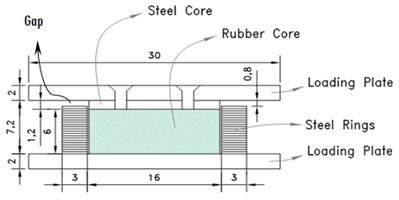
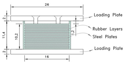
A schematic of The ESI and LRB sample is represented in Fig. 1. In this figure, the upper and lower steel loading plates, the steel rings, the rubber core, and steel core are shown.
Fig. 1Schematic of: a) the proposed ESI sample, b) the LRB sample
a)
b)
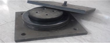
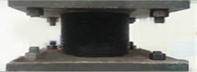
Fig. 2a) the proposed ESI sample, b) the LRB sample
a)
b)
In this study, a prototype of the proposed isolator and an LRB sample acting as the reference system were constructed (Fig. 2). Identical material specifications were selected for the steel and rubber used in producing the above samples. Also, diameter of the rubber and total thickness of the component were taken to be the same. Loading plates were attached to the isolators at their tops and bottoms. The lower loading plate and steel core was attached to the rubber core (layers) on both sides by vulcanization bonding process. The steel core was connected to the upper loading plate using four bolts.
Characteristics of the samples are shown in Table 1 where refers to the diameter of the rubber core that is equal to those of the top steel core plate, and indicate the inner and outer diameter of the steel rings, respectively, demonstrates the thickness of the rubber layers of LRB, and represents the thickness of steel plates (rings) of both prototypes’ components, and shows thickness of the steel core and loading plates, respectively, is considered as number of steel plates of LRB and steel rings of ESI, and as the number of rubber layers of LRB.
Table 1The samples’ characteristics
Isolator type | (cm) | (cm) | (cm) | (cm) | (cm) | (cm) | (cm) | ||
LRB | 16 | – | – | 6 | 0.3 | 14 | 15 | 1.2 | 2.5 |
ESI | 16 | 16.1 | 22 | 6 | 0.3 | 21-22 | 1 | 1.2 | 2.5 |
3. Test set-up
3.1. General
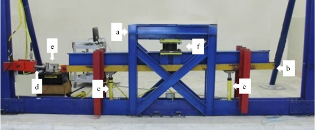
The testing apparatus is shown in Fig. 3. The test set-up includes a rigid frame and a movable beam at the bottom that rests on two vertical hydraulic jacks. The sample is placed between holders which are attached to the rigid frame and to the movable beam to allow for testing under a vertical load. By attaching a third jack horizontally to the tip of the movable beam, testing concurrently in the horizontal direction is also made possible.
Fig. 3The test set-up: a) rigid frame, b) movable beam, c) vertical hydraulic jacks, d) horizontal jack, e) load cell, f) sample
3.2. Testing under compressive force
Testing of the samples under compressive force has been done according to ISO 227621-201, second method, section 6.2.1.5.2.2 [14], described as follows.
Each of the prototypes was subjected first to a vertical load of 50 KN (the design load) and 100 KN (twice the design load). Then, the above loads were increased and decreased up to 30 % in three loading cycles. A certain gap was intentionally provided between the upper loading plate and the first steel ring at the top. The gap was once taken to be 5 mm and then 8 mm, to test its effectiveness in prohibiting direct transfer of the vertical load to the steel rings.
3.3. Design parameters of ESI
The basic assumption for designing the proposed system is that the vertical load is applied directly to the rubber core through the bearing plate. Then, the vertical normal strain is calculated as:
In which is the normal strain in rubber, is the vertical deformation and is the thickness of the rubber core. Resultant of the vertical load applied to the sample is:
where and are vertical load and the normal stress in rubber, respectively, and is the section area of the rubber core at its top. Substituting Eqs. (1) and (2) in the Hook's low for a unit vertical displacement, the vertical stiffness of the system, , is calculated as:
In which is the modulus of elasticity of rubber in compression surrounded by steel rings. It is to be noted that Kelly and Konstantinidis [3] have used the following formula for calculating the vertical stiffness of LRB:
where is the total thickness of rubber and is the modulus of elasticity of the combination of rubber and steel under the vertical load. Comparing Eq. (4) with (3) results in an equation for as follows:
4. Results of the test under compressive force
4.1. The test procedure and results
First, the results for the ESI system with a 5 mm gap at the top are presented. In this test, the number of the steel rings was selected in order to achieve a gap in 5 mm between the loading plate and the first steel ring. A vertical load equal to 50 kN was applied to the ESI sample. This force was increased and decreased up to 30 % during three cycles (see Fig. 4). Values of and were calculated using Eqs. (3) and (5) to be 69.8 kN/mm and 208 MPa, respectively. Then the vertical load was increased to 100 kN and was varied up to ±30 % during three cycles (Fig. 5). This time the measured maximum vertical deflection was 3.84 mm, smaller than the existing gap’s width. The output of and were 83 kN/mm and 248 MPa.
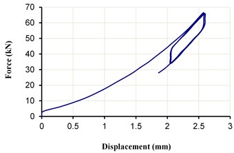
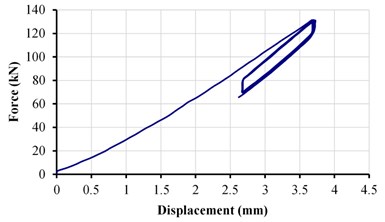
In the next stage, the gap at the top was increased to 8 mm and again the design values of the system were calculated to observe their sensitivity to this parameter. Again, first a vertical load of 50 kN was applied and varied up to ±30 % in three cycles (Fig. 6) which led to 60.4 kN/mm and 180 MPa. Values for a similar test but under a vertical load of 100 kN were 69 kN/mm and 206 MPa and the maximum vertical deflection measured 4.15 mm, which was smaller than the existing gap’s width (Fig. 7).
Fig. 4The load-displacement diagram of ESI with a 5 mm gap, under the vertical load 50±15 kN
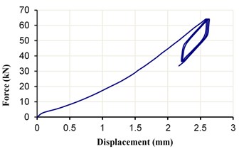
Fig. 5The load-displacement diagram of ESI with a 5 mm gap, under the vertical load 100±30 kN
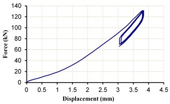
Fig. 6The load-displacement curve of ESI for an 8 mm gap under a vertical load of 50±15 kN
The above results confirm the importance of the gap width.
Now, test results related to LRB (control sample) under vertical load are presented. The LRB sample was undergone a similar series of tests. Under the 50 kN load, 58.2 kN/mm and 174 MPa were determined (Fig. 8). The other cyclic testing under the 100 KN load resulted in 59.6 kN/mm and 178 MPa (Fig. 9). The summary is listed in Table 2.
Fig. 4 to 9 demonstrate both the LRB and ESI systems make hysteresis loops under vertical loadings and unloading. This represents energy dissipation in both systems even under vertical loading. The LRB system shows a relatively linear behavior under vertical loading. The ESI system, however, shows a nonlinear behavior from the beginning of the vertical loading, which increases with the reduction in gap in the proposed system. Therefore, the behavior of the LRB system is more predictable compared to the ESI system, and its modeling is simpler for numerical analyses. The curves of both LRB and ESI systems are stable after the first cycle. On the other hand, in both systems, the Mullins effect is clearly evident because, during the first deformation, the initial stress-strain curves are unique and not repeated [15]. This effect is quite evident in the LRB system (Figs. 8-9). Further, in the ESI system (Figs. 4-7), the mechanism of strength reduction is quite tangible.
Fig. 7The load-displacement curve of ESI for an 8 mm gap under a vertical load of 100±30 kN
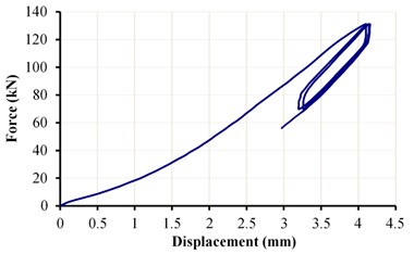
Fig. 8The force-displacement diagram of the LRB sample under a vertical load of 50±15 kN
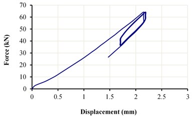
Fig. 9The force-displacement diagram of the LRB sample under a vertical load of 100±30 kN
4.2. Discussion on the results
Table 2 shows that the vertical stiffness of the sample LRB is almost constant for two levels of loading. On the contrary, for the ESI sample with the smaller 5 mm gap the vertical stiffness increases with the load. Moreover, it can be as much as 40 % larger than the LRB sample. When the gap increases from 5 to 8 mm; the vertical stiffness decreases, and gets close to the stiffness of LRB.
Table 2Summary of the test results under vertical load
Percentage increase between the vertical stiffness of ESI and LRB | (MPa) | (kN/mm) | Max. displacement (mm) | Loading range (kN) | Sample type |
19.9 % | 208 | 69.8 | 2.63 | 50 | ESI, 5 mm gap |
39.3 % | 247.8 | 83 | 3.84 | 100 | ESI, 5 mm gap |
3.8 % | 180 | 60.4 | 2.58 | 50 | ESI, 8 mm gap |
15.8 % | 206 | 69 | 4.15 | 100 | ESI, 8 mm gap |
– | 173.6 | 58.2 | 2.19 | 50 | LRB |
– | 177.9 | 59.6 | 3.72 | 100 | LRB |
To find the reason why the vertical stiffness of ESI varies with load one should note that for installation purposes the steel rings have to be constructed with their internal diameter 1 mm larger than that of the rubber core. This leaves the system with a 1mm gap between the rubber core and the steel rings after installation. The vertical load makes the rubber core bulge. Then the vertical stiffness of ESI increases with load after the rubber core fills the gap, and is constrained by the steel rings against more vertical movement. A larger gap between the loading plate and the steel rings considerably reduces the vertical stiffness as compared to the level of vertical load. The reason is related to the portion of the rubber core that at its top remains uncontained between the steel rings.
Another point is that in construction of the ESI sample, the rubber core is wrapped with a Teflon band to prevent the rubber core from being damaged when it is squeezed laterally to the tips of the steel rings which are already made tapered for the same reason. As a result of the low friction coefficient of Teflon, it prevents the steel rings to transmit an excessive portion of the vertical load after the rubber core is completely engaged with them.
5. Results of the test under concurrent vertical and lateral loads
5.1. Shear modulus and horizontal stiffness
In this part of tests, the samples were put under an invariant vertical load while the lateral load changes cyclically. The vertical-lateral loading test is performed according to ISO 227672-1 section 6.2.2 [14]. Thus, the lateral stiffness and equivalent damping ratio in lateral motion (due to friction between the steel rings) were computed.
In accordance with the standard, the loading rate was set at 1 mm/s. Also, in Sec. 6.2.2.6 it recommends the lateral stiffness () to be calculated using Eq. (6):
where, and are the maximum positive and negative shear forces at the third cycle and and are the corresponding horizontal displacements. With the parameters which were previously defined, the effective shear modulus () is also calculated using Eq. (7):
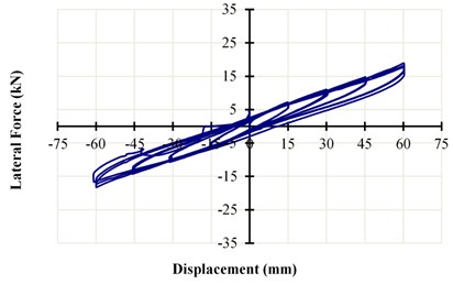
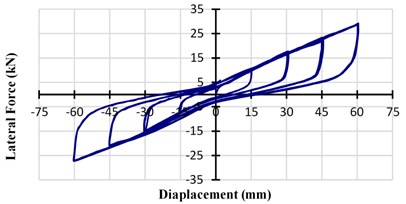
Figs. 10-12 show the horizontal force-displacement diagrams of LRB and ESI having gaps of 5 and 8 mm. The vertical load was kept at 50 kN. In the successive cycles of lateral loading, the maximum shear strain was increased from 25 to 50, 75, and 100 % (equal to 15, 30, 45, and 60 mm displacement, respectively). A quick look at the figures shows that the enveloped area is much larger for both ESI tests as compared to LRB. This fact is illustrated by calculating the equivalent viscous damping in the next section.
As demonstrated in Fig. 10, shear stiffness slightly decreased in all shear strains from the first to the second cycle (i.e., almost 4 %). Moreover, where the shear strains were less than 100 %, the second and the third cycles approximately coincided. However, the strength was degraded when it reached the shear strain of 100 %. In other words, initial stress-strain curves are unique during the first deformation and not repeated, and hence softening occurs. This mechanism reflects the Mullins effect [15]. One of the main factors causing this phenomenon is that in the initial loading, part of the energy is spent on the disentangling polymer chains, and in the next cycle, the chains move among themselves more freely [16]. In the ESI system, this effect is not evident under shear strains (Figs. 11-12), which is due to the frictional behavior of the rings under lateral displacement. This causes the rings to rub on each other and thereby increases the friction coefficient and stiffness. Moreover, in the proposed system, the surface of the hysteresis loops is larger than the hysteresis loops in the LRB system; this indicates the higher energy absorbing capacity of the proposed system. As shown in these figures, the proposed system has a stable hysteretic behavior with small pinching.
Fig. 10The horizontal force-displacement curve of LRB
A comparison between Fig. 11 and 12 shows that the gap reduction causes an increase in the area of the hysteresis loops and thus increases the energy absorbing capacity of the proposed system. This increase is due to the frictional behavior of the rings under lateral displacement. On the other hand, the stiffness and strength values have increased with increasing the number of cycles in each shear strain. In the proposed system, this is more evident with a gap of 5 mm, which can be attributed to a slight increase in the friction coefficient due to the abrasion of steel rings on each other. It must be noted that in the proposed system with a gap of 5 mm, the average increase in stiffness and strength is 2.5 % and 2 % for each cycle, respectively. In the case of a system with a gap of 8 mm, the variations of stiffness are negligible so that the average variation of stiffness in each shear strain would be less than 1 %.
Fig. 11The horizontal-force displacement curve of ESI with a 5 mm gap
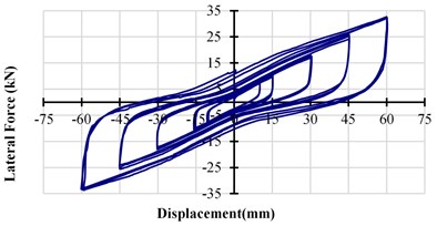
Fig. 12The horizontal-force displacement curve of ESI with an 8 mm gap
In Fig. 13, the shear modulus is displayed at increasing levels of the maximum shear strain. The figure reveals that the shear modulus decreases with increasing shear strains. There are two resembling diminishing trends related to ESI with 5 and 8 mm gap which accompany another one as LRB. Such aspects of behavior will be discussed in the numerical analysis part of this research in a subsequent paper. Another observation is the shear modulus of the ESI sample where the larger gap decreases and becomes closer to the LRB sample. Moreover, the figure demonstrates that the horizontal stiffness of the ESI samples appear to be larger than LRB. Besides, it is 65 % larger than LRB in the maximum situation, at a shear strain of 100 % for an 8 mm gap.
Fig. 13Variation of: a) shear modulus, b) horizontal stiffness in ESI and LRB versus shear strain
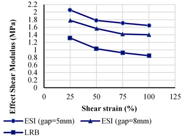
a)
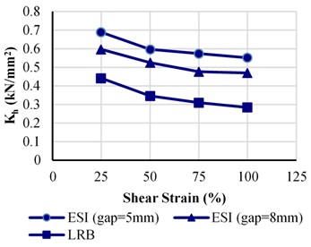
b)
In this system, the friction coefficient of steel rings is measured as 0.35 which relates to the rings material, the polishing rate, and the quality of the rings’ surface. Obviously, the lateral stiffness and damping ratio is corresponding to the friction of sliding rings. As a result, boosting the lateral stiffness leads to augmenting energy absorption and diminishing the lateral deformation of the bearing in the earthquake excitations.
5.2. Equivalent viscous damping ratio
According to Sec. 6.2.2.6 of ISO 227672-1, the equivalent viscous damping ratio is calculated by Eq. (8):
In which is the area enclosed by the hysteresis loops. Fig. 14 shows the variation of the equivalent damping ratio with shear strain under a vertical load of 50 kN. The damping ratio has been calculated for the third loop. The LRB sample shows a damping ratio varying from about 11 % to 8 % for maximum shear strains of 25-75 %. It then rises to 9 % at a 100 % shear strain. On the other hand, the damping ratio of the ESI sample with a 5 mm gap changes between 18-23 % for shear strains of 25-100 %, but unevenly. When an 8 mm gap is used in ESI, its damping ratio becomes almost invariant and changes only between 14-15 %. Altogether, the averages of equivalent damping ratio of the ESI systems are at least 67 % larger than LRB (See Table 3). The damping ratio being larger in ESI is expected because it enjoys an augmented source of energy dissipation due to sliding between several steel rings.
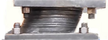
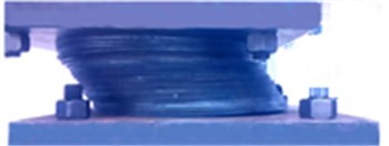
In the system with a 5 mm gap, in lateral displacement the steel rings are engaged with the loading plate that in turn results in larger sliding contact and a larger damping ratio. On the other hand, the sample with an 8 mm gap both is stable in its damping behavior and is showing still a much larger damping ratio with regard to LRB. Fig. 15 represents a close-up snapshot of the ESI system with the two gap widths at large horizontal displacements. It indicates how differently the steel rings are engaged at large displacements.
Fig. 14Comparison of the equivalent damping ratio of the tested system at the third cycle of loading
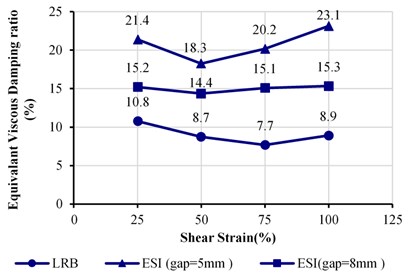
Table 3Equivalent viscous damping of ESI compared with LRB
Percentage increase between the average of ESI and LRB | Average | Sample type |
130 % | 20.75 | ESI, 5 mm gap |
67 % | 15 | ESI, 8 mm gap |
– | 9 | LRB |
Fig. 15Picture of the ESI at a shear strain of 100 %. The sample with a: a) 5 mm gap, b) 8 mm gap
a)
b)
5.3. An economic and technical comparison between the ESI and LRB systems
The proposed system has the following advantages compared to the LRB system:
1) In the LRB system, attachments of the pieces of isolator require welding between multiple steel and rubber layers. For example, to construct the LRB sample in the present study (see Fig. 2), 16 steel plates were welded to 15 rubber layers; this requires a great deal of accuracy in adjusting the thickness of the rubber layers when assembled by expensive vulcanization bonding process. In the proposed system, however, the need for the mentioned welding is eliminated; only the rubber core is welded to the upper steel core and the lower steel loading plate. Hence, the expenses are reduced and the construction process becomes easier.
2) The volume of the rubber used in the ESI system is equivalent to the one used in the LRB system. Therefore, with the removal of steel plates in the proposed system, the height of the isolation system is reduced compared to the LRB system.
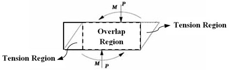
3) Isolation systems are subjected to the bending moment and vertical load due to large shear strain. Fig. 16 indicates that in the LRB, the compression load is tolerated by the overlap region between the upper and lower loading plates, and the bending moment resulting from the P-delta effect is tolerated by tension stresses in the outside part of the region [3]. In the proposed system, with the increase in the section area of the system, steel rings improve the bearing capacity of the system. On the other hand, at the time of increasing shear displacements, the system relied on steel rings and thereby compensated for the reduced section area of the rubber.
4) After the earthquake, all components of the proposed system are controllable and interchangeable.
5) The presence of steel rings will produce a suitable energy absorbing mechanism so that the system will not require extra dampers.
6) The vertical stiffness of the proposed system is more than the LRB system. Therefore, the vertical stresses play fewer roles in the system design.
Fig. 16Overlap regions produced by the shear displacement
6. Conclusions
In this paper, a new base isolation device has been presented. The new device, called ESI for Elastomeric-Sliding Isolator, consists of a cylindrical rubber core and a number of steel rings surrounding the rubber core. The rubber core fills the interior space of the steel rings. The vertical load of the overhead column is applied directly to the rubber core. As regards the incompressibility of the rubber, the vertical stiffness of ESI is more than a conventional Laminated Rubber Bearing, because after loading it widens and bears through a hydro-static pressure on the steel rings. Tendency of the rubber core to bulge under the vertical load and its leaning on the steel rings, makes them to accept part of the vertical load and produce a certain level of frictional force against sliding. This is the main source of energy dissipation in the lateral motion for the proposed system.
A series of vertical and horizontal loading tests were conducted on a sample of the developed isolation device and an LRB device for comparison. Through the tests, the vertical and horizontal stiffness’s of the ESI, the effective modulus of elasticity, the shear modulus, and the equivalent damping ratio of the system were calculated. Although the horizontal stiffness of ESI is higher than LRB, increasing the lateral stiffness in ESI system leads to the augmentation of energy absorption and the diminishing of the lateral deformation of the bearing in the lateral motions. Hence, this study has indicated that the average of equivalent damping ratio of the ESI system is at least 67 % larger than LRB. The ESI sample with an 8 mm gap (13 % of its height) at the top between the loading plate and the steel rings was superior in performance to the one with smaller (5 mm) gap.
The comparison between the LRB system and ESI system shows that in the ESI system, there is no need for welding between the multiple steel and rubber layers, and only the upper and lower parts of the rubber core are welded to the steel loading plates, which leads to cost-saving and ease of construction. Besides, the placement of steel rings around the rubber increases the overall section area of the system, which increases the stability of the system under lateral displacements. Also, after severe earthquakes, all components of the proposed system can be controlled and only the damaged parts will be replaced rather than the whole system. On the other hand, the presence of steel rings, in addition to a significant increase in the vertical stiffness of the system, generates a suitable energy absorbing mechanism so that the system does not need extra dampers.
The second part of this research consists of an extensive parametric numerical study on the parameters affecting behavior of ESI. Results of that study will be presented in a separate paper.
References
-
Naeim F., Kelly J. M. Design of Seismic Isolated Structures: From Theory to Practice. John Wiley and Sons, New York, 1999.
-
Shakib H., Fuladgar A. Effect of vertical component of earthquake on the response of pure-friction base-isolated asymmetric buildings. Engineering Structures, Vol. 25, Issue 14, 2003, p. 1841-1850.
-
Kelly J. M., Konstantinidis D. Mechanics of Rubber Bearings for Seismic and Vibration Isolation. John Wiley and Sons, 2011.
-
Kelly J. M. Earthquake-Resistant Design with Rubber. Second Edition, Springer-Verlag, London, 1997.
-
Ryan K. L., Kelly J. M., Chopra A. K. Nonlinear model for lead-rubber bearings including axial-load effects. Journal of Engineering Mechanics, Vol. 131, Issue 2, 2005, p. 1270-1278.
-
Kumar M., Whittaker A. S., Constantinou M. C. An advanced numerical model of elastomeric seismic isolation bearings. Earthquake Engineering and Structural Dynamics, Vol. 43, Issue 13, 2014, p. 1955-1974.
-
Zayas V. A., Low S. S., Mahin S. A. A simple pendulum technique for achieving seismic isolation. Earthquake Spectra, Vol. 6, Issue 2, 1990, p. 317-333.
-
Gueraud R., Noel Leroux J.-P., Livolant M., Michalopoulos A. P. Seismic isolation using sliding-elastomer bearing pads. Nuclear Engineering and Design, Vol. 84, Issue 3, 1985, p. 363-377.
-
Park K. S., Jung H. J., Lee I. W. A comparative study on aseismic performances of base isolation systems for multi-span continuous bridge. Engineering Structures, Vol. 24, Issue 8, 2002, p. 1001-1013.
-
Mostaghel N., Khodaverdian M. Dynamics of resilient-friction base isolator (R-FBI). Earthquake Engineering and Structural Dynamics, Vol. 15, Issue 3, 1987, p. 379-390.
-
Su L., Ahmadi G., Tadjbakhsh I. G. Comparative study of base isolation systems. Journal of Engineering Mechanics, Vol. 115, Issue 9, 1989, p. 1976-1992.
-
Casciati F., Faravelli L., Hamdaoui K. Performance of a base isolator with shape memory alloy bars. Earthquake Engineering and Engineering Vibration, Vol. 6, Issue 4, 2007, p. 401-408.
-
Ismail M., Rodellar J., Ikhouane F. An innovative isolation device for aseismic design. Engineering Structures, Vol. 32, Issue 4, 2010, p. 1168-1183.
-
Elastomeric seismic-protection isolators – Part 1: Test methods ISO 22762-1. Second Edition, International Standard, Switzerland, 2010.
-
Mullins L. Softening of rubber by deformation. Rubber Chemistry and Technology, Vol. 42, Issue 1, 1969, p. 339-362.
-
Ma C., Ji T., Robertson C. G., Rajeshbabu R., Zhu J., Dong Y. Molecular insight into the Mullins effect: irreversible disentanglement of polymer chains revealed by molecular dynamics simulations. Physical Chemistry Chemical Physics, Vol. 19, Issue 29, 2017, p. 19468-19477.
Cited by
About this article

The generous contribution of Mobtakeran Sadra Sanat Company in producing the testing samples at no cost is gratefully appreciated. Besides, sincere thanks go to the Islamic Azad University, Taft Branch for the kind help by giving access to the laboratory facilities.
