Abstract
Constructions based on long fiber composite frames gaining significant and irreplaceable position through almost all traffic sectors. The aim of this presented work is a study of composite rods made by two ways from pre impregnated fibres. In technical practice, one can find applications of so called “prepregs”, especially for so-called wrapping, which is a gradual helical layering of wide tapes. This is a quite simply method with a good quality of final parts, but the using is limited only for straight shapes. Therefore, a method called winding, which is a simultaneous deposition of larger number of fiber filaments was used to handle the problem for curved shapes and fluently changed cross-sections. Even though this method could expand the using of presaturated fibres, in a real case compared with wrapped parts there is evident imperfect alignment and mutually storing of placed fibers. This could be mainly caused by a significant tortuosity and stickiness of the individual fiber strands. The objective the carried work was to experimentally compare the vibrational - modal behavior of two almost identical rods. One was winded and the second kind was wrapped with the same structure of layers, weight and curing parameters. The results of the two compared tubes, that should be theoretically identical, were significantly different. Another step was compilation of a numerical model and verify its suitability for parts created with the two mentioned production methods. The numerical model was in a good agreement with the empirical obtained from the experiment with wrapped parts. However, the using of this standard model also for winded tube is questionable, because of the significantly differences in founded natural frequencies.
1. Introduction
In recent years using of composite materials is still exponentially growing, thanks to the excellent specific strength, possibilities of customize the properties and achievable weight savings. The use of modern advanced composite materials has gained wide acceptance in the last few decades. Compared to metallic structures, composite laminates offer some unique engineering properties while presenting interesting but challenging problems for analysts and designers [1].
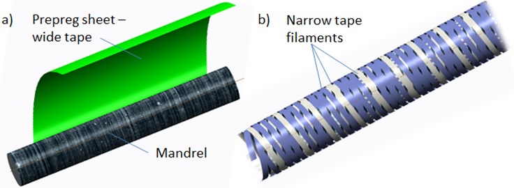
Methods based on epicyclic winding or helical wrapping are generally used for manufacturing of thin-walled composite parts with circular or oval profiles. Those methods are usually used for so-called "wet" form, when bundle of dry placed fibers are impregnated with resin subsequently. Another way is to use of pre-impregnated materials, i.e. prepregs (Fig. 1). Because of their significantly different behavior (sticky, such as double-sided tape), their use is generally limited primarily to manufacturing straight bars. Straight tubes can be produced by so-called wrapping, which is a helical deposition of UD prepreg material in the form of relatively wide tape in several steps and at different angles. However, in technical practice only the straight bars are insufficient. It is necessary to create parts shaped, dissected and 3-D curved. For this purpose, so-called winding technology in unconventional combination with prepreg materials is used (Fig. 2). This is a process when instead of one wide tape, are around the core placed thin tapes from several coils simultaneously. An advantage of this method is the possibility of its application also for curved shapes. With optimal settings, the resulting layer should have the same angle of the fibers, the thickness, the weight and theoretically almost identical mechanical properties (Table 1). During the production of the sample, attention was paid to the aims that composition, number of layers, weight and curing parameters mutually correspond as much as possible.
Fig. 1The way how the fiber material is layered: a) wrapping, b) winding
As the basic, the simplest and simultaneously the most complex way that takes into account the entire spectrum of sub-mechanic parameters for mutual comparison seems to be the vibration test, namely modal analysis. The value of natural frequencies and founded damping characteristics could show us the interrelationship of the basic mechanical parameters of the two compared methods. The stiffness of anisotropic composite plates depends on several factors, i.e. laminate stacking, fiber orientation, surface waviness, number of inner defects (bert) and molding temperature. Polymer matrix composites are known to exhibit viscoelastic behavior, which cause energy dissipation and frequency dependence of both stiffness and damping [2, 3]. The problem of dissipating energy in structures such as to reduce the amplitudes of the vibrations is an important feature in mechanical design. Generally, the damping in metal structures is low, which results in high amplitudes of the vibrations. For fibre reinforced composite materials, damping is higher and it depends on the constitution of the materials [4]. The free vibration of a cantilevered hollow cylindrical solid is investigated based on a general three-dimensional theory of linear elasticity. Usually the classical Euler-Bernoulli beam dynamics theory could be used to analyze this problem. However, more refined theories, often termed “Timoshenko” beam theory, lead to slightly different results, especially at higher frequencies [5, 6]. The process depends on the ratio between diameters (dimensions of the actual cross section) and length. In the fundamental vibration mode of these cylinders may be dominated either the longitudinal extension, transverse bending or axial torsional motions. Bena [7] studied methodology for finding material damping properties at higher frequency and at relatively lower amplitudes.
Table 1Specification of the created rods
Layout [deg] | Weight [g] | Thickness [mm] | Nr. of tapes in 1 ply | Tape width [mm] | |
Wrapped | 55/-55/55/-55 | 163 | 0,8 | 1 | 50 |
Winded | 55/-55/55/-55 | 156 | 0,84 | 10 | 4 |
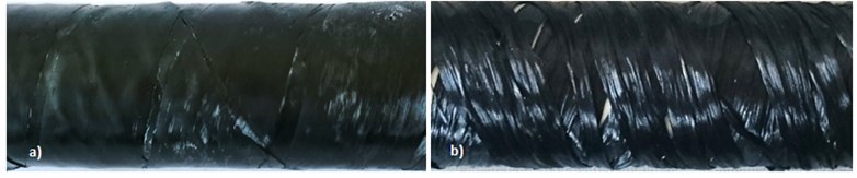
Fig. 2The surface of the a) wrapped b) winded, parts from carbon prepreg
Experimental and analytical characterization of damping is not easy, even with conventional structural materials, and the anisotropic nature of composite materials makes it even more difficult. The techniques for damping measurement often deal with natural frequency or resonant frequency of a system. In general, all apparatus for the investigation of vibration can be categorized as free vibration and forced vibration. Free vibration is a system with the absence of any external input except the initial condition inputs of displacement and velocity [8]. For a forced vibration, a periodic exciting force is applied to the mass. Typical forced vibration techniques include the free-free beam technique and the piezoelectric ultrasonic composite oscillator technique [9].
2. Experiment
The damping in composites involves a variety of energy dissipation mechanisms that depend on vibrational parameters such as frequency and amplitude and these are studied with nondestructive evaluation [7]. For a cantilever beam subjected to free vibration, and the system is considered as continuous system in which the beam mass is considered as distributed along with the stiffness of the shaft, the equation of motion can be written as Eq. (1) [10]:
where, is the modulus of rigidity of beam material, is the moment of inertia of the beam cross-section, is displacement in direction at distance from fixed end, is the circular natural frequency, is the mass per unit length, , is the material density, is the distance measured from the fixed end.
For our case of cantilever beam are the integral constant based on known boundary conditions at the free and clamped point of tube Eqs. (2, 3):
Fig. 3The conducted experiment: a) scheme, b) data processing in Dewetron software interface
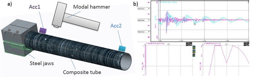
The tested composite tube was mounted with using the segmented prismatic clamping jaws (Fig. 3). The excitation impulse has been done by a modal hammer. Accelerometer Acc1 was using wax stuck near the jaws and at the free end of the tube was stuck the second accelerometer Acc2. Properties of the used accelerometers are, the mass = 1,2 g, maximal sampling frequency 5000 Hz and sensitivity up to 400 g. The excitation force and its response converted to the frequency spectrum and calculated ratio of these two functions is called the transfer function [3]. In this function does not depend on the type of excitation. It is possible to excite randomly, harmoniously or by an impulse. The results of one type of excitation may be used for predicting response of the structure at a different type [11, 12]. According to [13, 14] the excitation and the response signals are digitalized and processed by an analyzer of signals. Based to the analyzed dynamic response, these methods can be subdivided into modal analysis, frequency domain, time domain and impedance domain.
3. Numerical model
Finite-element method (FEM) is a powerful tool without it is today not possible to efficiently design composite parts. Numerical analysis allows us to derive the different strain energies stored in the material directions of the constituents of composite materials [10]. The prediction of the mechanical behavior is very complex problem, because the process includes fiber orientation, stacking sequence, damage mechanisms, interface of plies etc. In our case, the model of shell composite plate of the specified tube (Table 1) has been carried out in Ansys ACP preprocessor (Fig. 4). There is a lot of publication describing modeling of layered materials [3, 4, 7, 14]. For our case it is possible to find inspiration in Crawly & Adams [2] who tried to compare mesh 6×6 with 5×5 and obtained results that variation in natural frequencies is less than 2 %, it means that material properties and boundary conditions are generally not only for composite simulation more important than a very fine mesh.
Fig. 4The created 4plies layout and resultant deformed shape at the 4th mode
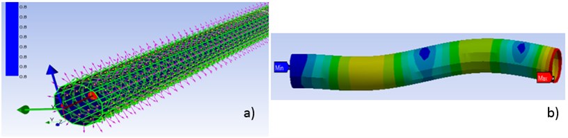
In our case the problem of numerical simulation of composite materials is an assumption of a homogeneous system with perfectly aligned fibers and their uniform distribution throughout the cross section. This idea is commonly applied to the simulation of laminated and wrapped parts. However, how much the results differ for the winding, (i.e. method with large randomness in the fiber alignment and even overlapping of filaments) is a question for comparing individual results in next chapter.
4. Results and discussion
The experimental results for the wrapped parts and numerical model are in a good agreement as could be seen in the Table 2. and in Fig. 5. The determining of resonant zones based on the numerical model of layered shell plate is possible. When assessing the second test case, winded parts, i.e. not the one wide tape but 10 segments of relatively narrow filaments are the found values significantly different. So, we could say that the model results for winded parts are rather informal. It is obvious that in terms of numerical simulation the model must be modified. In the first step is possible to try change the definition of input materials. It means do not use the verified material model [3] of the ideal UD tape but homogenize the new tape by charging the all occurring defects, pores and overlapping.
Table 2The results of experiment and simulation
Mode | I | II | III | IV | V |
Model [Hz] | 146 | 903 | 2293 | 2472 | 3100 |
Exp. Wrapp [Hz] | 130 | 927 | 2240 | – | – |
Exp. Wind [Hz] | 80 | 1280 | – | – | – |
Mode type [Hz] | Bending | Bending | Longintudinal | Bending | Torsion |
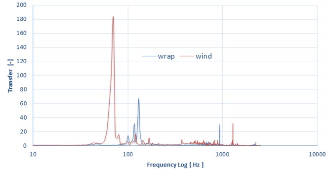
Fig. 5The graph with founded results of experiment winded and wrapped part
5. Conclusions
This work dealt with the experimental and numerical study of modal characteristics (that generally consist all the fundamental mechanical parameters) of thin-walled composite rods. Two sets of samples, one made by winding and second by wrapping of UD prepreg carbon material, were tested. Method one wrapping of a wide tape has a very good surface quality and homogeneity of material characteristics. When assessing agreement of the model and the experiment we obtain quite favorable results. The real problem of this method is that it is suitable only for manufacturing straight and conical round bars, it means that for the current technical requirements to part complexity is insufficient. Therefore, we tried to use non-conventional method – winding combined with pre-saturated materials. This method utilizes instead of one wide tape the segmentation, when each layer consists of 10 narrow strips. This method is suitable for straight shapes and with appropriate setting of the winding angle and can also create curved or closed shapes. A disadvantage is that the fibers are often not ideally aligned as in the case of one wide tape and there are many places of their mutual overlapping which cause the resulting structure forming characteristic warp defects. This all is reflected and causing that the results of ideal model, verified in the experiment with wrapped parts, are from this method considerably different. The primary task for future work would be to assess whether the situation could be compensated only by changing the material model. The second, considerably more complicated, option would be use of a CAD model created of the individual helical strips (Fig. 1(a)) and the empty places around fill with resin. Last idea is in this way created geometry disrupt the relation of the helical sweeps with a pseudo random noise, which should properly represent the real case of arising defects. Subsequently, try to solve the entire model as a composite solid with all the fibers, resin and defects, instead of the idealized shell.
References
-
Kherredine L., Gouasmi S., Laissaoui R., Zeghib N. E. Evaluation and measurement of the damping properties of laminated CFRP composite plates. IOP Conference Series: Materials Science and Engineering, Vol. 28, 2012, p. 012021.
-
Cawley P., Adams R. D. J. A vibration technique for non-destructively assessing the integrity of structures. Composite Materials, Vol. 12, 1978, p. 336-347.
-
Kulhavý P., Petřík J., Srb P., Lepšík P. Vibration response of composite structures. 54th International Conference on Experimental Stress Analysis, University of West Bohemia, 2016.
-
Berthelot J. M., Assarar M., Sefrani Y., Mahi A. El. Damping analysis of composite materials and structures. Composite Structures, Vol. 85, Issue 3, 2008, p. 189-204.
-
Parks D., Anand L. Mechanics and Materials II. Massachusetts Institute of Technology Department of Mechanical Engineering, 2004.
-
Vozkova P. Multiscale Modeling of Mechanical Properties of Textile Composites. Dissertation Thesis, Technical University of Liberec, Liberec, 2008.
-
Bena B. S., Bena B. A., Adarsh K., Vikram K. A., Ratnamd Ch. Damping measurement in composite materials using combined finite element and frequency response method. International Journal of Engineering Science Invention (IJESI), 2010.
-
Botelho E. C., Pardini L. C., Rezende M. C. Damping behavior of continuous fiber/metal composite materials by the free vibration method. Composites Part B, Vol. 37, 2006, p. 255-264.
-
Guan H., Gibson R. F. Micromechanical models for damping in woven fabric-reinforced polymer matrix composites. Journal of Composite Materials, Vol. 35, Issue 16, 2001, p. 1417-1434.
-
Meirovitch L. Analytical Methods in Vibrations by Leonard Meirovitch. 1967.
-
Zou Y., Tong L., Steven G. P. Vibration based model dependent damage identification and health monitoring for composite structures. Journal of Sound and Vibration, Vol. 230, 2000, p. 357-378.
-
Whitney J. M. Shear correction factors for orthotropic laminates under static load. Journal of Applied Mechanics, Vol. 40, 1973, p. 302-304.
-
Piersol A. G. THarris’ Shock and Vibration Handbook. 6th Edition, Mc-Graw Hill, New York, 2010.
-
Hung K. C., Liew K. M., Lim M. K. Free vibration of cantilevered cylinders: effects of cross-sections and cavities. Acta Mechanica, 1995, p. 113-137.
About this article

This publication was written at the Technical University of Liberec as part of the Project “Innovation of Technical Systems Structures with the Use of Composite Materials” with the support of the Specific University Research Grant, as provided by the Ministry of Education, Youth and Sports of the Czech Republic in the year 2017.
