Abstract
Currently there is an effort to replace conventional construction materials – steel, by new modern materials. Ones of the new modern material we can include fiber composites materials. Basic fiber composite materials are composite with fibers of glass, carbon or linen. These types of composites are used in construction of car by their useful properties. Linen composites are used in interior of car for upholstery. Glass or carbon composites are used in the body part of car as bumper, mudguards, and door sections. Next possibility is used carbon fiber composites in construction of car seat. In the case of material replacement, it is necessary to compare the basic mechanical properties between the conventional material and the new material. Due to the anisotropic properties of fibrous composites, it is necessary to compare mechanical properties by experimental method on shape-like samples with real car seat parts. This article describes comparison mechanical properties of steel and carbon fibers composites on the specimen of the tube with circle and rectangle profile
1. Introduction
The car seat consists of four basic parts – a positioning element – a skid, a foam pad, a cover, a support frame. Each of these parts fulfills some of the required features of the car seat, which combines these features in one unit [1].
The positioning element is intended to attach the car seat to the car body. The second basic function is to place the driver in the correct position in relation to the car body, for the correct view of the vehicle and the reach of the controls.
The basic function of foam filling is to allow the seated person a pleasant sitting in the car seat under any conditions. The foam filler is intended to evenly distribute the weight of the seated person over the entire contact area between the seated person and the car seat in all driving modes [2]. Another function of the foam filler is the damping of vibrations coming from the seated vehicle.
The car seat cover fulfills the visual, aesthetic and complements the vibro-isolation properties of the foam padding.
The supporting frame has the task of carrying the other parts of the seat and the seated person. The support frame must also not injure the seated person in the event of an accident. For these reasons, the construction material used is subject to great demands, especially strength and stability of the structure [3-5].
To compare the material properties of two materials with different mechanical behavior, a general method independent of the type of material is required. In this case, a method of comparing the amount of deformation energy and the amount of deformation was used.
2. Theory of the deformation energy
The concept of deformation energy can be imagined as the amount of energy expended to deform the loaded sample. This principle described L. F. Menabrea a C. A. Castiglian. To this day, the principle is known as Castilian’s theorems – Eq. (1). Deformation causes an external load force. By multiplying loading forces and sample deformation we get the workload. This workload is the same as deformation energy.
At the figure of load-displacement curve – Fig. 1, it is possible see value of deformation energy as area under curve (hatched area). The equation – Eq. (1) is correct for interval with Hook’s law:
where: – deformation energy, – deformation work, – loading forces, – deformation of the specimen under forces.
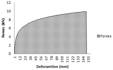
At the figure of load-displacement curve - Fig. 2, that is general depended load on deformation. It is important transformed the Eq. (1) to general formula – Eq. (2):
where: – deformation energy, – deformation work, – stress, – strain.
Fig. 1Graf of load-displacement curve – hook’s law
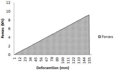
Fig. 2Graf of load-displacement curve – general characteristic
3. Experiment
Load – displacement curve was measured on experimental statement – Fig. 3. Base of the experiment is 3-point bending [6]. A circular cross-section specimen had a diameter 29 mm. Wall thickness 1 mm. A rectangular cross-section specimen had a length of side 30 mm the distance between supports was 380 mm – Fig. 4.
Loading forces was measured by force cell – GTM 2,5 kN. Deformation of the tube was measured by linear potentiometer – HTB 250.
For statistical reasons, it was made 10 measurements from each sample and material.
Fig. 3Experiment – 3 point bending
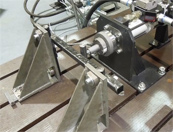
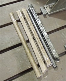
Fig. 4Experiment – specimens – carbon, linen
4. Results
From the experimental measurement, the following results were presented in the form of graphs – Fig. 5. As the graph shows, the smallest value of strain energy should linen specimen – Fig. 5(a). Steel samples followed – Fig. 5(b). The largest absorbed energy had specimens of carbon composites – Fig. 5(c).
Absolut values of absorbed energy are shown in the Table 1.
Table 1Basic size and style requirements
Material | Deformation energy (J) |
Linen | 356 |
Steel | 900 |
Carbon | 382 |
Fig. 5Load-displacement curve – linen composite, steel, carbon composite
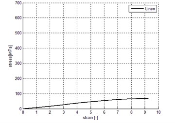
a) Linen
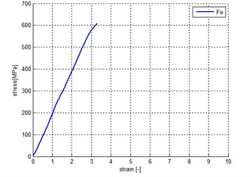
b) Steel
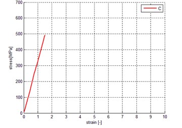
c) Carbon
5. Conclusions
The following conclusions can be drawn from the above results. Carbon composite materials are suitable for the construction of the car seat frame. For used specimen were achieved low overall strength of the carbon fiber composite and thus the low deformation energy. The overall strength of the composite can be increased by a plurality of layers of composite.
References
-
Martonka R. Measuring Properties of Car Seats and Its Innovation. Dissertation Work, Liberec, 2009.
-
Kulhavý P., Petřík J., Srb P., Lepšík P. Vibration response of composite structures. 54th International Conference on Experimental Stress Analysis (EAN 2016), University of West Bohemia, Pilsen, 2016.
-
Petrů M., Bronček J., Lepšík P., Novák O. Experimental and numerical analysis of crack propagation in light composite materials under dynamic fracturing. Communications, Scientific Letters of the University of Zilina, Vol. 16, Issue 3a, 2014, p. 82-89.
-
Srb P., Kulhavý P., Lufinka A., Lepšík P., Fliegel V. Real stress arising in the backrest frame of a car seat. 54th International Conference on Experimental Stress Analysis (EAN 2016), University of West Bohemia, Pilsen, 2016.
-
Syrovátková M., Kulhavý P., Srb P., Petrů M. Testing of tensile properties of carbon prepreg composite rods with adding of a non-composite part. defect and diffusion forum. Defect and Diffusion Forum, Vol. 368, 2016, p. 130-133, https://doi.org/10.4028/www.scientific.net/DDF.368.130.
-
Standards ISO 178 – Determination of Flexural Properties.
About this article

The activities of this Project LO1201 were financed with co-funding from the Ministry of Education, Youth and Sports (Czech Republic) as part of targeted support from the “National Sustainability Program I” Programme.
