Abstract
Adding of a multi-walled carbon nanotubes (MWCNTs) to epoxy resin has shown promising results in improving fracture toughness in bulk epoxy and carbon fiber-reinforced epoxy composites (CFRP). using a hand layup proceeding followed by the so called vacuum bagging process method, carbon fiber-reinforced polymer multi-wall carbon nanotubes (MWCNTs) was added to an epoxy resin with a weight percentage mixing of 1% wt., 1.25% wt., and 1.5 % wt. MWCNTs. Furthermore, the specimen underwent analysis via Fourier-Transform Infrared (FTIR) spectroscopy, and X-ray Diffraction (XRD) spectroscopy, the composites were subjected to a microscopic examination using a Scanning Electron Microscope (SEM). FTIR and XRD verified the folding and unfolding of the polymer, in addition, the mechanical properties including tensile strength, bending stress, and impact behavior were investigated as well as the hardness test. The obtained results showed a significant improvement of about (40 %) in tensile strength, (53 %) in bending stress at 1 % wt. MWCNTs, and (70 %) percentage increment in the strength of Impact at 1.25 % wt. MWCNTs. And the gained hardness was about 40.5 HV which were compared with a reference substance named Carbon Fiber (CF) without any addition of nano materials. Carbon nanotubes have demonstrated their potential to enhance the mechanical properties of fiber-reinforced polymers, so this investigative study employs comprehensive characterization techniques, and demonstrates significant improvements in mechanical properties for the modified polymeric composite materials supported with nano materials.
Highlights
- X-ray diffraction (XRD) analysis reveals distinct reflection peaks in the composite spectra, indicating the presence of MWCNTs within the epoxy matrix.
- Fourier-transform infrared spectroscopy (FTIR) confirms the interaction between the composites, highlighting the successful incorporation of MWCNTs into the epoxy resin.
- Scanning electron microscopy (SEM) analysis of the fractured surfaces demonstrates improved adhesion between the fibers and the epoxy matrix in the hybrid composites with MWCNTs.
- Mechanical testing results reveal that the composite CEWT 1%wt. exhibits significantly higher tensile fracture properties, with a maximum breaking force of 61.9 KN, representing a 40% increase compared to the reference CEWT0%wt. composite.
- The bending force is enhanced in the hybrid composites by adding CEWB 1%, resulting in a maximum bending force of 1311 N, which is 53% higher than that of the reference CEWB %wt. samples.
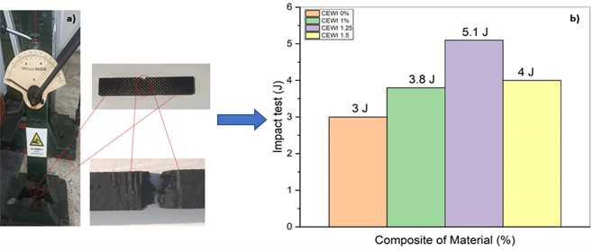
- The highest impact energy absorption capacity recorded is 5.1 J, representing a remarkable improvement of 70%.
1. Introduction
Carbon fiber-reinforced polymer composites (CFRPs) are materials made by combining carbon fibers with a polymeric matrix like epoxy. They offer excellent specific strength and stiffness, making them suitable for various applications due to the high ratio of strength to weight, their ease of manufacturing and lightweight nature makes them ideal for weight-consideration applications [1]. Numerous filler types can be used with resin matrix composite materials, but carbon fiber (CF) is the most significant one for this reason [2]. The multiscale three-phase composite material, combining carbon fiber, carbon nanotubes, and polymer, enhances strength, durability, and damage resistance by mixing CNTs with the matrix [3].
The development of polymer nanocomposites reinforced with carbon nanotubes (CNTs) has been influenced by several variables, such as: the method used to process the nanocomposites, types of CNTs used, their composition content, and their dimensions, the dispersion of CNTs within the matrix, the choice and makeup of the matrix material. The ultimate quality and characteristics of the nanocomposites are influenced by all of these variables combined. When added to composites, CNTs can improve the interface between carbon fiber and the epoxy matrix [4]. This enhanced interface leads to improved load transfer and interfacial bonding, resulting in enhanced mechanical properties. Moreover, the combination of CNTs into composites has been shown to enhance the mechanical characteristics of the proposed composite materials. The addition of CNTs can further increase the strength, stiffness, and toughness of the composite, making it a preferred choice for various applications. FRPs' weak interlaminar shear strength makes them weak to impact loading. Many researches have been done for improving mechanical, thermal, and electrical properties, including adding nanofillers like carbon nanotubes, Nano clays, and graphene nano platelets. This modification of polymeric matrixes has gained significant attention in recently conducted investigative articles [5].
CNT-based nanocomposites use processes such as plastic void formation, CNT rupture, CNT bridging, and CNT pull-out to boost their mechanical properties. CNT pull-out increases toughness and strength, whereas, bridging stops cracks formation from spreading along with the composite structure, and increases toughness, producing better strain-to-failure behavior and an average toughness value of 21.3 %, which suggests stronger resistance to deformation under direct tensile stress [6].
Current research seeks to improve the tensile, flexural, impact, and hardness properties of epoxy composites. Microscopic methods were used to investigate the fracture behavior of composite specimens.
2. Material and method
2.1. Materials
The polymer-based thermosetting epoxy resin EPOLAM 2040 resin is a commercially available liquid resin supplied under the trade name Sika from Sikaaxson Shanghai (China). The plain weave carbon fiber fabric of weight of 92 g/m², supplied by Hangzhou Impact new material Co., Ltd. No 712Qifulu. Zhejiang Province China. the mechanical properties for Tensile strength of CF and Epoxy are (3845,75) MPa respectively. The density for CF and Epoxy are (1.79, 1.1) g/cm respectively. Functionalized MWCNTs were supplied by the company Shenzhen Suiheng Technology Co.itd. the MWCNTs have diameters of (3-15) nm, and a length of 15 µm.
2.2. Manufacturing composite components
2.2.1. MWCNTs combined with epoxy
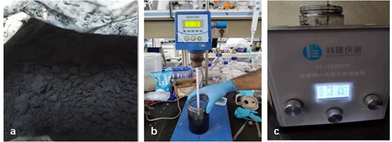
In the experimental procedure described, multi-walled carbon nanotubes (MWCNTs) were manually blended based on a weight mixing method with epoxy base for 5 to 10 minutes using precise amounts of 1%wt., 1.25%wt., and 1.5%wt. of MWCNTs. After the manual blending, ultra-sonication was applied to achieve an even dispersion of the nanotubes within the epoxy. Sonication is a technique that utilizes sound energy to mix small particles in a sample [7]. It helps break down intermolecular interactions and promote uniform dispersion. This sonication process was carried out for 5 minutes. To further ensure good mixing, the HD2010W digital mixer was used at a speed of 1300 rpm for two hours at a temperature of 80 °C. The elevated temperature helped in lowering the viscosity of the produced mixture, making subsequent processing easier. After achieving the desired mixture, the epoxy solution was allowed to cool down to the ambient temperature. Following this, the hardener was added to the solution in a weight-to-volume ratio of 10:3 and manually stirred for 5 to 10 minutes. This step completes the preparation of the epoxy-MWCNT composite Fig. 1. The specific details and parameters mentioned in the experimental procedure demonstrate the meticulous approach taken to ensure proper blending and dispersion of the MWCNTs within the epoxy matrix. These steps are crucial to achieving a homogenous and well-mixed composite material.
Fig. 1Mix epoxy with MWCNTs: a) MWCNTs, b) digital mixer, c) ultra-sonication
2.2.2. Synthesis of carbon fiber/epoxy with MWCNTs
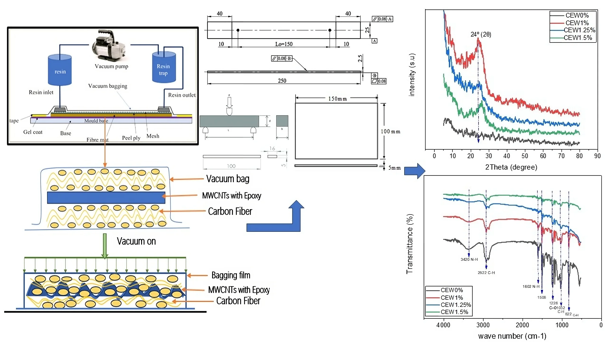
The following provides a detailed description of the production process for the CFRP specimens, the design and layout of the carbon fiber/epoxy/MWCNTs laminated composites can be seen in Fig. 2. Four different material configurations were utilized: Tensile test (CEWT0%wt., CEWT1%wt., CEWT1.25%wt., CEWT1.5%wt.), three-point test (CEWB0%wt., CEWB1%wt., CEWB1.25%wt., CEWB1.5%wt.), Impact test (CEWI0%wt., CEWI1%wt., CEWI1.25%wt., CEWI1.5%wt.), and hardness test (CEWH0%wt., CEWH1%wt., CEWH1.25%wt., CEWH1.5%wt.). These configurations allow for testing and evaluating the mechanical properties and hardness of the composite samples under different conditions and MWCNT concentrations for testing purposes, these configurations represent different compositions of the composite samples, where the percentages denote the amount of MWCNTs used in the composites.
Fig. 2Preparation processes
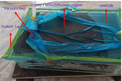
a) Composites by vacuum bag
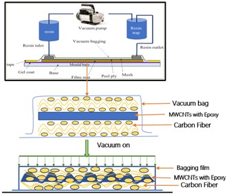
b) Schematic diagram for mixing MWCNTs /Epoxy/ CF
2.3. Characterization of the composite
The Sino Test Equipment CO. was used, following the specifications outlined in ASTM D 3039. Rectangular coupons with specified dimensions of 250 mm × 25 mm and 2.5 mm thickness were cut from the cured composites. A gauge length of 170 mm was used for tensile testing. See Fig. 3(a). Specimens with dimensions of 16 mm width and 5 mm thickness, with a span length of 100 mm (ASTM D 790 standard). Impact tests assess a material’s ability to absorb and dissipate energy under sudden loading conditions [8]. See Fig. 3(b). Izod impact equipment was used to test impact strength that complies with (ASTM 7136) standards, the dimensions of 150×100×5 mm. See Fig. 3(c).
Fig. 3ASTM 3039
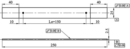
a) The standard specimen according to the ASTM 3039
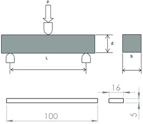
b) The standard specimen according to the ASTM D790
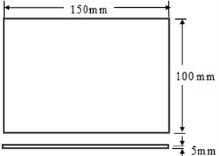
c) The standard specimen according to the ASTM 7136
3. Result and discussion
3.1. Scanning electron microscopy (SEM)
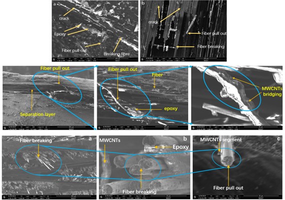
In the upcoming sections, a detailed explanation will be provided regarding the notable enhancement of tensile strength and bending properties exhibited by samples with a weight percentage (%wt.) of CEW1% as well as the impact test with a weight percentage of 1.25%wt. MWCNTs. As a result, it is crucial to carefully select these samples for further examination through deep scanning electron microscopy (SEM) analysis.
In Fig. 4(a), when examining the reference sample CEW0%wt., it is evident that the crack propagation path in the epoxy displays a smooth texture with low surface roughness, indicating a brittle failure. Upon analyzing Fig. 4(b), which represents sample CEWT1%wt., it becomes apparent that the crack propagation on the fracture surface of the MWCNTs-modified epoxy is slightly rougher compared to that of the reference sample. Transition to Fig. 4(c), (d) and (e) the image clearly show the separation of the fiber layers. Bending forces applied to the structure appear to be the cause of this separation. The distribution of Multi-Walled Carbon Nanotubes (MWCNTs), which appear to be encircling the fiber, is another noticeable characteristic.
This can tell us about the fibers' durability and structural integrity in the face of outside stresses at add MWCNTs. Fig. 4(f, g, and h), which shows an impact test sample with the name CEWI1.25%wt. when seen at different magnifications. The inclusion of MWCNTs, which are observed to create around the fiber, is what makes this representation very intriguing.
It is possible to compute the volume fraction of the fiber and matrix. The volume percent of the sample may be calculated by selecting a tiny highlight zone and counting the number of fibers in that small region. The fiber’s cross-sectional area is determined by its dimension. The volume fraction of the matrix () and fiber () is determined by subtracting the total area covered by the fiber from the total area of the sample. It is discovered that the and are, respectively, 0.41 and 0.59. Rule of Volume Fraction and Mixture Calculations [9]:
where: – fiber weights (g); – resin weights (g); – composite weights (g); – volume of the fibers (cm3); – density of composite (gm/cm3); – density of fiber (gm/cm3); – density of resin (gm/cm3); – volume fraction of matrix; – volume fraction of fiber.
Fig. 4SEM images of fracture specimens: a) CEWT0%wt. tensile test reference lower magnification; b) CEWT1%wt. tensile test modify lower magnification; c) CEWB1%wt. bending test modify lower magnification; d) and e) CEWB1%wt. bending test modify high magnification; f), g), and h) CEWI1.25%wt. impact test modify with different magnification
3.2. XRD analysis
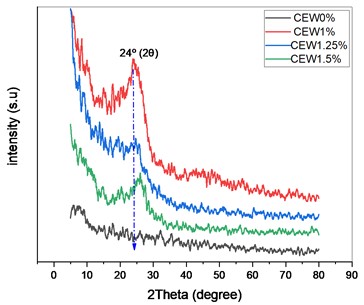
X-ray diffraction (XRD) was utilized to examine the crystalline qualities of the membrane composite. The XRD patterns, depicted in Fig. 7(a), showed reflection peaks that correspond to the diffraction spectra of the composites. The XRD patterns specifically illustrated the CF-reinforced epoxy composites with varying contents of carbon nanotubes (MWCNTs). By analyzing these patterns, it was possible to discern the average bulk structure of the carbon materials. the epoxy/MWCNTs composites show a sharp diffraction peak associated with MWCNTs with almost at 24 which was related to d002. Overall, XRD analysis allowed for the characterization and identification of the crystalline regions present in the membrane composite. By comparing different XRD patterns, the influence of varying CNT contents on the composite structure could be assessed, aiding in understanding the relationship between composition and crystalline properties.
3.3. FTIR analysis
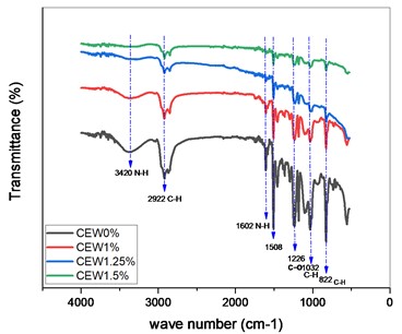
Fourier transform infrared (FTIR) spectroscopy, an indispensable analytical technique, has been employed to meticulously scrutinize the structural composition of Epoxy with Multi-walled carbon nanotubes (MWCNTs) in the current study. The spectral range of the number of waves is confined between (4000 to 500)cm-1, and the corresponding graph is depicted in Fig. 5(b). The absorptions exhibiting broad characteristics, which are observed in the range of (3000 to 3500) cm-1, are primarily attributed to the vibrational modes of hydroxyl (OH) groups present in water molecules and proteins, as reported in previous studies [10]. Moreover, by employing nitrogen as the gas, the peaks that appear at 1602 cm-1 and 1226 cm-1 are attributed to the N-H bending mode and the C-O vibrations of ester carbonyls of fatty acids, respectively [11]. The sharp peak that is observed at an absorbance of 1035 cm-1 is associated with the C-H stretching mode concerning polysaccharides in the cellulose. Furthermore, the FTIR spectra at 3420 cm-1 revealed the assignment of N-H bending, respectively. The band that appears at 2922 cm-1 depicts the asymmetrical C-H stretching for CH3.
Fig. 5a) XRD analysis of carbon fiber / Epoxy with MWCNTs; b) The FTIR spectra of samples carbon fiber with epoxy and MWCNTs
a)
b)
3.4. Analysis of mechanical testing
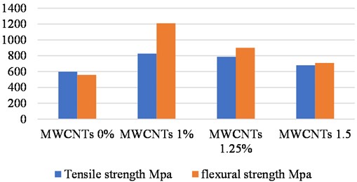
According to the data presented in Fig. 4(a, b) and 5(a), it is evident that the integration of 1%wt. MWCNTs leads to a significant enhancement of the maximum breaking force compared to the reference CEWT0%wt. Specifically, the maximum breaking force and tensile strength are recorded as (61.9 KN, 813 MPa) respectively, the primary reason for this increase in strain to failure upon adding MWCNTs lies in the improved matrix-fiber interfacial connection. It should be noted that carbon fiber has considerably higher rigidity than epoxy in the reference composite.
Analysis of the bending test results reveals that all hybrid composites exhibit higher flexural strength compared to the reference CEW0%wt. The flexural properties follow a similar trend to the tensile values shown in Fig. 6(c, d) and Fig. 7. Among the samples, CEWB1%wt. demonstrates the highest bending force and highest flexural strength are (1311 N, 1210 MPa) respectively, representing a remarkable increase compared to the CEW0%wt. samples specimens. MWCNTs effectively distribute stress because of their aligned and linked structure, which contributes to their exceptional strength and stiffness.
Our findings from both the tensile and bending tests align closely. The inclusion of particles in the matrix introduces surface roughness on the fiber while avoiding damage to the fiber surface. This combination of surface roughness and good interfacial adhesion promotes mechanical interlocking and improved frictional coefficient, ultimately resulting in increased bending strength. Thus, the results of this research confirm and agreement with the literature [12]. which contends that increased carbon nanotube concentrations have a negative impact on tensile strength and bending strength. According to ASTM standards, the tensile strength equation and flexural strength equation are computed [13]:
where: is maximum load in N; is span length = 128 mm; is width of specimen = 13 mm; is thickness of specimen = 4 mm; is the slope of linear portion of load v/s deflection graph.
Fig. 6Test equipment: a) tensile test device; b) tensile force test; c) bending test device; d) bending force test
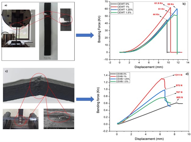
Fig. 7Tensile strength and flexural strength for different ageing conditions
An Izod Impact Test was conducted to measure the impact force of composite specimens. The test was repeated three times, and the average results were used in the data presented in Fig. 8. The experimental findings indicate that composites reinforced with MWCNTs exhibit higher energy absorption capacity. Interestingly, significant differences were observed among the three different composites. However, the composite specimen with the highest impact energy absorption capacity is recorded as 5.1 J, which represents a significant improvement compared to the baseline or reference material it was found that the composite containing 1.25%wt. weight of MWCNTs particles showed the highest impact load, suggesting its superior performance in terms of impact resistance.
Fig. 8Test equipment impact test: a) device impact test; b) impact test for different composites
4. Conclusions
The present study investigates the impact of incorporating multi wall carbon nanotubes (MWCNTs) into an epoxy resin as the matrix material for carbon fiber composites. The following conclusions can be drawn from the study:
1) X-ray diffraction (XRD) analysis reveals distinct reflection peaks in the composite spectra, indicating the presence of MWCNTs within the epoxy matrix.
2) Fourier-transform infrared spectroscopy (FTIR) confirms the interaction between the composites, highlighting the successful incorporation of MWCNTs into the epoxy resin.
3) Scanning electron microscopy (SEM) analysis of the fractured surfaces demonstrates improved adhesion between the fibers and the epoxy matrix in the hybrid composites with MWCNTs.
4) Mechanical tests show that the CEWT 1%wt. composite has higher tensile strength, 40 % more than CEWT0%wt. Additionally, CEWB 1 % exhibits 53 % higher bending force. Impact energy absorption improves by 70 %. The highest hardness, at 40.5 HV, is in the 1%wt. MWCNTs reinforced resin. These enhancements offer potential benefits for composite applications.
References
-
R. F. Gibson, “A review of recent research on mechanics of multifunctional composite materials and structures,” Composite Structures, Vol. 92, No. 12, pp. 2793–2810, Nov. 2010, https://doi.org/10.1016/j.compstruct.2010.05.003
-
H. Fouda, L. Guo, Y. Yue, K. Chen, and K. Elsharkawy, “Synthesis and characterization of hybrid CF/MWCNTS/epoxy resin composite system,” in IOP Conference Series: Materials Science and Engineering, Vol. 220, p. 012021, Jul. 2017, https://doi.org/10.1088/1757-899x/220/1/012021
-
S. U. Khan and J.-K. Kim, “Impact and delamination failure of multiscale carbon nanotube-fiber reinforced polymer composites: a review,” International Journal of Aeronautical and Space Sciences, Vol. 12, No. 2, pp. 115–133, Jun. 2011, https://doi.org/10.5139/ijass.2011.12.2.115
-
O. Khokhar, A. Khajuria, and R. Bedi, “An initial study on the impression creep behaviour of stir-cast GNP reinforced AA6061 composite (AMMC),” IOP Conference Series: Materials Science and Engineering, Vol. 1248, No. 1, p. 012086, Jul. 2022, https://doi.org/10.1088/1757-899x/1248/1/012086
-
J. Zou et al., “Strengthening and toughening effects by strapping carbon nanotube cross-links with polymer molecules,” Composites Science and Technology, Vol. 135, pp. 123–127, Oct. 2016, https://doi.org/10.1016/j.compscitech.2016.09.019
-
H. Aghamohammadi, R. Eslami-Farsani, and A. Tcharkhtchi, “The effect of multi-walled carbon nanotubes on the mechanical behavior of basalt fibers metal laminates: an experimental study,” International Journal of Adhesion and Adhesives, Vol. 98, p. 102538, Apr. 2020, https://doi.org/10.1016/j.ijadhadh.2019.102538
-
M. Hossain et al., “Enhanced mechanical properties of carbon fiber/epoxy composites by incorporating XD-grade carbon nanotube,” Journal of Composite Materials, Vol. 49, No. 18, pp. 2251–2263, Jul. 2014, https://doi.org/10.1177/0021998314545186
-
N. Narkevich et al., “Low-temperature deformation and fracture of Cr-Mn-N stainless steel: tensile and impact bending tests,” Metals, Vol. 13, No. 1, p. 95, Jan. 2023, https://doi.org/10.3390/met13010095
-
A. V. Babaytsev, M. I. Martirosov, L. N. Rabinskiy, and Y. O. Solyaev, “Effect of thin polymer coatings on the mechanical properties of steel plates,” Russian Metallurgy (Metally), Vol. 2017, No. 13, pp. 1170–1175, Mar. 2018, https://doi.org/10.1134/s003602951713002x
-
J. J. Vilatela, R. Khare, and A. H. Windle, “The hierarchical structure and properties of multifunctional carbon nanotube fibre composites,” Carbon, Vol. 50, No. 3, pp. 1227–1234, Mar. 2012, https://doi.org/10.1016/j.carbon.2011.10.040
-
T. S. Gspann, N. Montinaro, A. Pantano, J. A. Elliott, and A. H. Windle, “Mechanical properties of carbon nanotube fibres: St Venant’s principle at the limit and the role of imperfections,” Carbon, Vol. 93, pp. 1021–1033, Nov. 2015, https://doi.org/10.1016/j.carbon.2015.05.065
-
X. Li et al., “Investigation into the toughening mechanism of epoxy reinforced with multi-wall carbon nanotubes,” e-Polymers, Vol. 15, No. 5, pp. 335–343, Sep. 2015, https://doi.org/10.1515/epoly-2015-0143
-
G. M. Odegard and A. Bandyopadhyay, “Physical aging of epoxy polymers and their composites,” Journal of Polymer Science Part B: Polymer Physics, Vol. 49, No. 24, pp. 1695–1716, Dec. 2011, https://doi.org/10.1002/polb.22384
Cited by
About this article

The authors would like to acknowledge the financial supports from the National Natural Science Foundation of China (Grant number: 51705253 and 11572158).
The datasets generated during and/or analyzed during the current study are available from the corresponding author on reasonable request.
The authors declare that they have no conflict of interest.
