Abstract
The response of Fibre metal laminates (FMLs) to low-speed impact, including displacement at impact center, stress, strain response, and metal and fiber damage during the process was studied. Three types of stainless steel based FMLs with carbon fibre reinforced plastic (CFRP) specimens with different interface connections were designed and low-speed impact tests were carried out on these specimens. At the same time, finite element software ABAQUs is also used to simulate the impact process. During this process, we employ a cohesive element to characterize the bonding relationship of the interface, moreover, the influence of interface connection strength on impact resistance performance of FMLS is emphatically studied. The results show that the mechanical response and damage state of FMLS under different interface connection modes are greatly different, and the higher the connection strength, the better the overall impact resistance of the specimen. When the connection strength is poor, the specimen is easy to be separated when subjected to impact, and the metal layer suffers early damage failure, which is not ideal for the whole structure.
Highlights
- Three types of stainless steel based FMLs with carbon fibre reinforced plastic (CFRP) specimens with different interface connections were designed and low-speed impact tests were carried out on these specimens.
- The FEA model of impact of laminated plates is established by using finite element software. In this model, we use a Cohesive element to represent the bonding relationship at the interface, and the simulation results are in good agreement with the experimental results.
- In the impact process of laminates, if the interface debonding occurs, there will be a large gap at the interface in the impact rebound stage, which will seriously affect the strength of the structure.
1. Introduction
Fibre metal laminates (FMLs) are a novel material structure originally developed for aeronautical engineering applications with high fatigue tolerance [1]. Then, more and more people have realized that this structure has the characteristics of light weight and strong impact resistance, and it has been widely used in various fields such as aircraft skin, high-pressure vessel and weapon equipment. Interface debonding, metal plastic deformation and fiber breakage is one of the most important failure mode of FMLS. In recent years, scholars have conducted a large number of studies on the damage evolution process of FMLS, but has not yet formed a mature theory. The mechanical response of the structure and the law of damage evolution are far from enough in the process of laminates being impacted [2]. The processing of interface connection relation of FMLS is the key to study its interface debonding, moreover, TP et al. used Cohesive element to characterize the connection relationship of FMLS during low-speed impact simulation, the results show that this method can simulate the bonding and debonding process of interface [3].
In order to further reveal the mechanical response of FMLS under low-speed impact, FMLS specimens with different interface connection modes were designed in this paper, and low-speed impact tests were conducted on these specimens.
2. Purpose of the experiment
The plastic deformation of the metal layer and the debonding of the interface are the most important failure forms in FMLs. In order to explore the influence of interface bond on the load bearing capacity of laminates under low speed impact, three kinds of specimens with different interface connection modes were designed in this paper, namely mechanical connection, resin adhesion connection and FM300 adhesive bond. By studying the stress-strain response, deformation degree and damage of metal layer and fiber layer when the specimens with three different interface connection modes are subjected to the same load impact (finite element model is required for some indexes), the influence of interface connection strength on the bearing capacity of FMLs has been analyzed.
3. Preparation of the experiment
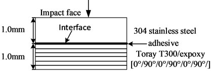
The test specimen in this test is stainless steel based FMLs with carbon fibre reinforced plastic (CFRP) layers, of which the composite material is Toray T300/ epoxy resin with a thickness of 1mm and the metal layer is 304L stainless steel with a thickness of 1mm.
There are three interface connection modes of specimens, namely mechanical connection, resin adhesion connection and FM300 adhesive bond. We numbered these three specimens as JX-1, HY-1 and FM-1 respectively. The structure of the specimen is shown in Fig. 1. JX-1 has no binder, while the binder of HY-1 and FM-1 is resin and FM300 adhesive respectively.
Fig. 1Schematic diagram of specimen structure
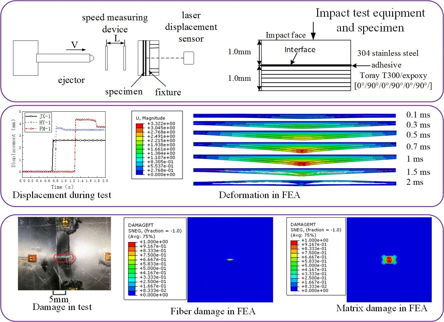
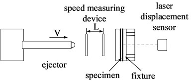
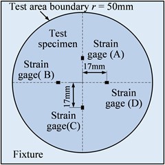
The test equipment in this test is a horizontal impact test platform modified based on high pressure transmitter, as shown in Fig. 2. In this platform, we designed a special fixture to clamp our specimen. The impact bullet is also specially processed, which is made of high-strength bearing steel, and both ends are processed into hemispherical shape. In the process of impact test, strain gauges were used to collect the strain value of the composite layer on the back of the impact center, and the strain collection position was shown in Fig. 2. The laser displacement sensor (Keenses LK-G400) was used to collect the displacement value of the center of the specimen.
The speed measuring device is composed of two pieces of aluminum foil board, both sides of which are connected with voltage data collector respectively. When the bullet passes through the foil, the cardboard is switched on and a voltage square wave signal is generated. Through the time difference between the two square waves and the distance between the two pieces of aluminum foil board, we can figure out the velocity of the bullet by formula .
Fig. 2Schematic diagram of impact test system and the specimen
4. Finite element modelling
The dynamic explicit analysis in finite element software ABAQUS was used to simulate the process of composite laminates subjected to low velocity impact of bullets. In this simulation analysis, the impact process of JX-1 and FM-1 specimens was simulated respectively. Impact bullets are made of high-strength bearing steel, and almost no deformation occurs during the impact process, so they are considered as rigid bodies in simulation. In consideration of the large plastic deformation of the metal sheet during the test impact process, as well as the large metal damage and strain rate hardening and other nonlinear effects, Johnson-Cook plastic model and damage failure model were applied to the metal layer during the simulation process.
The simulated analysis of the strength and damage of composite materials was based on two-dimensional Hashin progressive failure theory, which included fiber tensile fracture, compression buckling, tensile and shear fracture of the matrix, and collapse of the matrix under compression and shear. And the modeling is carried out by using the 8-node quadrilateral plane universal continuous shell element (SC8R).
In the modeling of specimen JX-1, the interface between metal layer and composite layer was set with separable contact connection mode, while for specimen FM-1, the interface was characterized by Cohesive element (COH3D8), and previous studies by TP et al provided us with the parameters of the element [3].
5. Results
According to the velocity measuring device in the previous section, the impact velocity of bullets hitting FMLs is 7.85 m/s, and the impact energy can be calculated as 10.94 J according to the formula 0.5 mv2. After the impact process, the central displacement of the back of the specimen changed as shown in Fig. 5. (data acquisition frequency was 2 kHz), and the finite element simulation results were shown in Fig. 3. and Fig. 4.
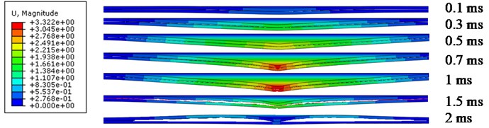
It can be seen from Fig. 3. that during the impact, the integrity of specimen FM-1 between metal plate and composite plate remains good. The laminated plate deformation reaches its maximum at about 1ms, and the displacement value is about 4.97 mm, which is consistent with the displacement value captured by the laser displacement sensor on the back of the impact point during the test. In Fig. 4, the deformation and displacement of the specimen JX-1 were observed, and it was found that the deformation of the FMLs reached its maximum at about 1ms, and the displacement value was about 3.32 mm, which was slightly smaller than that of the specimen FM-1, it was also consistent with the test results. After 1 ms, the FMLs began to rebound, but the degree of rebound of the metal plate was greater than that of the composite plate. At this time, obvious gaps began to appear between the contact surfaces of the specimen JX-1, and at this time, the integrity of the structure was destroyed.
Fig. 3Displacement and deformation of the middle section of specimen FM-1 at different times
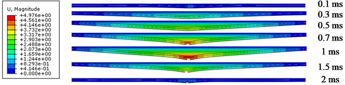
Fig. 4Displacement and deformation of the middle section of specimen JX-1 at different times
The strain variation values of point A (parallel to the direction of the fiber) and Point B (perpendicular to the fiber direction) in the finite element calculation results were compared with the experimental results in Fig. 6 (the curve data were smoothed). By comparing the strain values of the two kinds of specimens, it can be found that the strain of specimen FM-1 is significantly greater than that of specimen JX-1. This is because during the impact process, the interface of specimen JX-1 is separated, the metal plate is greatly deformed, and the bearing capacity of composite layer is weakened.
Fig. 5Variation of impact center displacement with time in the impact process of the three specimens
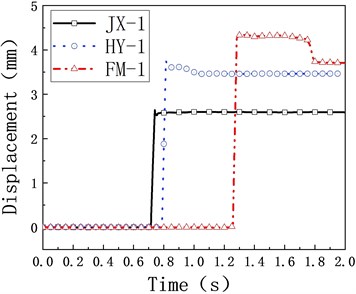
Fig. 6Comparison of strain values between finite element calculation results and test results
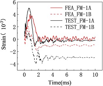
a) Specimen FM-1
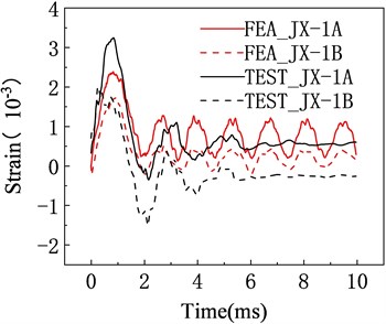
b) Specimen JX-1
The damage of fiber and matrix after impact was observed and compared with the test specimen. In the finite element results, the damage to the fiber and the matrix was determined by the Hashin damage criterion. When the damage index reached 1, the corresponding damage degree reached the maximum, that is, the complete fracture of the fiber or the complete cracking of the matrix.
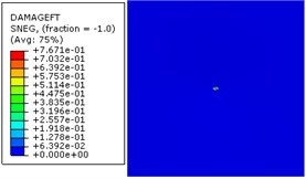
Fig. 7Damage of specimen FM-1
a) Fiber damage in FEA
b) Matrix damage in FEA
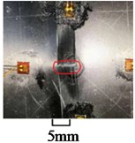
c) Damage in test
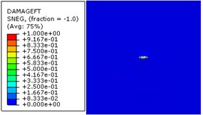
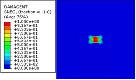
Fig. 8Damage of specimen JX-1
a) Fiber damage in FEA
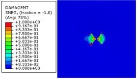
b) Matrix damage in FEA
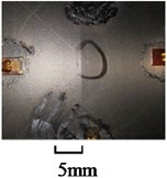
c) Damage in test
It can be seen from Fig. 7 that obvious damage appears on the back of the specimen FM-1. In the center of the specimen is perpendicular to the direction of the fiber, a fiber break mark of about 6 mm in length appears. The shape, position and length of the break mark are consistent between the finite element results and the test results. From the finite element calculation results, it can also be found that the matrix of specimen FM-1 also has a large area of damage at the impact center, and the damage area is similar to the punch impact area.
It can be seen from Fig. 8 that although the specimen JX-1 underwent relatively obvious plastic deformation after impact, no obvious damage occurred. It can be easily found from the FEA results that the maximum damage factor of the fiber is 0.767, so the fiber of specimen JX-1 has not suffered fiber fracture damage. However, obvious damage had occurred to matrix, and the shape of the damage looked similar to peanut, which was hard to find from the test specimen.
6. Conclusions
In this paper, the response of FMLs subjected to low speed impact under different interface connections is analyzed. The horizontal impact tests of three different specimens and the finite element impact process simulation of two specimens were carried out. The results of the experiment and finite element simulation show that the interface debonding has a great influence on the impact response of the FMLs. After debonding, the structural integrity of FMLs will become worse. The metal layer will bear a large load, while the composite layer will bear a small load. For FMLs with poor bond strength, in the stage of impact resilience, a relatively obvious gap will be formed between the metal layer and the composite layer, which will destroy the integrity of the material.
The greater the bonding strength of the laminate interface, the better its integrity. For FMLs with good integrity, the fiber layer will bear greater stress during the impact process, and after the impact process, the fiber layer will have greater deformation and damage, however, the metal layer will have less plastic deformation, it is beneficial to improve the overall durability of the FMLs. The research also shows that the Cohesive element used to represent the interface of FMLs during finite element simulation is consistent with the experimental results, therefore, it is a reliable way during simulation.
References
-
Asundi A., Choi Alta Y. N. Fiber metal laminates: an advanced material for future aircraft. Journal of Materials Processing Technology, Vol. 63, Issues 1-3, 1997, p. 384-394.
-
Morinière F. D. Low-velocity impact on fibre-metal laminates. Ph.D. Thesis, Delft University of Technology, The Netherlands, 2014.
-
Pärnänen T., Kanerva M., Sarlin E. Debonding and impact damage in stainless steel fibre metal laminates prior to metal fracture. Composite Structures, Vol. 119, 2015, p. 777-786.
About this article

The authors would like to acknowledge the financial supports from the National Natural Science Foundation of China (Grant number: 51705253).
