Abstract
Through the combination of theory and experiment, the natural characteristics of the fiber metal laminates thin plates under cantilever boundary are analyzed and verified. Based on the mechanics of composites and classical laminated plate theory, the theoretical model is established. The orthogonal polynomial method and the energy method are used to solve the natural characteristics. Meanwhile the calculation process is proposed. And then, the natural characteristics of a TA2/TC500 fiber metal laminates thin plate are tested. It is found that comparing the calculation results of the frequencies with the test ones, the errors are within the range of 3.4 % to 4.5 %, the trends of modal shapes are consistent as well, thus the effectiveness of above method has been verified.
1. Introduction
Fiber metal laminates (FMLs) are new types of composite materials, which are composed of fiber reinforced layers and metal layers alternately [1-3]. Due to FMLs contained both of the advantages of metal materials, such as good toughness, strong impact resistance, high damage tolerance etc., and composite materials, such as high specific strength and specific stiffness, corrosion resistance and fatigue resistance, they have widely used in the wing, tail and hatch of advanced aircraft [4-6]. Since the above composite materials and the typical structural parts such as beams, plates and shells are often used in harsh environment, it is easy to produce problems such as excessive vibration, fatigue failure and fatigue wear. Therefore, it is necessary to study the vibration characteristics of FMLs thin plates which have important engineering and academic significances in the field of theoretical analysis, dynamic design and fault diagnosis [7].
The natural characteristics, such as natural frequencies and modal shapes, are the basis of in-depth study on the vibration characteristics of structural system. So far, a lot of researches on natural characteristics of FMLs thin plates had been done. Harras [8] et al. established a theoretical model of GLARE 3 fiber metal laminated thin plate under clamped boundary condition and the natural characteristics were obtained. Utilizing the experimental technology, Botelho [9] analyzed the damping characteristics of aluminum plate, carbon fiber/resin composite plate and glass fiber/aluminum alloy FMLs plate. Based on the first-order shear deformation theory, Shooshtari and Razavi [10] deduced the nonlinear ordinary differential equations of the fiber metal laminated thin plate by employing the Galerkin method. Meanwhile, the linear and nonlinear natural characteristics of the structure were analyzed. Payeganeh [11] et al. studied the dynamic characteristics of FMLs plate under low-speed impact, and it was found that parameters such as the lamination sequences, aspect ratios, impact speeds, and mass had significant effect on the dynamic characteristics of FMLs plate. Using Ritz method and ABAQUS finite element method, Ghasemi [12] et al. obtained the dimensionless natural frequency of fiber-reinforced metal laminates under simply supported boundary condition. Then, the influences of geometric parameters and different distributions of metal layers on the vibration parameters were analyzed. Rahimi [13] et al. proposed a three-dimensional elastic analysis theory of FMLs based on the state space differential quadrature method. And the dimensionless frequency of the annular FMLs plate was calculated. Employing Navier method and Hamilton principle, Mahi [14] et al. presented the energy equation of various thin plates by using Ritz method. Then the natural frequencies the corresponding plates under different boundaries were solved. Iriondo [15] et al. studied the damping characteristics of the traditional FMLs plate and the self reinforced polypropylene FMLs plate by utilizing the resonance experiment under forced vibration. Sayyad and Ghugal [16] used the triangle shear method and the theory of normal deformation to establish a dynamic model of multi-layer laminates under simple boundary conditions based on the virtual work principle. Li [17] et al. studied natural frequencies of C-Ti FMLs beams and plates under cantilever boundary condition by employing experiments and ABAQUS finite element method. Meanwhile, the influences of different sizes and different numbers of metal layers on their natural frequencies were analyzed. However, the theoretical derivation had not been done.
It can be found from the available literatures that the researches on the natural characteristics of FMLs thin plate under cantilever boundary were not enough, and most of the literatures had not been verified by experiments. Therefore, it is necessary to conduct further research on its natural characteristics. In this paper, a theoretical model of FMLs under cantilever boundary condition is established based on composite mechanics and classic laminate plate theory. The natural characteristics of the FMLs thin plates are solved by utilizing the orthogonal polynomial method and the energy method. As an example, to demonstrate the feasibility of the proposed model, the experimental test of a TA2/TC500 laminated thin plate is implemented. The calculated and measured results show a good consistency.
2. Theoretical solution of the natural characteristics of the fiber metal laminates thin plates under the cantilever boundary
2.1. Theoretical model
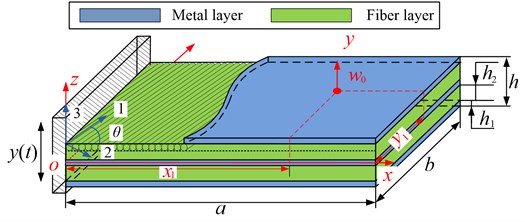
FMLs thin plate is made of metal material and -layer orthotropic fiber and matrix composite fiber reinforced material. Its theoretical model is shown in Fig. 1. In Fig. 1, a rectangular coordinate system is established with the middle plane as the reference plane. The length of the thin plate is and the width is . The sides of the plane are fixed. The thickness of the metal layer is while the thickness of the fiber layer is . Therefore, the total thickness of the thin plate is , the angle between the longitudinal direction of the fiber and the direction is . Its material parameters are expressed as follows, is the elastic modulus of the metal, is the Poisson’s ratio of the metal, and , and are the Young’s modulus of the fiber layer along the fiber direction, vertical fiber direction and in-plane shear in the fiber layer respectively, and are the Poisson’s ratios along the fiber direction and the vertical fiber direction, respectively, and and represent the densities of the metal layer and the fiber layer, respectively.
Fig. 1Theoretical model of the FMLs thin plate under cantilever boundary
Due to the model is a symmetric structure, based on Kirchhoff hypothesis and classical thin plate theory, its displacement components , , along the , , and directions can be expressed as [18]:
where , and represent the displacement of the middle plane of the thin plate respectively, and represents the time.
The strain at any point of the thin plate can be expressed by displacement [18]:
where, , , and , and represent the line strain and shear strain in , and directions respectively.
Therefore, the stress-strain relationship should be represented as [18]:
where, for the metal layer, , , ; for fiber layer, , , , .
In the fiber layer, when the angle between the fiber direction and the -axis is , by using the rotation axis formula, the stress-strain relationship of the -th layer fiberboard is obtained as follows:
where:
where represents the -th layer fiber and represents the angle between the -th layer fiber and the -axis direction.
2.2. Energy equations
In the bending vibration of thin plates, the kinetic energy and strain energy of the metal layer of the model can be expressed as follows:
The kinetic energy and strain energy of the fiber layer can be expressed as follows:
where is the area of the thin plate. Eq. (1) and Eq. (2) are introduced into Eq. (6), then Eq. (3) and Eq. (4) are introduced into Eq. (6a)-(6d) and (6e)-(6f) respectively. The expressions of kinetic energy and strain energy of metal layer and fiber layer can be obtained through the middle displacement :
By adding the kinetic energy and strain energy of each layer, the total kinetic energy and strain energy can be obtained as:
2.3. Solution by orthogonal polynomial method
As the orthogonal polynomial method has clear solution principle, fast calculation speed, and can be applied to solve the natural characteristics of various boundaries, reference [14], using this method, the mid plane displacement is expressed as:
where and are called the truncation coefficients for solution, is a pending parameter, is the angular natural frequency, and are orthogonal characteristic polynomials, and their expression is as follows:
where and are coefficient parameters, and are polynomial functions for determining boundary conditions, and their expression is as follows:
where is the weighting function used in the orthogonalization process, and usually ; , , , represent boundary state parameters at 0, , 0, respectively. When the boundary state is free, the value of the corresponding boundary state parameter is 0; When the boundary state is a simply supported boundary, the value of the corresponding boundary state parameter is 1; When the boundary state is a fixed boundary, the corresponding boundary state parameter is 2. According to the model established in this paper, the boundary state parameters , , , correspond to the boundary state. Therefore, the values of , , , are 2, 0, 0, 0 [14].
By substituting Eq. (9) into Eq. (8), the expressions of maximum kinetic energy and maximum strain energy with undetermined parameters can be obtained by making 1 and 1, respectively:
So the energy equation can be expressed as:
Take the partial derivative of the energy equation with respect to the undetermined coefficients . Then, set it equal to 0, thus:
Solving the generalized eigenvalue problem of the minimum pending parameters of the Eq. (13) can be obtained:
where and are the stiffness matrix and mass matrix of the structural system, respectively, and the feature vector . If Eq. (15) is solved, the determinant of the coefficient matrix of the feature vector is 0, that is:
The natural frequencies of the structure can be obtained by solving Eq. (16), the accuracy of which is determined by the values of and . the larger the values of and , the higher the accuracy of the results. In this study, setting 8 and 8 can satisfy the calculation accuracy [19].
Taking the obtained natural frequencies back into Eq. (15), the undetermined parameters of can be obtained, and taking them into Eq. (9), the modal shapes of each natural frequency can be obtained.
3. Analysis process of natural characteristics of fiber metal laminates thin plate
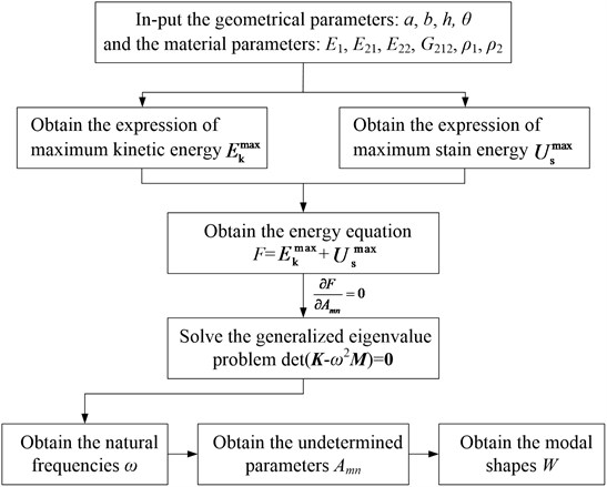
In this section, based on the MATLAB software, the corresponding program is written, and the analysis process of the natural characteristics of the FMLs thin plate under the cantilever boundary condition is proposed. The flowchart is given in Fig. 2, and corresponding specific steps are as follows:
1) Input the geometrical parameters and material parameters of FMLs thin plate.
Firstly, the length, width, thickness of metal layer and fiber layer, fiber angle of each layer and other geometric parameters of FMLs thin plate are given. Then, the elastic modulus of metal and fiber, Poisson’s ratio, material density, metal elastic modulus, elastic modulus and shear modulus of fiber along the fiber direction and perpendicular to the fiber direction are input respectively to prepare for calculation.
2) Obtain the expression of maximum kinetic energy and maximum strain energy.
The displacement component expression Eq. (1) is substituted into the general kinetic energy expression Eq. (8a) and the general strain energy expression Eq. (8b), and the later generations are arranged into the middle plane displacement expression Eq. (14) of the orthogonal polynomial method. According to different boundaries, and are determined. After finishing, set to obtain the maximum kinetic energy , and set 1 to obtain the maximum strain energy .
3) Obtain the natural frequencies.
Take the maximum kinetic energy and maximum strain energy obtained in step 2 into Eq. (13), and get the specific expression of energy equation . By solving the generalized eigenvalue problem of the minimum undetermined parameter, i.e. let 0, the natural frequencies of FMLs can be obtained.
4) Obtain the modal shapes.
Taking the obtained natural frequencies into Eq. (15), the undetermined parameters can be obtained, and the obtained parameters can be taken back to the displacement expression Eq. (9) to obtain the modal shape of each order.
Fig. 2The flowchart of solving the natural characteristics of FMLs plate
4. A case study
Taking a TA2/TC500 FMLs thin plate as the research object, the natural frequencies and modal shapes of the thin plates are tested under cantilever boundary condition. The length, width and height of the object are 200×300×2.65 mm. Among them, the thickness of the metal layer is 0.3 mm, the density is 4.15×10³ kg/m3, the elastic modulus is 108 GPa, and the Poisson’s ratio is 0.3; The total thickness of a fiber layer is 0.875 mm, the elastic model of the fiber along the fiber direction is 136 GPa, the elastic modulus of the vertical fiber direction is 7.92 GPa, the shear modulus is 3.39 GPa, Poisson’s ratio 0.3, density 1780 kg/m3, the laminate configuration is [(0°/90°)s/0°/(90°/0°)s]. 14 layers are laid in total, and each layer has the same thickness and fiber volume fraction. The short side is clamped during installation, and the clamping length is 30 mm.
Fig. 3The natural characteristics experiment system of FMLs thin plates
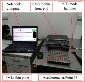
In order to verify the correctness of the calculation method proposed in this paper, a test system is built as shown in Fig. 3. The experiment adopts the method of multi-point excitation and single-point response, which is carried out by a modal hammer. Before the test, the tested plate is equally divided into 9 parts in the length direction and 10 parts in the width direction. The exciting points are numbered from 1 to 110. Furthermore, the response point is set at point 33. Meanwhile, the test bandwidth is set as 1600 Hz, the number of spectrum lines is 4096, and the frequency resolution is 0.39 Hz. In order to improve the test accuracy, a force index window function is also added to the excitation signal, and an exponential window function is added to the response signal.
During the test, PCB086C01 modal hammer is used to excit the FMLs plate three times at each exciting point, and LMS mobile front-end is used to collect the excitation signal and response signal. Finally, the first 7 natural frequencies and modal shapes can be obtained through the storage and analysis of notebook computer equipped with LMS Test. lab 14A analysis software. The obtained natural frequencies and modal shapes are shown in Table 1. For comparison purposes, the frequencies and modal shapes calculated by MATLAB software and corresponding errors are listed in Table 1.
By comparing the calculation results with the experimental ones, it can be found that the errors between the calculation results of the natural frequency of the FMLs thin plate and the experimental results are 3.4 % and 4.5 %, which is within an allowable range. Meanwhile, the corresponding modal shapes are completely consistent. Thus, the correctness of the theoretical analysis method can be verified.
5. Parameters studies
The theoretical model has been verified in section 4. Therefore, in this section, the relationship between the material and geometric parameters of FMLs plate and its frequencies will be discussed. For the convenience of calculation, the thickness of the fiber layer is set to be 0.1 mm, and the laminate configuration is [0°/90°]s.
5.1. The influence of material parameters on the natural frequency of FMLs plate
In this section, in order to compare the relationship between different material parameters and the natural frequencies of the structures studied, the densities and elastic moduli of aluminum, titanium and stainless steel materials are respectively selected for calculation and discussion. The corresponding material parameters are shown in Table 2. The length × width × thickness of the plate is set to be 300 × 200 × 2.9 mm. The thickness of the matal layer is 0.3mm, therefore, the numbers of the fiber in the fiber layers are 10. Meanwhile, the calculated results of the first 7 orders of the natural frequencies of the FMLs plates with different material parameters are shown in Table 3.
Table 1The first 7 natural frequencies and modal shapes of FMLs thin plate by calculation and experiment
Order | Calculation frequency (Hz) | Test frequency (Hz) | Error (%) | Calculation vibration mode | Test vibration mode |
1 | 34.4 | 35.7 | 3.8 | 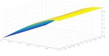 |  |
2 | 71.9 | 75.1 | 4.5 | 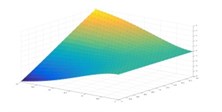 | 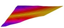 |
3 | 215.6 | 222.7 | 3.3 | 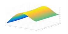 |  |
4 | 296.9 | 309 | 4.1 | 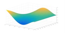 | 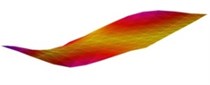 |
5 | 475.0 | 491.2 | 3.4 | 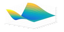 | 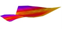 |
6 | 603.3 | 624.1 | 3.4 | 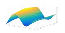 | 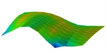 |
7 | 699.6 | 726.9 | 3.9 | 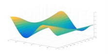 | 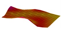 |
Table 2The material parameters of the FMLs plate
Type | Material | Elasticity modulus (GPa) | Density (kg/m3) |
Case 1 | Aluminum | 72 | 2700 |
Case 2 | Titanium | 108 | 4150 |
Case 3 | Stainless steel | 180 | 7800 |
Table 3The calculated frequencies of FMLs plate with different material parameters
Order | Natural frequencies (Hz) | ||
Case 1 | Case 2 | Case 3 | |
1 | 32.2 | 32.5 | 31.8 |
2 | 65.7 | 71.7 | 95.1 |
3 | 195.0 | 202.9 | 198.6 |
4 | 305.9 | 322.3 | 329.7 |
5 | 462.5 | 475.4 | 474.3 |
6 | 565.6 | 572.7 | 572.4 |
7 | 667.3 | 693.9 | 697.0 |
It can be found from the above results that the natural frequency of the structure is the smallest when the material parameters of aluminum are selected. Furthermore, when the material parameters of titanium and stainless steel are chosen, the difference of the natural frequencies of FMLs plate is very small. It may be caused by the combined effect of the modulus of elasticity and the density.
5.2. The influence of geometric parameters on the natural frequency of FMLs plate
In this section, the influence of different geometric structures on the natural frequency of FMLs plate is discussed by setting different metal layer thickness and fiber layer thickness. The elasticity modulus and density are set to be the same as them in Section 4. And the length × width × thickness of the plate is set to be 300 × 200 × 3.0 mm. Besides, the corresponding geometric structure parameters are shown in Table 4. The calculation results of natural frequencies for different geometric parameters are shown in Table 5.
Table 4The geometric construction of the FMLs plate
Type | Thickness of the metal layers (mm) | Thickness of the fiber layers (mm) | Numbers of the fiber layers |
Case 4 | 0 | 3.0 | 1 |
Case 5 | 0.2 | 1.2 | 2 |
Case 6 | 0.4 | 0.9 | 2 |
Table 5The calculated frequencies of FMLs plate with different geometric construction
Order | Natural frequencies (Hz) | ||
Case 4 | Case 5 | Case 6 | |
1 | 35.8 | 34.5 | 32.9 |
2 | 77.4 | 68.8 | 62.5 |
3 | 224.4 | 215.5 | 205.3 |
4 | 338.1 | 320.4 | 308.4 |
5 | 493.0 | 487.7 | 465.7 |
6 | 605.2 | 581.7 | 571.2 |
7 | 717.3 | 701.4 | 688.6 |
It can be seen from the above results that with the increase of the thickness of metal layer, the natural frequencies of FMLs plate decrease gradually. The reason for this phenomenon may be that, when the total thickness is certain, the density of the metal layer is higher than that of the fiber layer. With the increase of the thickness of the metal layer, the thickness of the fiber layers gradually decreases, which leads to the increase of the overall mass and then reduces the natural frequency of the structure.
6. Conclusions
In this paper, the natural characteristics of the FMLs thin plate under cantilever boundary condition are analyzed and verified by combining theory with experiment. By comparing the calculation results with the experimental ones of the TA2/TC500 thin plate, it can be seen that the errors of the natural frequencies between the calculated results and the experimental ones are 3.4 % and 4.5 %, which are within an allowable error range. Besides, the corresponding modal shapes are completely consistent, which further verifies the correctness of the theoretical analysis method. By using the method proposed in this paper, the analysis and prediction of the natural characteristics of FMLs thin plate under the cantilever boundary condition can be realized. Meanwhile, by studying the relationship between the parameters, such as material and the geometric ones, and the natural frequencies in the structure, it can be found that the natural frequency of the structure is the smallest when the material parameters of aluminum are selected. And the natural frequencies of FMLs plate decrease gradually with the increase of the thickness of metal layer. Furthermore, the theoretical model is also applicable to the analysis of the natural characteristics of FMLs laminates thin plates under different boundaries conditions such as free, simply supported and clamped. However, the results of this paper have not analyzed and discussed the natural characteristics of FMLs plates with asymmetric and multi-layers. And the corresponding results need to be further demonstrated.
References
-
Asundi A., Choi A Y N. Fiber metal laminates: An advanced material for future aircraft. Journal of Materials Processing Technology, Vol. 63, Issues 1-3, 1997, p. 384-394.
-
Sinmazçelik T., Avcu E., Bora M. Ö., et al. A review: Fibre metal laminates, background, bonding types and applied test methods. Materials and Design, Vol. 32, Issue 7, 2011, p. 3671-3685.
-
Vlot A., Vogelesang L. B., Vries T. J. D. Towards application of fibre metal laminates in large aircraft. Aircraft Engineering and Aerospace Technology, Vol. 71, Issue 6, 1999, p. 558-570.
-
Marsh G. Airframers exploit composites in battle for supremacy. Reinforced Plastics, Vol. 49, Issue 3, 2005, p. 26-32.
-
Vogelesang L. B., Vlot A. Development of fibre metal laminates for advanced aerospace structures. Journal of Materials Processing Technology, Vol. 103, Issue 1, 2000, p. 1-5.
-
Wang Y. G., Liang X. Z. Fiber-metal laminate technology and large aircraft. Academic Annual Meeting of FRP/Composite Materials, 2010, (in Chinese).
-
Weaver W., Timoshenko W., Young S. P., et al. Vibration Problems in Engineering. Constable and Co. Ltd, 1937.
-
Harras B., Benamar R., White R. G. Experimental and theoretical investigation of the linear and non-linear dynamic behavior of a glare 3 hybrid composite panel. Journal of Sound and Vibration, Vol. 251, Issue 2, 2002, p. 281-315.
-
Botelho E. C., Campos A. N., Barros E. D., et al. Damping behavior of continuous fiber/metal composite materials by the free vibration method. Composites Part B, Vol. 37, Issue 2, 2005, p. 255-263.
-
Shooshtari A., Razavi S. A closed form solution for linear and nonlinear free vibrations of composite and fiber metal laminated rectangular plates. Composite Structures, Vol. 92, Issue 11, 2010, p. 2663-2675.
-
Payeganeh G. H., Ghasemi F. A., Malekzadeh K. Dynamic response of fiber–metal laminates (FMLs) subjected to low-velocity impact. Thin-Walled Structures, Vol. 48, Issue 1, 2010, p. 62-70.
-
Ghasemi F. A., Paknejad R., Fard K. M. Effects of geometrical and material parameters on free vibration analysis of fiber metal laminated plates. Mechanics and Industry, Vol. 14, Issue 4, 2013, p. 229-238.
-
Rahimi G. H., Gazor M. S., Hemmatnezhad M., et al. Free vibration analysis of fiber metal laminate annular plate by state-space based differential quadrature method. Advances in Materials Science and Engineering, Vol. 3, Issue 2014, 2014, p. 653-659.
-
Mahi A., Bedia E. A. A., Tounsi A. A new hyperbolic shear deformation theory for bending and free vibration analysis of isotropic, functionally graded, sandwich and laminated composite plates. Applied Mathematical Modelling, Vol. 39, Issue 9, 2015, p. 2489-2508.
-
Iriondo J., Aretxabaleta L., Aizpuru A. Characterisation of the elastic and damping properties of traditional FML and FML based on a self-reinforced polypropylene. Composite Structures, Vol. 131, 2015, p. 47-54.
-
Sayyad A. S., Ghugal Y. M. On the free vibration analysis of laminated composite and sandwich plates: A review of recent literature with some numerical results. Composite Structures, Vol. 129, 2015, p. 177-201.
-
Li R., Chen X. H., Liu P. Y. Free vibration test and numerical analysis of Ti-C fiber metal laminate. Acta Materiae Compositae Sinica, Vol. 33, Issue 5, 2016, p. 1064-1071.
-
Xing Y. F., Liu B. The Precise Solution of Free Vibration of Plates and Shell. Science Press, 2015.
-
Kou H., Yuan H. Rub-induced non-linear vibrations of a rotating large deflection plate. International Journal of Non-Linear Mechanics, Vol. 58, 2014, p. 283-294.
About this article

This study was supported by the National Natural Science Foundation of China 51505070.
