Abstract
According to the basic principle of statistical energy method, the high frequency SEA model of the full vehicle is established. Through the comparison of simulation and test results, the error of power based noise reduction (PBNR) and interior sound pressure level response is less than three dB, which proves the accuracy of high frequency simulation model. Through the design of different schemes, the sensitivity analysis of parameters such as material parameters, internal loss factor and leakage rate to the model is obtained. The research results show that the accuracy of material parameters, internal loss factor and leakage rate can improve the accuracy of high-frequency simulation model. The sensitivity analysis can provide some ideas for vehicle high frequency noise model adjustment and modification.
1. Introduction
Statistical energy analysis (SEA) is an energy-based analysis method, usually used for higher frequency sound and vibration prediction and used for vehicle NVH (noise, vibration, and harshness) design and development. In this paper, the PBNR [1] and interior noise of the full vehicle are tested, and the SEA model of the full vehicle is established. The accuracy of the model is verified by comparing the test results with the simulation results. On this basis, the influence of material, leakage and loss factor on the accuracy of the model are studied.
2. The basic principle of random analysis
SEA can predict the average noise and vibration levels. SEA model prediction is described by power and energy, and the power balance equation can be used to study the flow of energy in each subsystem [2-4]. The energy flow of a simple two subsystem is shown in Fig. 1.
Fig. 1Energy flow between subsystem
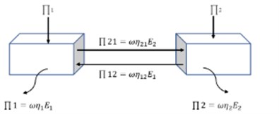
The power balance equations of subsystem 1 and subsystem 2 are as follows:
where: , is the external input power; is the natural frequency of the subsystem; , is the internal loss factor of the subsystem; is the coupling loss factor from subsystem 1 to subsystem 2; is the coupling loss factor from subsystem 2 to subsystem 1; , the energy is subsystem.
For subsystems, the power flow balance equation is as follows:
where: is the natural frequency of the subsystem; is the internal loss factor of the subsystem; is the coupling loss factor from subsystem to subsystem ; is the average sound pressure of cavity subsystem ; is the air density, is the speed of sound; is the volume of cavity subsystem .
2.1. Division of subsystems
Divide the structural subsystem according to the principles of similar modal groups, physical characteristics of the structure and geometric characteristics of the structure. According to its geometric structure, door, column and ground beam are represented by single curvature plate, and the rest are represented by flat plate. Because the analysis conditions are static, there are no accessories such as wipers, rearview mirrors, etc.; because the external sound field in this article is to load the external sound cavity, the wheels, suspension and transmission system are not considered; the structure is small, such as stiffeners, stiffeners, etc. Has little effect on acoustic performance and can be ignored.
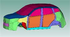
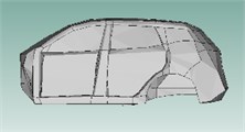
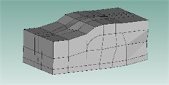
The interior acoustic cavities are established to solve the sound pressure response of different positions in the vehicle under different working conditions, the external acoustic cavities are established to better simulate the excitation of the sound field outside the vehicle body. Since the main research is on the sound pressure level of the right ear of the driver and the right ear of the rear right passenger, the sound cavity in the car is divided into left and right divisions, front row (head, waist and leg), rear (head, waist and leg). In the vehicle, the trunk compartment sound cavity (upper and lower part), the inner sound cavity of the instrument panel, the inner sound cavity of the center console, and the spare tire sound cavity are established. The seat is airtight and airtight. In order to ensure the non-transmission of energy, the seat acoustic cavity is not reserved. The external sound cavity is mainly based on the dividing boundary of the internal sound cavity. The surface of the vehicle is extended 700-1000 mm. The battery pack and the front and rear motors under the floor are sealed and airtight. To ensure that energy is not transmitted, the battery pack and the front and rear motor sound cavities are deleted. The full-vehicle model as shown in Fig. 2.
Fig. 2Vehicle SEA model
2.2. Determination of basic parameters of SAE model
Modal density is a measure of the energy storage capacity of a vibration system. In this paper, the modal density of subsystem is obtained by theoretical calculation and experimental admittance method [5].
The internal loss factor of a complex subsystem is the ratio of the energy lost per unit time to the average stored energy of the subsystem in unit frequency. The steady-state energy flow is obtained by obtaining the input power and system energy of input excitation. The loss factor of the interior acoustic cavity passes through [6].
Coupling loss factor refers to the ratio of energy loss per unit time to average stored energy in unit frequency. It includes structure coupling, structure cavity coupling, and cavity coupling. In the vehicle SEA model, this paper selects the line connection for the structure connection, the acoustic cavity connection and the surface connection for the structure acoustic cavity connection [7].
The calculation formula of surface connection between structures, acoustic cavity and acoustic cavity, structure and acoustic cavity are as follows:
where: is the length of any curve, generally can be get the integral. is the speed of sound, is the partition area, is the volume of the sound field subsystem , is the transfer coefficient. is the cavity density, is the structural density.
2.3. Sound field test and PBNR test of the full vehicle
In the semi-cancellation and rotating hub laboratory, the outside sound field of the sample vehicle is measured at 80 Km/h and 100 Km/h. During the test, the door and the front engine room are closed, and the interior of the car should be kept quiet. The exterior sound field distribution points are the wheels, the outside of the door glass and the outside of the door (front door, rear door, rear door), (front door, rear door, rear door), roof-front left, front right, left middle, right middle, left rear, Rear right, front left, front right, rear left, rear right of the floor, the left and right bottoms of the luggage compartment, the left and right bottoms of the front and rear motors, and the driver's right ear in the car are equipped with BK microphones to collect the sound pressure levels of the measuring points outside and inside the car.
The vehicle PBNR test is carried out in a semi-anechoic room. According to the principle of reciprocity, the high-frequency volume sound source is placed on the driver's right ear and the right ear of the rear right passenger. BK microphones are placed in the engine compartment, the left front wheel, the left rear wheel and the floor. 3 microphones are placed in each sound field area. The LMS noise and vibration test system is used to test the sound pressure of the area outside the car. The measurement results of the 3 microphones Take the average value as the sound pressure of the sound field. In the test, the door and the front engine room are closed, the interior of the car should be kept quiet, and the car should not work:
where: is the amplitude of the transfer function of the measured sound pressure to the volume acceleration.
3. Simulation analysis and experimental verification of vehicle interior noise
The modal density, the internal loss factor, the coupling loss factor and the external sound field excitation are used to obtain the full vehicle SEA simulation model.
3.1. Simulation analysis and test verification of vehicle PBNR
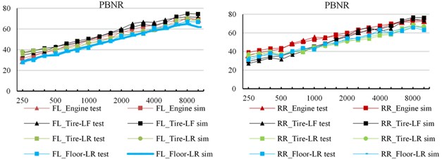
The sound pressure levels of engine compartment, left front wheel, left rear wheel and floor are calculated by applying unit power (1 W, 120 dB) excitation to the acoustic cavity of driver’s right ear and right rear passenger’s head respectively, so as to obtain the results of vehicle simulation PBNR analysis.
Fig. 3The noise PBNR simulation value is compared with the test value
3.2. Simulation analysis and experimental verification of interior noise pressure
Establishing the SEA model of the full vehicle, it is necessary to verify and adjust the model to ensure the accuracy of the model. The sound pressure level in the whole vehicle are the speed is 80 km/h, 100 km/h, the test and simulation benchmarking of the driver's right ear head sound pressure. It can be seen from Fig. 4 that under the working condition at a constant speed of 80 km/h and a constant speed of 100 km/h, the coincidence is good in the frequency band greater than 500 Hz, and the error is basically within 3 dB, and the error under 80 km/h working condition is smaller than that at 100 km/h.
Fig. 4Sound pressure level of vehicle interior noise

4. Sensitivity analysis of full-vehicle SEA model
4.1. Effects of acoustic materials
In order to analyze the response of different materials to the vehicle PBNR and the sound pressure in the vehicle. The influence of laminated glass with the same thickness and different composite materials on PBNR and sound pressure level inside the vehicle is selected. Case 1: Tempered Glass+Solutia Saflex+Tempered Glass. Case 2: Tempered Glass+Tempered Glass Laminate polymer+Tempered Glass. The thickness of both schemes is 2.1 mm+0.76 mm+2.1 mm.
It can be seen from Fig. 5 that different materials have great influence on vehicle sound insulation PBNR and sound pressure level of driver’s right ear in the vehicle. Glass is a component that can easily produce coincidence effect [8]. Different laminated glass will have different sound insulation loss and response value of driver’s right ear in the frequency range of 2000-5000 Hz. Therefore, in vehicle modeling, the accuracy of material and its parameters directly affects the model accuracy.
Fig. 5Influence of different materials on PBNR and sound pressure level of vehicle interior noise

4.2. Effect of leakage
The leakage of through hole is provided by the test. The leakage of the via hole will affect the transmission loss of the material, thereby affecting the loss factor matrix of the system, resulting in a change in the response of the system. In order to analyze the influence of via leakage on the vehicle SEA model, the via information is loaded into the vehicle SEA model to simulate the actual via and control other factors unchanged. The PBNR and interior noise pressure response of the whole vehicle simulation are obtained by recalculation.
By adding holes with different leakage in the left front door. To study the influence of different leakage on vehicle PBNR and vehicle interior sound pressure level SPL. Case 1: the leakage is 200 mm2; case 2: leakage of 400 mm2; case 3: leakage 600 mm2.
As shown in Fig. 6. It can be seen from Fig. 6 that with the increase of leakage, the sound pressure response of interior noise gradually increases, and the PBNR result of the full vehicle gradually decreases. It can be seen that the leakage will affect the simulation results of PBNR and interior sound pressure response of the full vehicle. Therefore, in the benchmarking of simulation results and test results, the accuracy of subsystem leakage test results can improve the accuracy of vehicle SEA model.
Fig. 6Influence of leakage on PBNR and Sound pressure level of vehicle interior noise

4.3. Influence of loss factor parameters
The structural loss factor of the subsystem will affect the system loss factor matrix in the power balance equation, thus affecting the response sound pressure value of the system. The structural loss factors of complex subsystems can be obtained through experiments. In order to study the influence of in structure loss factor on PBNR and driver’s right ear sound pressure level, three schemes are designed: case 1: increase the structure loss factor of firewall subsystems by 15 %; case 2: decrease the structure loss factor of firewall subsystems by 15 %; case 3: don’t change the internal loss factor of firewall subsystem.
It can be seen from Fig. 7 that with the decrease of structure loss factor of SEA subsystem, the sound pressure response of interior noise gradually increases, and the PBNR result of the whole vehicle gradually decreases. It can be seen that the accuracy of structure loss factor has a great influence on the accuracy of SEA model of the full vehicle, and has a great influence on the simulation results of PBNR and interior sound pressure response of the full vehicle.
Fig. 7Influence of loss factor on PBNR and Sound pressure level of vehicle interior noise

5. Conclusions
Here are some of the major conclusions which can be drawn from this research work.
Different acoustic materials, the leakage and the structural loss factor affect the loss matrix of the system. it is concluded that these parameters have an impact on the PBNR and the vehicle interior noise response in the analysis frequency range. These parameters can improve the accuracy of the high-frequency simulation SEA model.
References
-
Zhu Jason, Hammelef David, WoodMichelle Power-based noise reduction concept and measurement techniques. SAE paper 2005-01-2401, 2005.
-
Lu Guangda Research on the Application of Statistical Energy Analysis Method to the Prediction and Control of Car Interior Noise. Tongji University, Shanghai, 2008.
-
Xing Peng Research on Test Correction Method and Noise Optimization of SEA Analysis of Automotive Interior Noise. Wuhan University of Technology, Wuhan, 2018.
-
Yao Deyuan, Wang Qizheng Principle and Application of Statistical Energy Analysis. Beijing, Beijing University of Technology Press, 1995.
-
Chen Fei, Dong E-Liang Modal density test experiment of point admittance method. Noise and Vibration Control, Vol. 1, 2017, p. 183-187.
-
Gu Jintao Research on Test Method of Loss Factor. Northwestern Polytechnical University, 2016.
-
Chen Shuming, Wang Dengfeng, Zuo Ankang, et al. Calculation of coupling loss factors for several wire connections. Journal of Jilin University, Vol. 4, 2010, p. 920-924.
-
Jian Pang Noise and Vibration Control of Automobile Body. China Machine Press, Beijing, 2015.
Cited by
About this article
This research was financially supported by two projects that The Key Technology of Acoustic Package Development (011512.07) and the Research on Key Technologies of Road Noise Development for Passenger Cars (011907.03).
