Abstract
Traditional flatness detection method with 2-m ruler and feeler gauge can only manually measure to obtain data at sparse locations. Terrestrial Laser Scanning (TLS) has been widely used in the detection task of small-scale components. To overcome the time-consuming and laborious problem of traditional method and extend the application of TLS-based method, an efficient, full-coverage and intelligent TLS-based flatness detection method applicable to large-scale floors is presented in this paper to help with the acceptance of emery floor. An algorithm is designed to find the optimal position of ruler above the ground profile and measure the deviation between ruler and ground. The results of two comparison experiments demonstrates that the TLS-based method proposed in this paper has a high detection accuracy. In the detection task of a super-flat emery floor, floor plan labeled with pass rates can be easily obtained. Color maps marked with unqualified areas can be used as a guide for concrete polishing. By comparing row detection and column detection results, the pass rate is significantly directional in some conditions.
1. Introduction
Large scale buildings including logistic factories and production workshops have high requirements for the characteristics of cast-in-place concrete floors, such as elevation, flatness and strength. Emery floor is excellent flooring material commonly used in the construction of these buildings. In terms of quality acceptance, the generally used UK Concrete industrial ground floors: a guide to design and construction (4th edition) published by Concrete Society [1] has described the construction requirements for industrial ground floors, including, but not limited to concrete materials, regularity, flooring construction and so on. This article mainly focuses on the method of flatness detection in acceptance of construction quality. Traditionally, the flatness of floor is detected by 2-m ruler and feeler gauge [2, 3]. By placing a 2-m ruler on the floor, the gap between ruler and floor can be measured by gauge, with measurement points at the two ends of ruler, the middle, etc. Whereas this method can only manually measure to obtain data at sparse locations, which is time-consuming and laborious and difficult to meet the measurement requirements of large-scale buildings.
Terrestrial Laser Scanning (TLS) is a new measurement technology that can capture dense 3D point cloud coordinates of objects by emitting laser onto objects’ surface [4]. Compared to traditional measurement methods, TLS has the advantages of high efficiency, full coverage and automation. Kim et al. [5] measured and assessed the dimensions and quality of precast concrete panels by TLS, and conducted an experiment to demonstrate that the method has high accuracy in measuring the dimensions of concrete structure. Wang et al. [6] adopted TLS to evaluate both the surface flatness and distortion of precast concrete elements. By combining TLS and Building Information Model, Bosché et al. [7] used two techniques (i.e., Straightedge and F-Number) to control the surface flatness. Li et al. [8] proposed a TLS-assisted approach for flatness quality assessment that can be applied to both construction surfaces and component surfaces, which can also provide a color map to represent the assessment results. Since different algorithms have different performance in flatness detection, Tang et al. [9] evaluated the performance of three different algorithms in the detection task. From above, TLS-based detection methods have been widely used and perform well in small-scale objects and indoor detection task, but less research has been conducted on their application in high-precision detection of large-scale construction projects.
In order to address the problems mentioned above, an efficient, full-coverage and intelligent TLS-based flatness detection method applicable to large-scale floors is presented in this paper to help with the acceptance of emery floor. In section 2, the construction process of emery floor and TLS-based algorithm for flatness detection is introduced, and two comparison experiments have been carried out to verify the accuracy of the proposed algorithm. Section 3 presents the flatness detection results of a super-flat emery floor and analyze the directionality of elevation map and flatness. Section 4 draws the conclusion of this paper.
2. Flatness detection method based on TLS
2.1. Construction process of emery floor
The construction process of super-flat emery floor is shown in Fig. 1, where the first step is pouring concrete and leveling the concrete surface with a laser paver, as shown in Fig. 2(a). After the concrete has initially set, concrete surface is smoothed using a smoothing machine. Then methods are employed to check whether the concrete surface meets the quality requirements, which refers to flatness detection in this article and will be described in detail in the following sections. If the concrete is unqualified, it is necessary to use a polishing machine to polish the surface until it is qualified before delivery. Fig. 2(b) shows the super-flat floor to be delivered.
Fig. 1Construction process of emery floor
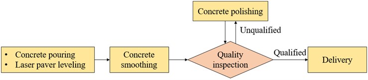
Fig. 2Construction site
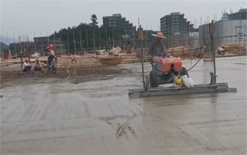
a) Concrete pouring with a laser paver
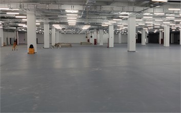
b) Super-flat floor to be delivered
2.2. Method of flatness detection
As specified in Code for acceptance of constructional quality of concrete structures (GB 50204-2015) [2], the flatness of cast-in-place concrete surface is measured manually by 2-m ruler and feeler gauge [3]. As shown in Fig. 3(a), by placing a 2-m ruler on the floor, the gap between ruler and floor can be measured by a gauge. Allowable deviation specified in this Code is 8 mm. Notably, it may be more stringent in specific projects.
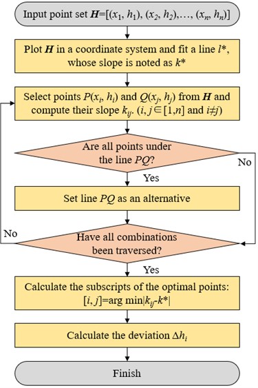
In order to simulate the ruler detection in point cloud obtained by TLS, a TLS-based flatness detection algorithm has been proposed, as shown in Fig. 4. The implementation of the algorithm includes 7 steps: 1) Extract the coordinates of a 2-m length point set from point cloud, where is the distance along the ruler direction and is the corresponding elevation; 2) Plot in a coordinate system and fit a line to describe the trend of this ground profile, whose slope is notes as , as shown in Fig. 3(b); 3) Select a pair of points and from to form a line , whose slope is noted as ; 4) Set line as an alternative of ruler only when all points of ground profile is below ; 5) Repeat steps 3)~4) until all combinations of have been traversed; 6) There may be more than one set as alternatives of ruler after traversing all the points, and the one with slope closest to the ground trend is considered to be the best option; 7) The gap between ruler and ground can be easily calculated when the ruler is determined, as shown in Fig. 3(c).
Fig. 3Flatness detection with ruler
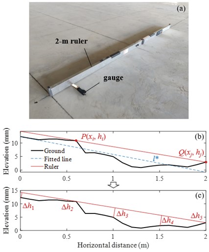
Fig. 4TLS-based algorithm for flatness detection
2.3. Verification of the algorithm
Two comparison experiments have been carried out to verify the accuracy of the proposed algorithm. At first, a 2 m×4 m grid was drawn on the emery floor to locate the measurement positions of 2-m ruler and TLS-based algorithm. Fig. 3(a) illustrated the measurement of grid edge by a ruler, and the maximum gap measured by gauge was used as an indicator of deviation. As it did, the same program was executed 18 times at different positions along the grid horizontally, vertically, and diagonally. Accordingly, ground profiles at same positions were extracted from point cloud for the flatness detection of TLS-based algorithm. Fig. 5 shows the positioning flatness deviation detected by 2-m ruler and TLS, in which the error of TLS was defined as Eq. (1). It can be seen that the detection error of TLS was within ±35 % when the tolerance was set to 4 mm:
where is the error of the th detection; is the deviation detected by TLS-based algorithm; is the deviation manually detected by 2-m ruler; is the flatness tolerance for construction acceptance and was taken as 4 mm in this paper.
However, it is more common to use the statistic parameter like pass rate as an assessment in construction acceptance. The flatness tolerance was set to 4 mm and those exceeding the limit were considered unqualified. Table 1 is the pass rate of a 12 m×12 m area detected by 2-m ruler and TLS-based algorithm. Specifically, the ruler has taken 99 detections at random positions for the calculation of pass rate. The projection of the ground is a 2D plane, so TLS-based detection was more precisely divided into row detection and column detection corresponding to the two axes of the plane. We can see from the results that the difference of pass rate detected by two methods was within ±1 %.
Fig. 5Positioning flatness deviation detected by 2-m ruler and TLS-based algorithm
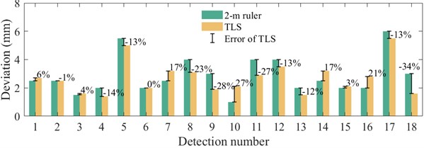
Table 1Pass rate detected by 2-m ruler and TLS-based algorithm
Random detection by 2-m ruler | Row detection by TLS | Column detection by TLS | |
Pass rate | 92.9 % | 93.9 % | 92.6 % |
3. Flatness detection of a super-flat emery floor
3.1. Introduction of scanning
The TLS-based method has been used for construction flatness detection of a super-flat emery floor. At first, a terrestrial laser scanner Trimble TX6 as shown in Fig. 6(a) was used to obtain the point cloud of emery floor, whose maximum measuring range is 80-120 m. Notably, there would be measurement blind spots due to the presence of structural columns, so a total of seven scanning stations were set to make the point clouds comprehensive. After that, point clouds of multiple stations were spliced together to form a floor model as shown in Fig. 6(b), with a scanned area of 83.0 m×80.0 m.
4. Results of flatness detection
Fig. 7 shows the floor plan with axes, and neighboring axes are generally spaced 12m apart while in some places they are smaller. Taking the square area between neighboring axes as statistical unit and averaging the row detection and column detection results as illustrated in Table 1, the pass rate of each area was labeled on the plan. We have measured most areas of this floor, and the areas not labeled were stairs, bathrooms, or places for construction equipment during scanning. It can be seen from the results that the highest pass rate is 94.1 % (E-F axes × 1-2 axes) and the lowest is 60.8 % (E-F axes × 7-8 axes), with the majority of areas having a pass rate above 70 %.
Fig. 6Scanning of super-flat emery floor
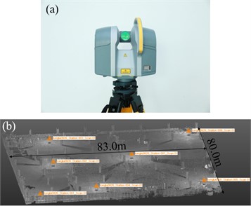
Fig. 7Floor plan with pass rates
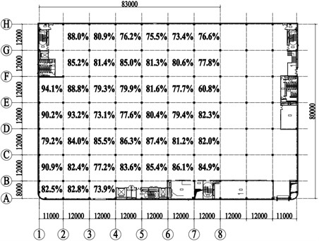
Fig. 8 shows the elevation map and detailed flatness detection results for D-E axes × 1-2 axes. In Fig. 8(a), taking the mean value of elevation as reference plane, the elevation range of this area is between ±12 mm. In Figs. 8(b) and 8(c), pass rates were 90.0 % for row detection and 90.4 % for column detection, which were almost the same. For better visualization, unqualified areas were marked in red, which could be used as a guide for concrete polishing as described in Fig. 1. The maximum difference of elevation in this area is more than 20 mm but the pass rate is still above 90 %, that’s because the flatness specified in Code is a local indicator, mainly related to variations of elevation within local area.
Fig. 9 is the elevation map and detailed flatness detection results for B-C axes × 3-4 axes. Obviously, the pass rate for row detection is significantly lower by about 8 % than pass rate for column detection. The elevation map in Fig. 9(a) shows the left-high and right-low trend with a raised post pouring strip at 6 m. As a result, when row detection was employed the ruler had to cross the strip, resulting in many unqualified areas as shown in Fig. 9(b). When column detection was employed, the strip was parallel to the ruler and had little contribution to the non-fatness. In summary, the method specified in Code is one-dimensional for flatness detection, but the floor surface is a two-dimensional plane. The pass rate will be significantly directional like the elevation trend.
Fig. 8D-E axes × 1-2 axes detection results by TLS-based algorithm
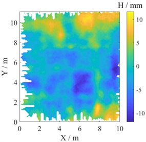
a) Elevation map
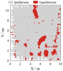
b) Row detection with the pass rate: 90.0 %
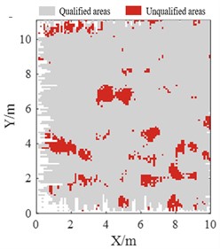
c) Column detection with the pass rate: 90.4 %
Fig. 9B-C axes × 3-4 axes detection results by TLS-based algorithm
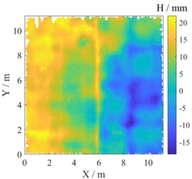
a) Elevation map
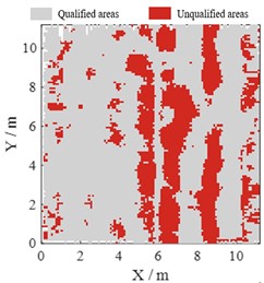
b) Row detection with the pass rate: 73.2 %
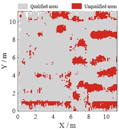
c) Column detection with the pass rate: 81.3 %
5. Conclusions
To solve the time-consuming and laborious problem of traditional method based on ruler and gauge, and extend the application of TLS in high-precision detection of large-scale construction projects, an efficient, full-coverage and intelligent TLS-based flatness detection method applicable to large-scale floors has been presented in this paper to help with the acceptance of emery floor. At first, we introduced the procedures of TLS-based algorithm, which can find the optimal position of ruler above the ground profile. Two comparison experiments have been carried out to verify the accuracy of the proposed algorithm. In positioning flatness detection, the detection error of TLS was within ±35 % when the tolerance was set to 4 mm. As for the random flatness detection, the pass rates detected by two methods were within ±1 %. So, it can be concluded that TLS-based method proposed in this paper has high detection accuracy.
The TLS-based method has been used for construction flatness detection of a super-flat emery floor. Floor plan labeled with pass rates can be easily obtained with the highest pass rate of 94.1 % and lowest pass rate of 60.8 %. Further, color maps marked with unqualified areas are presented and can be used as a guide for concrete polishing. By comparing row detection and column detection results, the pass rate is significantly directional like the elevation trend.
References
-
“Concrete industrial ground floors: a guide to design and construction,” 4th ed., Blackwater, Camberley, Surrey: The Concrete Society, 2016.
-
“Code for acceptance of constructional quality of concrete structures,” China Architecture & Building Press, Beijing, China, 2015.
-
D. Li et al., “A deep learning-based indoor acceptance system for assessment on flatness and verticality quality of concrete surfaces,” Journal of Building Engineering, Vol. 51, p. 104284, Jul. 2022, https://doi.org/10.1016/j.jobe.2022.104284
-
M.-K. Kim, Q. Wang, and H. Li, “Non-contact sensing based geometric quality assessment of buildings and civil structures: A review,” Automation in Construction, Vol. 100, pp. 163–179, Apr. 2019, https://doi.org/10.1016/j.autcon.2019.01.002
-
M.-K. Kim, H. Sohn, and C.-C. Chang, “Automated dimensional quality assessment of precast concrete panels using terrestrial laser scanning,” Automation in Construction, Vol. 45, pp. 163–177, Sep. 2014, https://doi.org/10.1016/j.autcon.2014.05.015
-
Q. Wang, M.-K. Kim, H. Sohn, and J. C. P. Cheng, “Surface flatness and distortion inspection of precast concrete elements using laser scanning technology,” Smart Structures and Systems, Vol. 18, No. 3, pp. 601–623, Sep. 2016, https://doi.org/10.12989/sss.2016.18.3.601
-
F. Bosché and E. Guenet, “Automating surface flatness control using terrestrial laser scanning and building information models,” Automation in Construction, Vol. 44, pp. 212–226, Aug. 2014, https://doi.org/10.1016/j.autcon.2014.03.028
-
D. Li, J. Liu, L. Feng, Y. Zhou, P. Liu, and Y. F. Chen, “Terrestrial laser scanning assisted flatness quality assessment for two different types of concrete surfaces,” Measurement, Vol. 154, p. 107436, Mar. 2020, https://doi.org/10.1016/j.measurement.2019.107436
-
P. Tang, D. Huber, and B. Akinci, “Characterization of laser scanners and algorithms for detecting flatness defects on concrete surfaces,” Journal of Computing in Civil Engineering, Vol. 25, No. 1, pp. 31–42, Jan. 2011, https://doi.org/10.1061/(asce)cp.1943-5487.0000073
About this article

We would like to thank Tutor Yifang Huang at the Training Platform of Construction Engineering at the Polytechnic Institute of Zhejiang University, for her help in the experiments of this paper.
The datasets generated during and/or analyzed during the current study are available from the corresponding author on reasonable request.
The authors declare that they have no conflict of interest.
