Abstract
This paper studies static test methods and test loads of Carbon Fiber Reinforced Polymer (CFRP) wing-box, analyzes the test results, and compares the test results of T800 CFRP wing-box from HENGSHEN Co., LTD and TORAY. It comes out that the stiffness of the T800 CFRP wing-box from HENGSHEN is equivalent with that of TORAY, while the strength meets the structural design requirements, which can be applied on the scheduled aircraft structure for further verification.
1. Introduction
The applications of composites in military and civilian aircraft are in a rapid increase trend with the transition from secondary load-bearing structures to main load-bearing structures. And composites have been applied on vertical tails, flat tails, and even wings in recent years [1].
There are many studies on mechanical properties of composite reinforced wall plates but limited studies on the wing-box section of aircraft [2-5]. By applying bending moment and torque to the wing-box section of aircraft, the response state of the stiffened plates under compression and shear loads can be observed more clearly [6-8].
The wing-box test is an important part of the structural level verification of the T800 CFRP following the mechanical performance, plate stability, and other typical component tests of it [9]. It is possible to further evaluate the structural molding process of carbon fibers and the related resin systems, as well as the drilling process characteristics of CFRP in the manufacturing and assembling processes. The static test on wing-box is to verify the structural performance and strength for an evaluation basis for the application of domestic CFRP in actual aircraft structures.
We have already carried out the static test using AC531/T800 composites for wing-box. In this static test, we use AC531/T800 carbon-fibre composites for wing-box. And the two tests are with the same configuration, also the test method and applied load are also the same, which provides a reference for the evaluation of T800 CFRP from HENGSHEN Co., LTD.
2. Test piece and test method
2.1. Test piece
The wing-box used for static test is the simulation of the structure between the 6th and 7th ribs of a certain type of aircraft’s tail. The wing-box consists of upper and lower wall plates, two plain ribs, two end ribs and two beams. Wall plates are of AC531/T800 composite reinforced structure, and their material properties are shown in Table 1. The beams are made by 7B04 material machine with I-shaped profile. The end ribs are made by LC4CS composite machine with П-shaped profile. The plain ribs are 2B06 sheet-metal ribs with П-shaped profile. The material properties of 7B04, Lc4CS and 2B06 are shown in Table 2.
Table 1Material property of AC531/T800
AC531/T800 | / MPa | / MPa | / MPa | / MPa | |
147000 | 8630 | 4400 | 0.33 | 2550 | |
/ MPa | / MPa | / MPa | / MPa | ||
1400 | 60 | 200 | 95 |
Table 2Material property of 7B04, LC4CS and 2B06
Material | / MPa | / MPa | |
7B04 | 70000 | 0.3 | 530 |
LC4CS | 70000 | 0.3 | 530 |
2B06 | 70000 | 0.3 | 430 |
2.2. Test method
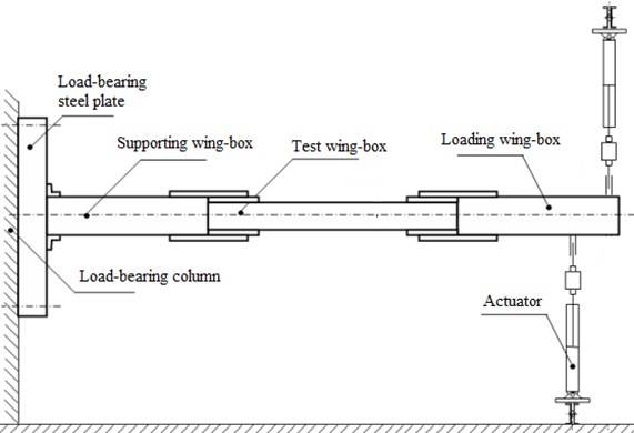
As shown in Fig. 1, the test method is followed: The two ends of the wing-box for test are mechanically connected to the loading wing-box and the supporting wing-box respectively, and the two wing-boxes are metal structures. The supporting wing-box is connected to the load-bearing thick steel plate by angle joint coin, and fixed to the load-bearing column by the thick steel plate. We set six loading points on the loading wing-box, and the actuator controlled by the coordinated loading control system is used to apply a given load to each loading point. And the load is transferred from the loading wing-box to the test wing-box.
Fig. 1Schematic diagram of wing-box test installation and loading
2.3. Test equipment
MOOG16 multi-channel coordinated control system was adopted as the control system. The system can set out-poor and over-limit according to the test requirements and modify the test parameters to obtain the required control results. The control system has an accuracy of 1%FS and a linearity of 0.5%FS.
ST24 data acquisition system was used. During the test, 10 acquisition channels can be selected for real-time data display. After the test, the measurement results of the acquisition channel can be saved and output. The system accuracy is 1%FS, and the linearity is 0.5%FS.
3. Test situation and result analysis
3.1. Test process
The 100 % design load for the flat-tailed wing-box is 34911.604 Nm, 5224.273 Nm. We distribute the design load equivalently to each loading point on the loading wing-box, and the load values corresponding to 100% of the design load at each loading point are shown in Table 3. Positive loads are upward acting loads while negative loads are downward acting loads.
Table 3Load value at each loading point corresponding to 100 % design load of the flat-tailed wing-box
Loading point | 1 | 2 | 3 | 4 | 5 | 6 |
Load value (N) | 48663.6 | 49357.4 | 36254.4 | –36254.4 | –49357.4 | –48663.6 |
We conduct 6 7% and 100 % design load tests respectively on the wing-box. In the 67 % design load test, when the load reaches 67 % of the design load, we keep the load for 30 seconds as required, and there is no residual deformation of the flat-tailed wing-box after unloading; in the load capacity test of 100 % design load, when the load reaches 100 %, we keep the load for 3 seconds as required, and then unload it to zero, and also there is no residual deformation found after unloading. Non-destructive testing is carried out after these tests and no damage is found.
And then we conduct destructive testing on the wing-box. When we put the load to 110 % of the design load, the lower wall plate of the wing-box breaks down as shown in Fig. 2(a). From the fracture surface, the failure begins with the rupture of the connecting holes between the two ends of the skin and the beam, which is unexpected. The reason for this damage pattern could be the poor assembly quality of the wing-box, the abnormal force transfer between the skin and the beam [6]. Also, insufficient margins of the connection holes could be an issue.
Fig. 2(b) shows the damage pattern of the wing-box made by fibers from TORAY, which has the same dimensions and loads with the CFRP wing-box as mentioned before. The damage pattern is the destabilization damage of the upper wall plates, and the damage load is 124 % of the design load.
Fig. 2Damage mode of T800 wing-box after destruction
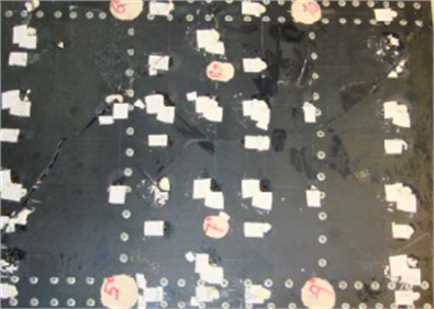
a) The lower surface of T800 wing-box from HENGSHEN after destruction
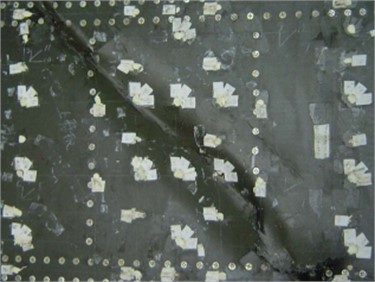
b) Damage pattern of the T800 wing-box from TORAY – destabilization of the upper wall plate
3.2. Displacement measurement results analysis
The displacement measurement points of the flat-tailed wing-box are arranged on the lower wall plate of the wing-box. As shown in Fig. 3, there are 12 displacement measurement points, among which points 1 and 2# measurement points are on the loading wing-box, and the others are on the test wing-box. For these points, only their displacements perpendicular to the direction of the wall plate are measured.
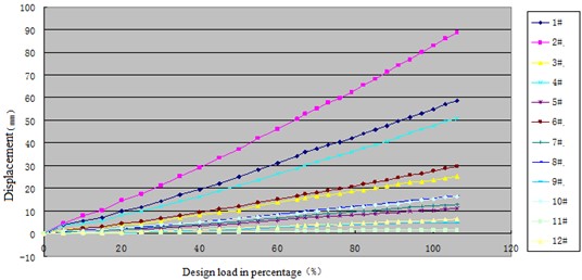
The displacement-load curves of the T800 drop-tail wing-box from HENGSHEN Co. LTD (wing-box A) and the T800 drop-tail wing-box from TORAY (wing-box B) are shown in Figs. 4 and 5 respectively. But the displacements at points 1 and 2 of wing-box A are not measured. However, by comparing them with the other displacement measurement points, it is easy to find that there is little difference between the displacements of wing-box A and wing-box B at the same position.
Due to the high accuracy and linearity of the measurement system, the measurement data have the same accuracy and high confidence degree.
Fig. 3Positions of the wing-box displacement measurement points
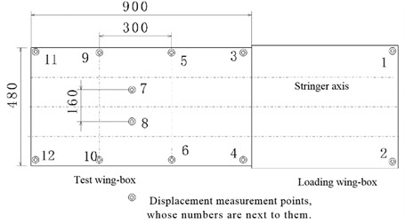
Fig. 4Displacement-load curves of the wing-box A
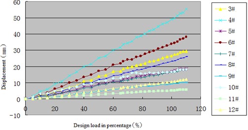
Fig. 5Displacement-load curves of the wing-box B
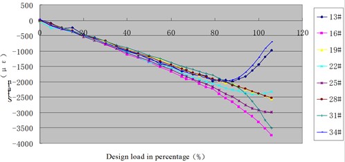
3.3. Stain measurement results analysis
Fig. 6 shows the layout of strain gauges on the outer surfaces of the upper and lower wall plates of the flat-tail wing-box. The layout of the strain gauges in wing-box A is the same as wing-box B, but numbers are different. In this paper, the distribution and variation of strain values in the 0° layup direction (longitudinal) on the outer surface of the upper and lower wall plates of wing-box are mainly examined. The strains of the lower wall plates of wing-box were investigated. Under bending and torsion loads, the upper wall plate of the wing-box is subjected to a combined effect of longitudinal tensile stress and shear stress.
The buckling situations of the two vertical-tail wing-boxes were compared. The longitudinal strain variation curves of the strain measurement points on the three central sections of the upper wall plates from two wing-boxes until failure are shown in Figs. 7 and 8 respectively. We can see that wing-box A begins to buckle in the middle of the wall plate with 70 % design load, while wing-box B begins to buckle until 76 % design load. This difference may be attributed to the poor assembly of the T800/5405 vertical-tail wing-box.
Due to the high accuracy and linearity of the measurement system, the measured strain data have high reliable and accuracy.
Fig. 6Layout of strain gauges on the outer surface of the upper and lower wall plates of wing-box A. Note: The strain gauges of the upper and lower wall plates of the wing-box are fixed symmetrically. The strain gauges of the lower wall plate are numbered as the strain gauge number of the upper wall plate plus 100
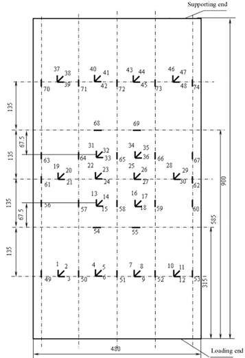
Fig. 7Strain-load variation curves of the strain measurement points on the three central sections of the upper wall plate of wing-box A
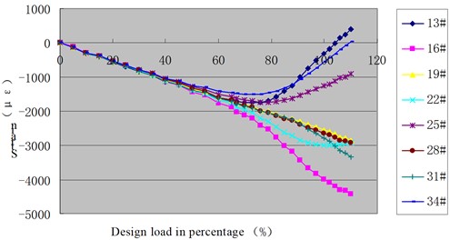
Fig. 8Strain-load variation curves of the strain measurement points on the three central sections of the upper wall plate of wing-box B
4. Conclusions
Compared the two wing-boxes, the displacement and overall strain level of the upper and lower wall plates are almost the same, indicating that there is no significant difference in stiffness or modulus between T800 CFRP from HENGSHEN Co., LTD and T800 CFRP from TORAY.
When the T800 CFRP wing-box test is loaded to 110 % of the design load, the connection nail hole between the lower wall plate skin and the beam breaks down, which is an unexpected damage pattern. The normal damage pattern is the buckling of the upper wall plate. Therefore, we get the preliminary opinion that the reason for this damage is related to the poor quality of the assembly (including the drilling of the loading wing-box and the supporting wing-box), and the accurate reasons are to be further analyzed.
The results of the static tests show that all test pieces have passed the design load assessment, and the static strengths meet the design requirements, which provides a basis for further practical structural application of T800 CFRP.
References
-
H. L. Tekinalp et al., “Highly oriented carbon fiber-polymer composites via additive manufacturing,” Composites Science and Technology, Vol. 105, pp. 144–150, Dec. 2014, https://doi.org/10.1016/j.compscitech.2014.10.009
-
A. C. Orifici, I. O. de Zarate Alberdi, R. S. Thomson, and J. Bayandor, “Compression and post-buckling damage growth and collapse analysis of flat composite stiffened panels,” Composites Science and Technology, Vol. 68, No. 15-16, pp. 3150–3160, Dec. 2008, https://doi.org/10.1016/j.compscitech.2008.07.017
-
J. Bertolini, B. Castanié, J.-J. Barrau, and J.-P. Navarro, “An experimental and numerical study on omega stringer debonding,” Composite Structures, Vol. 86, No. 1-3, pp. 233–242, Nov. 2008, https://doi.org/10.1016/j.compstruct.2008.03.013
-
C. Zhao, J. Yin, Y. Chen, J. Gu, H. Du, and Y. Cheng, “Research on buckling load prediction of composite stiffened plates based on BP neural network,” Journal of Physics: Conference Series, Vol. 1576, No. 1, p. 012032, Jun. 2020, https://doi.org/10.1088/1742-6596/1576/1/012032
-
B. Hu, X. Chen, F. Deng, and X. Sun, “Evaluation of failure criteria for residual tensile strength of composite laminates with circular holes,” Vibroengineering Procedia, Vol. 49, pp. 212–219, May 2023, https://doi.org/10.21595/vp.2023.23348
-
L. Dang et al., “Buckling and post buckling of composite multi-wall box section under bending-torsion coupled loads,” Chinese Quarterly of Mechanics, Vol. 43, No. 2, pp. 271–280, 2022, https://doi.org/10.15959/j.cnki.0254-0053.2022.02.007
-
J. L. Tan, “Bending stability analysis and virtual experiment design of typical composite wing box,” Harbin, China: Harbin Institute of Technology, 2020.
-
M. Zhu, G. Liu, and J. Dang, “Study on properties and application of high temperature cured carbon fiber composites for main bearing structure of tail box section,” Aerospace Materials and Technology, Vol. 49, No. 2, pp. 82–85, 2019.
-
J. Zhou and H. Xue, “Research on assembly technology of composite tail wing box sections,” Manufacture and Upgrading Today, Vol. 2021, No. 12, pp. 81–82, 2021.
About this article

The authors have not disclosed any funding.
The datasets generated during and/or analyzed during the current study are available from the corresponding author on reasonable request.
The authors declare that they have no conflict of interest.
