Abstract
The design principles of strength test support methods for aircraft structural components were introduced in this paper. Aiming at the vertical tail static test of a certain type of aircraft, a supporting stiffness simulation method was invented, and a support fixture was designed. The supporting stiffness was accurately simulated by stiffness strength. The research results of this paper provide an important reference for the research of static test support methods for similar aircraft structural components.
1. Introduction
In the 21st century, the aviation industry has entered a stage of rapid development, and a large number of new aircrafts have been approved. In the structural selection or structural change stage of aircraft development, a large number of static strength and fatigue strength tests of structural components will inevitably be carried out [1]. In particular, static strength test, as the most basic and classical verification method of structural strength, directly affects the aircraft structural strength design process [2]. Unlike the full scale aircraft test, the component test needs to be mounted on a support fixture. Moreover, the way how the component was supported affects the stress distribution in the component. If the simulation is not accurate, it will cause huge differences in the stress characteristics, damage sites, and damage modes [3]. Therefore, how to simulate the boundary support conditions of the component has become the key to influence the results of the strength verification test [4].
2. Design principle and application of proposed support method in component test
Where available, component tests should be performed on the aircraft. Using the aircraft as a support for the test piece, applying loads to the test component and balancing loads to the rest of the aircraft, this kind of test is advantageous in terms of real connection and real force transmission [5]. However, at the stage of aircraft R&D, this idea simply cannot be realized. Therefore, the component test is generally fixed on a specially designed support fixture for the test, and the support fixture design principles are as follows [6]:
(1) the support fixture should maximize the simulation of the real use of aircraft components.
(2) the support fixture should maximize the simulation of the aircraft component stiffness, displacement, and the boundary conditions of the load.
(3) the support fixture cannot limit the reasonable deformation of aircraft components.
(4) the support fixture should regard the weight of aircraft components.
Generally, structures are categorized into static stable and unstable structures. Therefore, static test support methods for aircraft structural components can be categorized into static stable and unstable constraints accordingly.
In a static stable structure, the distribution of forces is only related to the relative geometrical positions of the components and the acting forces, allowing the internal forces of the components to be determined according to the static equilibrium conditions [7]. Therefore, in the design of fixtures with static stable constraints, the internal forces can be calculated according to the test loads and strength correction can be carried out. A general safety factor of not less than 2.5 is sufficient.
Aircraft structures are mostly complex static unstable structures. In addition to the establishment of equilibrium equations, it is also necessary to find out the forces on each component according to the deformation coordination conditions, i.e., the distribution of forces is also related to the stiffness and support conditions of each component itself. For static indefinite constrained component tests, commonly the transition segments are used for boundary support [8-9]. The structure of the transition segment is similar to the real aircraft structure with only local reinforcement, which leads to a long production cycle and high cost. Sometimes the cost of the transition segment is even higher than the test part. Therefore, it is of compelling engineering significance to research on simulation technology of supporting fixture stiffness distribution according to the “stiffness distribution principle” of the structure.
3. Stiffness simulation of the supporting fixture in the multi-joint suspended airfoil structure
The wing, horizontal tail, vertical tail and other airfoil structural components of most airplanes are connected to the fuselage with bolts through multiple sets of station joints. The structural components are subjected to shear loads perpendicular to the airfoil direction, and the station joints are subjected to both shear and bending loads. Therefore, there are two requirements for the supporting stiffness of the airfoil structure: shear stiffness and bending stiffness. A method of stiffness simulation is described below.
3.1. Requirements for the supporting stiffness
In a vertical tail static test of a certain type of aircraft, the vertical tail and fuselage are connected through three sets of station joints, and their theoretical supporting stiffness requirements are shown in Table 1. The supporting stiffness required in the test is very strict, that is, the stiffness value of each station of the support fixture is not more than 4 times of the theoretical stiffness, and the error of the stiffness ratio of each station is not more than 5 %.
In Table 1, 12700 position represents that the coordinate value of the station is 12700 mm, and so on.
Table 1The stiffness value of each station
Station | Item | Stiffness Value | Intersection coordinates / mm |
12700 position | shear stiffness | 1.07×10⁴ N/mm | ±120, 12700, 890 |
bending stiffness | 1.83×10⁹ N∙mm/rad | ||
13435 position | shear stiffness | 9.40×10³ N/mm | ±128, 13435, 890 |
bending stiffness | 2.28×10⁹ N∙mm/rad | ||
14050 position | shear stiffness | 5.76×10³ N/mm | ±115, 14050, 890 |
bending stiffnes | 1.72×10⁹ N∙mm/rad | ||
* is perpendicular to the airfoil direction, is along the counter-course direction, and is vertically upward. The coordinate origin is located at the nose of the aircraft | |||
3.2. Supporting fixture designing
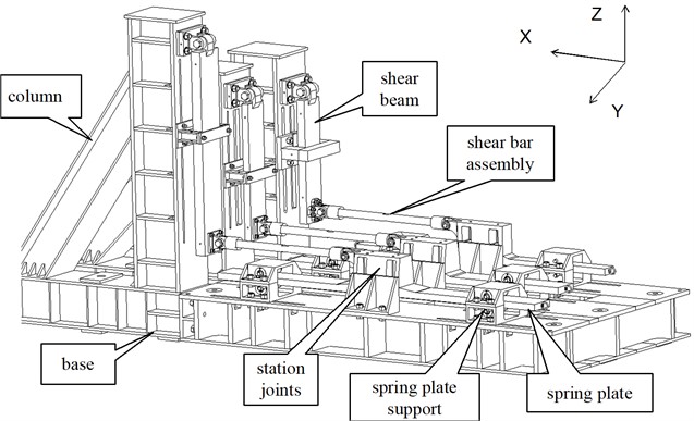
According to the test stiffness requirements of the fixture, the bending deformation of the spring plate was used to simulate the bending stiffness at the support, and the bending deformation of the shear beam was used to simulate the shear stiffness at the support. As shown in Fig. 1, three station joints are fixed to the spring plate, and the vertical tail is connected to the station joints by bolts. One end of the shear beam is connected to the column and the other end is connected to the shear bar through the loading seat. The connection between the shear bar and the station joints ,the loading seat are both hinge joints. The hinged connection can separate the deformation of each station joint under the action of unit bending moment and unit shear force , i.e., the -direction bending stiffness and -direction shear stiffness do not affect each other. The bending stiffness and shear stiffness of each station are designed separately to ensure that the bending stiffness ratio and shear stiffness ratio of each station meet the requirements. In order to adjust the stiffness, the spring plate support and the limit assembly were designed, and the spring plate support can slide along the length direction of the spring plate, and the limit assembly can slide along the length direction of the shear beam.
Fig. 1Supporting fixture of the experimental component
3.3. Supports fixture stiffness calibration
After the design and processing of the vertical tail supporting fixture were completed, the stiffness calibration test of the fixture was performed in order to ensure that the fixture simulation is accurate.
3.3.1. Stiffness calibration test
The calibration fixture of the test is shown in Fig. 2. The calibration beam is connected to the station joint by bolts, and there is a cleat between the station joint and the calibration beam, through which the bending deformation can be enlarged and measured.
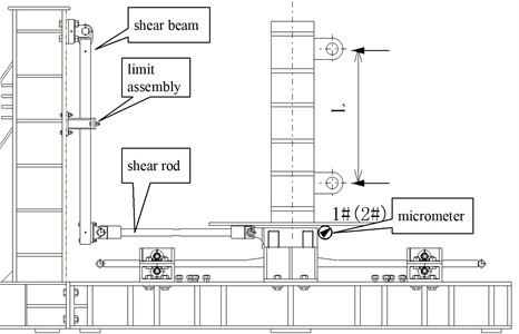
The method of the stiffness calibration test is shown in Fig. 3, and the test loads are applied by means of horizontally mounted actuators. Two actuators are arranged at the top and bottom of each station, and by adjusting the loads of the two actuators, pure bending and pure shear loads can be applied to the joints of the station.
3.3.2. Displacement measurement for bending stiffness calibration
3.3.2.1. Displacement measurement procedure in the stiffness calibration test
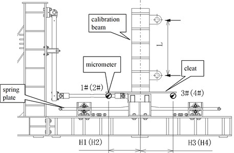
As shown in Fig. 4, during the bending stiffness calibration, in order to obtain the turning angle of the station joints, four micrometers were arranged at each station to measure the -direction displacements (1 to 12) at both ends of the cleat in Fig. 2. A total of 12 micrometers were arranged.
Fig. 2Test calibration fixture
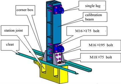
Fig. 3The method of the stiffness calibration test
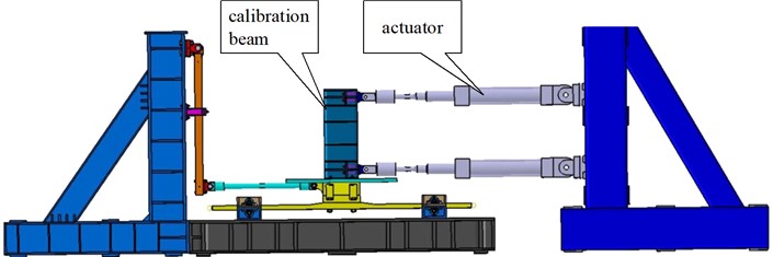
Fig. 4Layout of displacement measurement for bending stiffness calibration
3.3.2.2. Displacement measurements for shear stiffness calibration
For the shear stiffness calibration, two micrometers were arranged at each station to measure the -direction displacement (1 to 6) of the station joints, as shown in Fig. 5. A total of 6 micrometers were arranged.
Note that Fig. 4 shows the layout of the displacement measurement determined by bending stiffness, and Fig. 5 shows the displacement measurement arranged by shear stiffness.
3.3.3. Results of supports fixture stiffness calibration
In this paper, the displacement data at 100 % limiting load is used for linear fitting to obtain the slope of each displacement measurement point, and the corner is calculated according to Eqs. (1) to (3):
where, represents the rotation angle of the 12700 station joint, and 12700 indicates the coordinates of the station joint. / represents the same meaning.
Fig. 5Layout of displacement measurements for shear stiffness calibration
The bending stiffness is calculated by Eq. (4):
where is the -direction supporting moment of the stationary joint at 150 % limiting load.
The shear stiffness is calculated by Eq. (5):
where is the -directional support reaction force of the stationary joint at 150 % of the limiting load.
The calibrated stiffness results are shown in Table 2. It can be seen that the stiffness value of each station of the support fixture is less than 4 times of the theoretical stiffness, and the error of the stiffness ratio of each station of the support fixture is less than 5 %, which satisfies the requirement of stiffness.
3.4. Implementation results
MOOG16 multi-channel coordinated control system was adopted as the control system, and T24 data acquisition system was adopted as the measurement system. They both have an accuracy of 1%FS and a linearity of 0.5%FS. In addition, the micrometer has an accuracy of 0.1%FS and a linearity of 0.1%FS. Therefore, the measured data are of equal precision.
Table 2Comparison of stiffness calibration test results with theoretical stiffness
Stiffness type | Position | Theoretical Stiffness | 4 times theoretical stiffness | Theoretical stiffness ratio | Calibration stiffness | Calibration stiffness ratio | Difference |
Bending stiffness | 12700 | 1.83E+09 | 7.32E+09 | 1.064 | 5.36E+09 | 1.029 | –3.32 % |
13435 | 2.28E+09 | 9.12E+09 | 1.326 | 6.94E+09 | 1.331 | 0.39 % | |
14050 | 1.72E+09 | 6.88E+09 | 1.000 | 5.21E+09 | 1.000 | 0.00 % | |
Shear stiffness | 12700 | 1.07E+04 | 4.28E+04 | 1.86 | 21621 | 1.86 | 0.13 % |
13435 | 9.40E+03 | 3.76E+04 | 1.63 | 18667 | 1.61 | –1.60 % | |
14050 | 5.76E+03 | 2.30E+04 | 1.00 | 11624 | 1.00 | 0.00% | |
Note 1: The unit for bending stiffness is N·mm/rad and for shear stiffness is N/mm Note 2: The stiffness ratio is calculated based on 14050 position | |||||||
In the 150 % limiting load test of a certain aircraft composite full-size vertical tail static test, the calibrated strain gauges on the fixture are used to speculate the real loading condition of each station of the test piece, and the error is controlled within 5 %. At the same time, the measured strain values on the vertical tail are consistent with the theoretical calculation results, which indicates that the fixture stiffness simulation results are real and accurate, and supports the correct and feasible fixture stiffness simulation method.
4. Conclusions
In this study, the structural form of joint and spring plate is adopted, and by adjusting the design parameters of the spring plate (hinge support bar spacing, thickness and width of the spring plate), the bending stiffness ratios of the three station joints of the vertical tail are made to meet the requirements of the test design (with an error of less than 5 %). The simulation of the bending stiffness of the support fixture on the vertical tail support is realized, which breaks through the key technology of the support fixture stiffness simulation. The test results show that the stiffness simulation meets the test requirements.
This proposed supporting stiffness simulation technique can not only realize the stiffness simulation of vertical tail support fixture, but also can be applied to the support fixture stiffness simulation of multi-joint suspension airfoil structural component test.
References
-
B. Hu, X. Sun, L. Cheng, and F. Deng, “Research and application of ultra-high pressure control system in strength tests,” Vibroengineering Procedia, Vol. 42, pp. 118–124, May 2022, https://doi.org/10.21595/vp.2022.22669
-
B. Hu, L. Cheng, X. Sun, and F. Deng, “Design technique of the test static for large curvature composite radome,” in Journal of Physics: Conference Series, Vol. 2553, No. 1, p. 012019, Aug. 2023, https://doi.org/10.1088/1742-6596/2553/1/012019
-
Bing Liu, “Research and application of statically determinate support and restraint technology for static test on large aircraft,” Science Technology and Engineering, Vol. 19, No. 11, pp. 286–291, 2019, https://doi.org/10.7527/s1000-6893.2022.25816
-
Yuanli Zhang, “Research and application of design method of support fixture for ground static test of landing gear connection area,” Engineering and Test, Vol. 63, No. 4, pp. 62–64, 2023.
-
Bin Wang, Jianjun Zheng, Wei Liu, and Mengmeng Wang., “Optimum design method for static test of aircraft wing segment,” Acta Aeronautica et Astronautica Sinica, Vol. 44, No. 18, pp. 179–190, 2023, https://doi.org/10.7527/s1000-6893.2022.28065
-
Baoping Qiang, Ground Testing for Aircraft Structure. Beijing, China: Aviation Industry Pres, 2014.
-
Feng Xia and Jiachen Mu, “The support and loading technology of landing gear with multi-wheels and multi-struts for full-scale aircraft static test,” Science Technology and Engineering, Vol. 18, No. 30, pp. 238–244, 2018, https://doi.org/10.7527/s1000-6893.2019.23332
-
Pengfei Yang, Mengsi Fu, and Yi Wang, “Research on the design method and application of support fixture for static test of wing-body assemblies,” Engineering and Test, Vol. 62, No. 1, pp. 59–61, 2022.
-
Botao Hu, Hui Zhang, and Lei Zhang., “Static test technology of the composite leading edge considering large deformation of the wing,” Fiber Composites, Vol. 39, No. 151, pp. 30–36, 2022, https://doi.org/10.1515/secm-2020-0023/html
About this article

The authors have not disclosed any funding.
The datasets generated during and/or analyzed during the current study are available from the corresponding author on reasonable request.
The authors declare that they have no conflict of interest.
