Abstract
The energy conversion efficiency of wave energy device is one of the key problems in the large-scale utilization of wave energy. The study of the maximum output POWER of PTO (Power-Take-Off) system provides a theoretical reference for the efficient utilization of energy. In this paper, genetic algorithm and adaptive differential evolution algorithm based on neighborhood search are used to optimize the two-objective multi-order differential equations for the maximum output power of PTO system, and the global optimal solution is obtained. Compared with the traversal algorithm, the algorithm involved in this paper is efficient and the optimal output power obtained can provide a scientific basis for the structural optimization design and material selection of the wave energy device.
1. Introduction
Nowadays, people pay more and more attention to the development of new energy. As an important marine renewable energy, wave energy is widely distributed and abundant in reserves. The energy conversion efficiency of wave energy device is one of the key problems in the large-scale utilization of wave energy. The device generally involves two kinds of motion forms: heave and pitch.
At present, the time-frequency comprehensive analysis method is often used for the sag motion of PTO systems. Charitini et al. [1] converted the impulse response function in the float dynamic equation into state space through frequency domain identification, so as to realize convolutional substitution, accurately simulated the float's force in waves and analyzed its dynamic performance carefully, but did not systematically give the influence of the oscillator on the model. Liu et al. [2] verified the accuracy of Simulink model by comparing with the time domain calculation results of AQWA based on the converted float dynamic equation in time domain. Based on the superposition model, Ma et al. [3] fitted the characteristic period corresponding to the maximum total power generation of the integrated system in irregular waves.
Coupling analysis is often involved in the pitch motion of PTO systems. Shen et al. [4] established the hydrodynamic model and coupled motion equation of the pitching float, Kang et al. [5] studied the frequency, magnitude and other important characteristics of the dynamic water pressure at different observation times by using discrete wavelet packet transformation. On this basis, for the power calculation of oscillating float wave energy device, Wang et al.[6] adopted simulated annealing algorithm to reduce the time complexity and innovatively proposed an improved particle swarm optimization algorithm to provide guidance for calculating the maximum output power of the system under complex motion.
To sum up, when calculating the output power of wave energy devices, most scholars adopted the time-frequency comprehensive analysis method to simulate the damping of ocean waves by using the single-wave first-order linear excitation, so as to predict the maximum power generation [7-8]. Through analysis, the prediction accuracy of this method depends on the stability of the coupling system. Based on the above research methods, this paper intends to solve the maximum output power of the system by analyzing the moment of inertia and the comprehensive moment and establishing multivariate second-order differential equations based on genetic algorithm.
The follow-up arrangement of this paper is as follows: The first part mainly introduces the wave energy device, and establishes the heave-pitch motion model and the system output power optimization model. The second part mainly calculates the motion parameters and output power of the system. The third part summarizes the scheme.
2. Materials and methods
2.1. Wave energy device
The structure diagram of the wave energy device is quoted from question A of the 2022 Higher Education Society Cup National College Students Mathematical Contest in Modeling, as shown in Fig. 1 and Fig. 2. The float is composed of a cylindrical shell and a conical shell with uniformly distributed mass. The connecting part of the two shells has a spacer layer, which is used as the support surface of the installation of the central shaft; the vibrator is a cylinder threaded through the central shaft and connected to the base of the central shaft by a PTO system (including springs, dampers). Under the action of the wave, the float moves and drives the vibrator to move, and through the relative motion of the two, the damper is driven to do work, and the work done is output as energy. The system parameters are shown in Table 1.
Fig. 1Wave energy device
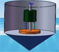
Fig. 2Heave-pitch PTO system
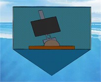
Table 1PTO system parameter table
Float mass | 4866 kg | Height of vibrator | 0.5m |
Float bottom radius | 1 m | Density of seawater | 1025 kg/m 3 |
Height of float cylinder | 3 m | Gravity acceleration | 9.8 m/s 2 |
Height of float cone | 0.8 m | Spring stiffness | 80000 N/m |
Mass of vibrator | 2433 kg | Original length of spring | 0.5 m |
Radius of vibrator | 0.5 m | Torsion spring stiffness | 250000 N·m |
Hydrostatic restoring moment coefficient | 8890.7 N·m | ||
2.2. Heave-pitch compound motion
2.2.1. Compound motion model of float-PTO-vibrator system
1) Calculate the moment of inertia of the vibrator:
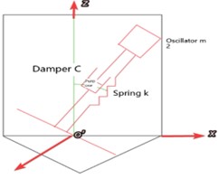
Considering that the vibrator is composed of two core components, spring and damper, the isolation modeling method is innovatively adopted in this paper, ignoring other external load effects of the vibrator, and focusing on analyzing the force of the core component, so as to approximate the operation of the vibrator in the sea wave. The vibrator model is shown in Fig. 3.
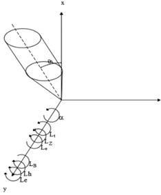
Let the vibrator rotates around the axis. The moment of inertia when it rotates laterally around the particle is:
where, is the mass of a solid cylinder, is the radius of the cylinder, and is the height of the cylinder.
It is known that the length of the spring in equilibrium is 0.298 m, and the distance from the barycenter of the vibrator to point C is:
From the axis theorem, the moment of inertia of the vibrator to point C is known:
Fig. 3Vibrator model
2) Calculate the moment of inertia of the float:
1. Calculation of the barycenter of the float. According to the symmetry, the barycenter of the float is on the axis, and the static moment about the axis is:
2. Calculate the moment of inertia of the system. Now the float is divided into three regions for integration:
To sum up, the moment of inertia of the float around the axis is:
3) Force analysis of system pitch motion:
1. Wave excitation torque: .
2. Wave damping torque: .
3. Still water recovery torque: .
4. Additional inertia torque: .
5. Spring torque: .
6. Rotational damping torque: .
Where, is the amplitude of wave excitation torque, and is the wave angular frequency. is the proportional coefficient of wave-making damping torque and float angular velocity, and is the angular velocity of the float. is the proportional coefficient between the still water restoring force and the float angle . is the additional inertial mass of the float, is the angular acceleration of the float along the rotating shaft. is the torsion coefficient of the spring, and are the angular displacement of the float and vibrator. is the rotational damping coefficient, and are the angular velocities of the float and vibrator.
As shown in Fig. 4. The isolation method is used to analyze the force of the system.
The dynamic equation of the system is:
Select the appropriate initial conditions:
Fig. 4Force analysis diagram of float isolation
2.2.2. Optimization model of system output power
1) Optimization objectives. The damping design of PTO system is carried out to maximize the output power of the system.
Linear damping applies instantaneous work:
Rotational damping applies instantaneous work:
The average output power of the objective function is obtained as follows:
2) Decision variables and constraints. Based on the optimization objective, the decision variables of PTO system are set as linear damping coefficient and rotational damping coefficient . The constraint condition is the variation interval of damping coefficient [0, 100000].
3) Model synthesis. To sum up, the dual-objective optimization model can be established as follows:
3. Results and analysis
3.1. Heave-pitch (angular) displacement and (angular) velocity
The following external load parameters are comprehensively considered: incident wave frequency, heave additional mass, pitch additional moment of inertia, heave wave damping coefficient, pitch wave damping coefficient, heave excitation force amplitude, and pitch excitation moment amplitude. The trajectory following of Matlab is used to draw the motion images of the float and the vibrator that are shown in Fig. 5 and Fig. 6.
Fig. 5Displacement image of the float and the vibrator
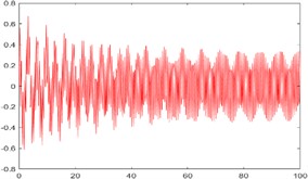
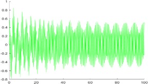
Fig. 6Angular displacement image of the float and the vibrator
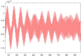
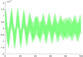
Observing the image, it is found that the displacement and angular displacement of the vibrator lag behind the float for half a period, and both of them gradually stabilize from the initial oscillation. For angular displacement, there is a small fluctuation around 80 s; however, the abnormal fluctuation occurs for a short time and the fluctuation value is small. To sum up, the composite moving image has a high fitting degree.
Calculation results of the float and the vibrator are shown in Table 2.
In the table, the left side of the dividing line is the motion parameter of the float, and the right side is the motion parameter of the vibrator. Through analysis, the heave (angular) velocity and pitch (angular) velocity of the float and vibrator all change with the period of time course, and the period is approximately 40 s; The pitch motion of the vibrator has less influence on the heave motion than that of the float. Therefore, in practical engineering, the float material can be optimized to enhance its anti-rotation damping performance, so as to improve the stability of the system.
Table 2Float and vibrator’s heaving and pitching (angle) displacement – (angle) velocity value
Time (s) | Heaving displacement (m) | Heaving speed (m/s) | Pitching angular displacement (rad) | Pitching angular speed (s-1) | ||||
Float | Vibrator | Float | Vibrator | Float | Vibrator | Float | Vibrator | |
10 | 0.12 | 0.09 | –0.34 | –0.53 | –0.59 | –0.01 | –0.10 | –0.10 |
20 | –0.21 | –0.37 | –0.99 | –0.18 | –0.14 | –0.14 | –0.27 | –0.03 |
40 | 0.02 | 0.01 | 0.35 | 0.54 | 0.26 | 0.03 | 0.11 | 0.10 |
60 | 0.27 | 0.44 | –0.16 | –0.21 | 0.89 | 0.09 | –0.45 | –0.46 |
100 | –0.13 | –0.24 | 0.33 | 0.49 | –0.31 | –0.03 | 0.92 | 0.09 |
3.2. System output power of compound motion
In this paper, genetic algorithm and adaptive differential evolution algorithm are used, combined with population size, crossover probability, fitness function, the calculation results are shown in Table 3.
Table 3Global optimal solution of PTO system with complex motion
Upper bound of system | Optimal damping coefficient / (N·s/m) | Global maximum output power / W |
The damping constant is 10000. The power exponent is 1. | 99632 | 382.1 |
4. Conclusions
In this paper, a two-objective optimization model is established based on PTO system, and the mechanical motion of complex system is decomposed into the independent motion of float and vibrator. The isolation method is used to calculate the force of the float and the vibrator respectively, and the corresponding multivariate second-order differential equations are established. Finally, based on adaptive differential evolution algorithm and genetic algorithm, the maximum average output power of PTO system in the complex motion of heave and pitch is obtained.
References
-
S. Charitini, G. Anders, and K. Eirini, “Fast time-domain model for the preliminary design of a wave power farm,” Renewable Energy, Vol. 219, No. Part 2, pp. 2–4, 2023.
-
Y. J. Liu, A. W. Peng, and M. Y. Huang, “Research progress on PTO system of ocean wave power generation device,” Journal of Solar Energy, Vol. 10, pp. 3–8, 2023, https://doi.org/10.19912/j.0254-0096.tynxb.2022-1229
-
Z. Ma, “Study on hydrodynamic characteristics of oscillating float wave power generation device,” Ocean University of China, 2013.
-
J. H. Shen, Z. J. Cai, and S. H. Zhou, “Design model and solution of wave energy maximum output power,” Mathematical Modeling and Application, Vol. 12, No. 1, pp. 27–33, 2023, https://doi.org/10.19943/j.2095-3070.jmmia.2023.01.04
-
H. B. Kang and H. K. Kim, “Wave data analysis for wave energy power in namae coast,” Applied Mechanics and Materials, Vol. 3546, pp. 672–674, 2014.
-
D. L. Wang, J. Li, and W. Yang, “Power calculation analysis and parameter design of oscillating float wave energy device,” Journal of Harbin Engineering University, Vol. 2, pp. 1–8, 2024.
-
Q. Zhang and Z. Meng, “Adaptive differential evolution algorithm based on deeply-informed mutation strategy and restart mechanism,” Engineering Applications of Artificial Intelligence, Vol. 126, No. Part C, pp. 3–18, 2023.
-
D. Zieliński and D. Grzechca, “The effect of cable aging on surge arresters designed by genetic algorithm,” Applied Sciences, Vol. 13, No. 20, pp. 3–7, 2023.
About this article

The authors have not disclosed any funding.
The datasets generated during and/or analyzed during the current study are available from the corresponding author on reasonable request.
The authors declare that they have no conflict of interest.
