Abstract
The body-in-white simulation model of a certain commercial vehicle was established to make a numerical analysis of the vehicle body static stiffness in this research. Meanwhile, the effectiveness of the simulation model was verified using the physical test of body-in-white static stiffness. Research results showed that the error of body-in-white static stiffness test and simulation analysis was within the range of ±10 %, which could reduce the test cost and guarantee the test precision. The research findings do provide a better application value and references for vehicle engineering developers.
1. Introduction
The load-supporting car body is mainly used in the modern automobile design to meet the requirements of light weight, namely, the car body almost loads all the bending loads and torsional loads. The static stiffness of the car body is an important index to measure the automobile load-carrying capacity, which has an important influence on the security, handling stability and NVH (Noise, Vibration and Harshness) performance of automobiles. Simulation test and bench test are mostly conducted on the body-in-white in the static stiffness research of the vehicle body [1-3].
In this paper, a simulation model of the body-in-white static stiffness of a certain commercial vehicle was established with the aid of computer simulation software, and the accuracy of the simulation model was tested and verified using the physical test. The research findings could be applied in the engineering development and are well worth promoting.
2. Computational modeling
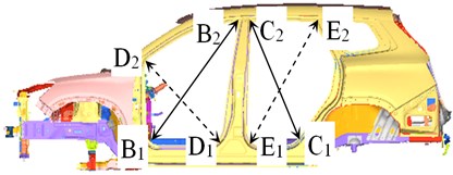
In the study of static stiffness of vehicle body, the body is often approximated as a linear system and simplified as a rectangular frame structure with longitudinal beams. Bending deformation occurs when the body bears bending loads [4, 5]. The body structural deformation under the bending working conditions was presented in Fig. 1, where A and B are constrained points of rear spring seats, C and D are constrained points of the mounting hole on the front suspension, and are the loading points of vehicle body, and the dotted line is the location after the loading deflection of the body structure. The bending stiffness of the body is defined as the ratio of the load to the corresponding displacement. The equation was presented as follows:
where, is bending stiffness, is the total load placed on the body, are the maximum deformation displacements of left longitudinal beam and right longitudinal beam in the direction respectively, , , , are the maximum deformation displacements of the projective points of A, B, C, D on the longitudinal beams in the direction respectively, is the distance between the maximum displacement location of the longitudinal beam deformation and CD end, and is the distance between front suspension and rear suspension.
Fig. 1Vehicle body structural deformation under bending working conditions
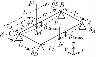
Fig. 2Vehicle body structural deformation under torsional working conditions
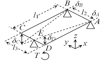
When the vehicle body bears the torsional load, torsional deformation of vehicle body would occur [6, 7]. The Vehicle body structural deformation under torsional working conditions was presented in Fig. 2, where A and B were constrained points of rear spring seats, E is the constrained point of the front suspension center or the front bumper, C, D are the loading points of the torsional load placed on the front suspension, and the dotted line is the location after the loading deformation of the body structure. The torsional stiffness of the body was defined as the ratio of the torque placed on CD end to the relative torsional angle between CD end and AB end. The equation was presented as follows:
where, is torsional stiffness, is torsional load, , , , are the deformation displacements for the girder subpoints of A, B, C, D in the direction respectively, and , is the distance between left rear suspension and right rear suspension as well as the distance between left front suspension and right front suspension respectively.
3. Simulation analysis
3.1. Simulation model establishment
The body-in-white geometrical model is imported into the common pre-processing module of Hypermesh software. Given the computational accuracy and the computational time, the basic dimensions of mesh generation are 8×8 mm. The body-in-white is mainly composed of thin-wall sheet metal parts, which can be mesh-generated using 2D cells. Finally, the body-in-white is discretized into the grid structure which is composed of 1,055,740 nodes and 1,094,821 cells. 2D cells make up 91.5 % of all the grid cells, where the number of quadrangles is 953,579 with the cell type CQUAD4 and the number of triangles is 47,920 with the cell type CTRIA3. The body-in-white is mainly connected by bolts, spot welding, slit bonding and mucilage glue, they are respectively simulated by BAR2, Acm, RBE2 and Adhesives in the finite element model. The body material is mainly steel. The material properties of steel are as follows: the density 7.85×10⁻⁹ t/mm3, Poisson’s ratio 0.3, and the elasticity modulus 2.1×10⁵ MPa. The established finite element model of the body-in-white is presented in Fig. 3 and Fig. 4.
3.2. Constraint conditions
The bending stiffness boundary constraint conditions and torsional stiffness boundary constraint conditions were adopted for the simulation analysis and verification of the body-in-white static stiffness according to the bodywork stiffness test method of a certain enterprise [8, 9].
3.2.1. Boundary constraint conditions of bending stiffness
Boundary conditions: Rear suspension spring seats were rotary without translational motion; front suspension spring seats were rotary and translatable in the direction: , , , , , , , , , .
3.2.2. Boundary constraint conditions of torsional stiffness
Boundary conditions: Rear suspension spring seat was rotary without translational motion; front suspension center or front bumper center was rotary and translatable in the and directions: , , , , , , .
3.3. Simulation calculation
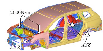
The test method of bodywork static stiffness used by the enterprise was referred to in this research. The test method of bending stiffness is as follows: the boundary constraint condition of bending stiffness is adopted in the test, and the vertical downward loads (1500 N) are placed respectively on the location where the threshold beam intersects with the plane and H point (the design location of the driver’s seat). The test method of torsional stiffness is as follows: the boundary constraint condition of torsional stiffness is adopted in the test, and the torque 2000 N.m is placed on the front spring seat along the positive and negative directions of . According to the test method, constraint and loads are imposed in the finite element model. The simulation model and boundary conditions of the finite element model of body-in-white static stiffness are presented in Fig. 3 and Fig. 4.
Fig. 3Simulation model and boundary conditions of bending stiffness
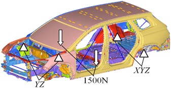
Fig. 4Simulation model and boundary conditions of torsional stiffness
The finite element simulation models above are submitted to the solver for calculation respectively, and the computation results could be checked in the post-processing software (Hyperview). The body-in-white deformation nephogram is respectively presented in Fig. 5 and Fig. 6. It could be observed in Fig. 6 and Fig. 7 that the overall deformation of the body-in-white is relatively less. Regarding the body-in-white deformation, the maximum downward displacement is 0.393 mm under bending working conditions, and the maximum upward displacement is 2.016 mm under torsional working conditions. Regarding the girder, the maximum downward displacement is 0.277 mm under bending working conditions, and the maximum upward displacement is 1.234 mm under torsional working conditions. Regarding the threshold beam, the maximum downward displacement is 0.287 mm under bending working conditions, and the maximum upward displacement is 1.634 mm under torsional working conditions. The deformation is within an allowable range.
Fig. 5Bending deformation nephogram
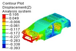
Fig. 6Torsional deformation nephogram
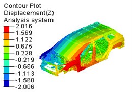
Fig. 7Measurement point diagram of opening part deformation
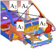
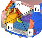
The deformation of the body opening parts could reflect the overall stiffness distribution of the body structure, so the limitations of the bodywork structure design could be found by observing the deformation degree of opening parts. The body opening parts include front windows, front doors, rear doors and rear windows. The measurement points of the body opening parts are arranged as shown in Fig. 7. The opposite angle deformation of opening parts under bending working conditions and torsional working conditions is presented in Table 1. It could be known in Table 1 that the opposite angle deformation of opening parts is relatively less whether the body-in-white is under bending working conditions or torsional working conditions. The deformation is less than the design standard value 5 mm.
Table 1Opening part deformation/mm under bending and torsional working conditions / mm
Opening parts | Location | Deformation under bending conditions | Deformation under bending conditions |
Front window | A1-a2 | 0.002 | –0.117 |
Front window | A3-a4 | 0.004 | 0.109 |
Left front door | B1-b2 | 0.011 | –0.412 |
Left rear door | C1-c2 | –0.205 | 0.580 |
Right front door | D1-d2 | 0.015 | –0.487 |
Right rear door | E1-e2 | 0.216 | 0.323 |
Rear window | F1-f2 | –0.003 | –0.929 |
Rear window | F3-f4 | –0.003 | 0.964 |
The girder deformation displacement in direction in the bending stiffness calculation and the torsional stiffness calculation are obtained. According to Eqs. (1) and (2), the bending stiffness and torsional stiffness of the body-in-white are calculated, which are 13207.77 N/mm and 15711.31 N·m/° respectively. The reference values of the body-in-white bending stiffness and torsional stiffness are 12200 N/mm and 13000 N·m/° in the international standard. Thus, it could be concluded that the studied commercial vehicle has a relatively good body-in-white static stiffness in the same model vehicles.
4. Experimental verification
To verify the accuracy of the finite element simulation results, the bench test was made for the body-in-white static stiffness. Test facilities are composed of static stiffness test-bed, constraint device, loading device and measuring system. Constraint device is composed of crosshead slide blocks, movable hinges and fixed hinges. Loading device consists of force sensor and Lifting jack. Measuring system consists of displacement sensor, multi-channel data acquisition instrument. Before the test, 30 measuring points are selected on the girder, which are symmetrically arranged on the lower surface of the left and right girders; 10 measuring points are selected on the threshold beam, which are symmetrically arranged on the lower surface of the threshold beam. Meanwhile, 16 measuring points are arranged in locations such as front windows, vehicle doors and rear windows. The test of body-in-white bending stiffness and torsional stiffness is presented in Fig. 9 and Fig. 10.
Fig. 9Bending stiffness test
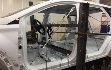
Fig. 10Torsional stiffness test
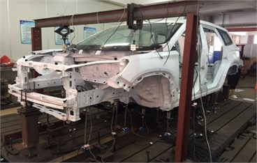
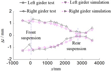
Constraints and loads are imposed in accordance with the method listed in the Section 3.3 in the test. Test procedures are as follows: firstly, a load equivalent to the specified test load is imposed on the bodywork, and the loading and unloading are operated three times to eliminate the influence of fixture interference and welding gaps, so the system could reach a stable measuring state. Next, the preloads of 500 N (bending stiffness test) and 500 N·m (torsional stiffness test) are imposed on the bodywork to eliminate the fixture gap. Finally, the specified load is imposed on the bodywork, and the reading of each sensor is recorded after the system is in a stable condition, the test is repeated 5 times. The consistency check is used for the test data, and the variance of 5 tests is within 0.05 %, which suggests that the test data have relatively good consistency. Moreover, the weighted average of the test data is conducted to draw the bending deformation curve and the torsional deformation curve of the body-in-white. Afterwards, the test curves are compared with the finite element simulation results, as shown in Fig. 11 and Fig. 12. It could be known in Fig. 11 and Fig. 12 that the finite element simulation result is basically consistent with the test result in terms of the bending deformation and torsional deformation of the girder.
Fig. 11Bending deformation curve of girder
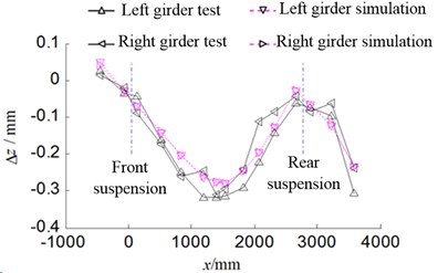
Fig. 12Torsional deformation curve of girder
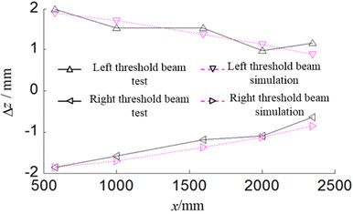
The simulation of bending deformation and torsional deformation of the threshold beam is compared with the test result, as shown in Fig. 13 and Fig. 14. It could be known in Fig. 13 and Fig. 14 that the finite element simulation of bending deformation and torsional deformation of the threshold beam is basically consistent with the test result.
Fig. 13Bending deformation curve of threshold beam
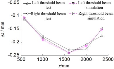
Fig. 14Torsional deformation curve of threshold beam
The opposite angle deformation of opening parts is presented in Table 2. It could be known in Table 2 that the finite element simulation result is basically identical with the test result regarding the opposite angle deformation of opening parts. A relatively great difference is observed between the simulated deformation result and the test results of front windows and rear windows under the bending working conditions. This is because the sensor is not precise enough to detect the relatively less deformation of front windows and rear windows.
Table 2Comparison of opening part deformation test and simulation under bending working conditions
Opening parts | Location | Bending deformation/mm | Torsional deformation/mm | ||||
Test | Simulation | Error | Test | Simulation | Error | ||
Front window | A1-a2 | 0.003 | 0.002 | 33.33 % | –0.128 | –0.117 | 8.59 % |
Front window | A3-a4 | 0.005 | 0.004 | 20.00 % | 0.115 | 0.109 | 5.22 % |
Left front door | B1-b2 | 0.01 | 0.011 | –10.00 % | –0.376 | –0.412 | 9.57 % |
Left rear door | C1-c2 | –0.193 | –0.205 | –6.22 % | 0.552 | 0.580 | 5.07 % |
Right front door | D1-d2 | 0.017 | 0.015 | 11.76 % | –0.527 | –0.487 | 7.59 % |
Right rear door | E1-e2 | 0.223 | 0.216 | 3.14 % | 0.343 | 0.323 | 5.83 % |
Rear window | F1-f2 | –0.004 | –0.003 | 25.00 % | –0.846 | –0.929 | 9.81 % |
Rear window | F3-f4 | –0.004 | –0.003 | 25.00 % | 0.985 | 0.964 | 2.13 % |
The test bending stiffness and torsional stiffness of the body-in-white are calculated using the static stiffness calculation formula, which are then compared with the result of the finite element simulation, as shown in Table 3. It could be known in Table 3 that the bending stiffness test value of the body-in-white sample car is 14314.14 N/mm under this boundary constraint conditions and the finite element simulation value is 13207.77 N/mm with a relative error of 7.73 %. The torsional stiffness test value of the sample body-in-white is 14687.57 N·m/° and the finite element simulation value is 15711.31 N·m/° with a relative error of 7.736.97 %. Regarding the bending stiffness and torsional stiffness of the sample body-in-white, the simulation result is then compared with the test result with the error at an acceptable range of ±10 %, which verifies the validity of the finite element analysis for the body-in-white static stiffness.
Table 3Comparison of simulation result and test results for white-in-body static stiffness
Static stiffness | Simulation value | Test value | Error |
Bending stiffness (n/mm) | 13207.77 | 14314.14 | 7.73 % |
Torsional stiffness(n·m/°) | 15711.31 | 14687.57 | 6.97 % |
5. Conclusions
The simulation analysis and verification of the body-in-white static stiffness is conducted. It could be known in the analysis above that the finite element simulation result is basically consistent with the test result in terms of threshold beam deformation, the opposite angle deformation of opening parts and the bodywork static stiffness. This suggests the validity of the established finite element simulation model. The model could be used for the body-in-white static stiffness analysis under other boundary constraint conditions.
References
-
Chen Shuming, Song Xuewei, Shen Chuanliang, Wang Dengfeng, Li Wei Experimental analysis of static stiffness for vehicle body in white. Applied Mechanics and Materials, Vol. 248, 2013, p. 69-73.
-
Zhang Guo-Sheng, Meng Fan-Liang, Zhang Tian-Xia, Zhang Da-Qian Numerical modeling and stiffness analysis for body in-white of car. Journal of Northeastern University, Vol. 29, Issue 2, 2008, p. 81-84.
-
Helsen J., Cremers L., Mas P., Sas P. Global static and dynamic car body stiffness based on a single experimental modal analysis test. Proceedings of International Conference on Noise and Vibration Engineering, 2010, p. 2505-2521.
-
Wang Yan, Chen Wuwei, Xie Youhao, Deng Shuzhao Application of multi-objective genetic algorithm to body-in-white dynamic performance optimization. Automotive Engineering, Vol. 39, Issue 11, 2017, p. 1298-1304.
-
Zhang Wentao, Wang Zhenhu, Fang Xiangdong, Yang Xuyue, Li Luoxing, Wang Wanlin A calculation method of car body in white's static stiffness based on modal theory. China Mechanical Engineering, Vol. 29, Issue 5, 2018, p. 511-518.
-
Ottaiano Simona Anna, Geluk Theo, Teipen Elmar, El-Kafafy Mahmoud Trimmed body static stiffness identification using dynamic measurements: test methodology and correlation with CAE results. SAE Technical Papers, 2018.
-
Wang Chao, Lü Zhenhua, Lü Yining A research on the effects of windshield on the structural stiffness of vehicle body. Automotive Engineering, Vol. 36, Issue 12, 2014, p. 1539-1545.
-
Wood Ian, Barari Ahmad, Esmailzadeh Ebrahim Using the simple structural beam (SSB) model to optimize and analyze automotive structures for bending stiffness and natural frequency. Proceedings of the ASME Design Engineering Technical Conference, 2014.
-
Mihaylova Pavlina, Pratellesi Alessandro, Baldanzini Niccolò, Pierini Marco Optimization of the global static and dynamic performance of a vehicle body by means of response surface models. 11th Biennial Conference on Engineering Systems Design and Analysis, Vol. 1, 2012, p. 187-196.
Cited by
About this article

The authors would like to thank the financial supports of the Key Natural Science Foundation of Anhui Provincial Universities (Grant No. KJ2019A1154).
