Abstract
In this paper we consider in general form the compilation of a dynamic model of a cantilever rod with a variable cross section that performs bending vibrations. A real mechanical system is a system with distributed parameters. The task of dynamic modeling is the creation of a more convenient calculation scheme. The dynamic model of a rod of an alternating cross section obtained in this case is a discrete system with a concentrated mass at the end of the reduced mass associated with fixing a weightless elastic rod. The problem of determining the parameters of a discrete system is solved from the condition that the kinetic energies of the initial (real) and reduced (discrete) systems are equal. As a result of the work, formulas were obtained that make it possible to determine the reduced mass of the beam and its bending stiffness concentrated at the end of the console. The major goal of this paper is to address the derivation of the frequency equation of flexural vibrating cantilever beam considering the bending moment generated by an additional mass at the free end of beam, not just the shear force. It is a transcendental equation with two unambiguous physical meaning parameters. And the influence of the two parameters on the characteristics of frequency and shape mode was made. The results show that the inertial moment of the mass has the significant effect on the natural frequency and the shape mode. And it is more reasonable using this frequency equation to analyze vibration and measure modulus.
1. Introduction
When dynamically studying a mechanical system, it is necessary to compile a dynamic model of mechanics [1]. The dynamic model is usually a design scheme in which the real parameters of the mechanism are replaced by the reduced ones [2]. The compilation of the model is due to the fact that the real object is a complex mechanical system with distributed parameters, which makes it much more difficult and sometimes impossible to study it [3]. Dynamic model can be made in the form of a discrete system with a limited number of parameters, which greatly facilitates the dynamic investigation of the motion of the system [4, 5]. In technical devices, rods, shafts and beams with a tubular cross section are often used to facilitate the construction. To determine the true loads in the contours of the links of the actuating mechanisms of operating machines, it is convenient to use differential equations describing the processes occurring during the operation of the machines under study. In particular, this applies to various types of hoisting and transport machines [6, 7]. Hoisting devices with a cantilever arrangement of the working organ used in the mining and metallurgical, construction and other industries are subjected to significant overloads during operation [8]. The main reason for this is flexural oscillations of the cantilever beam with parametric excitation caused by a change in the mass of the material being discharged [9, 10]. The study of such devices with the help of differential equations will reveal the causes of overloads of the bearing parts of the drive and suggest measures for their improvement.
2. Materials and methods
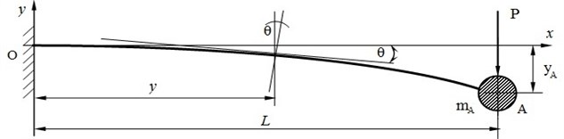
In technical devices and equipment, rods, shafts and beams with a tubular cross section are often used to facilitate the construction. We consider the problem of determining the basic parameters for compiling the dynamic model of an oscillating beam of variable cross section with an internal longitudinal hole of constant radius . These parameters are the reduced mass and the reduced flexural rigidity of the beam [1]. The mass reduction is carried out from the condition of equality of the kinematic energies of the initial (reducible) system and the reduced (dynamic model) of the system [2]. The beam shown in Fig. 1 is considered to be a system with distributed parameters, and in Fig. 2 the reduced system is considered discrete, since the entire mass of the beam is brought to one point A. Such devices are mechanical systems with distributed parameters (see Fig. 1). Such a system can be reduced to a discrete one with a mass concentrated at one point (see Fig. 2).
Fig. 1The diagram of a cantilever beam of variable cross section with a longitudinal aperture
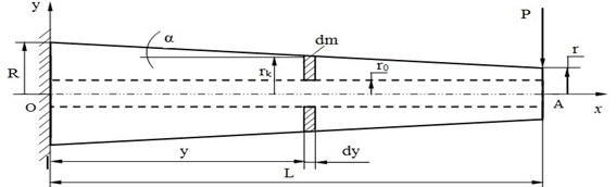
Actually, the problem is solved of bringing the system with distributed parameters (the original cantilever beam) to a discrete view with the mass given to point A , connected to the place of attachment by a weightless elastic rod [3], characterized by flexural rigidity (see Fig. 2). The problem of reducing the mass of a beam is realized from the condition that the kinetic energies of the initial and reduced systems are equal. Kinetic energy the reduced system is determined by means of the formula [1]:
where given on a point in the A mass of beams; the speed of lateral oscillations of the point A.
Fig. 2Calculation scheme of a cantilever beam with a variable cross-section
The kinetic energy of the initial system is determined by means of a definite integral:
where elementary mass; because of the infinitely small thickness of the cross section, occupied by mass and in order to simplify further calculations [4], we assume that the elementary section has the form of a cylindrical, rather than a cone; the whole mass is unevenly distributed over the site OA length rod (beams); – mass of the whole rod; – the mass of the entire rod is the velocity of the point of the elastic line of the bent beam, which coincides with the center of this section . The mass of the elementary section dm (Fig. 1) is defined as the mass of an elementary ring by formula:
where , After the transformations The outer radius of a beam in an arbitrary section located at a distance from the origin; . The volume of the beam:
Beam mass:
The central moment of inertia in the section of the beam located at a distance from the origin of the coordinate axes:
Using formula , we transform the integral Eq. (2) To determine the kinetic energy of the initial system with distributed parameters:
where – velocity of the point of the elastic line of the bent beam [5], which coincides with the center of this section:
In the expression Eq. (4), which determines the kinetic energy of the initial system before a definite integral, we introduce the mass, making the following transformation:
In view of formula Eq. (3) The integral for determining the kinetic energy of the initial system takes the form:
In order to solve the integral you need to find an expression to determine the speed points, coinciding with the center of the section. For this it is necessary to compile and twice integrate the differential equation of the elastic line of the beam under investigation [6]. Differential equation of the elastic line of a beam:
For the convenience of integration, we introduce a new variable, . The differential equation of the elastic line of the beam will take the form:
The first integral that determines the angle of rotation of the section :
where indicated .
By integrating twice the higher-order equation and substituting for zero initial conditions , we obtain the equation of the elastic line of the beam or the deflection equation as a function:
here , а and correspond to constants of integration and :
From the deflection equation Eq. (6) find the reduced flexural rigidity of the beam . It is equal to the reciprocal of the coefficient of force at , , where is denoted:
To determine the speed it is necessary to differentiate with respect to time the deflection equation Eq. (6), in which only the force depends on time [7]. Taking the derivative and squaring it, we find an expression for the velocity:
The resulting expression is substituted in Eq. (5) under the integral sign:
Integration of the expression Eq. (5) in general form, without specific numerical values of the constants , , , , , it is not advisable, as a result a complex dependence occupying several pages of text is obtained [8]. When examining mechanical systems with specified or defined numerical parameters, you can use the MSC Adams software and Ansys program to obtain a specific numerical value of a certain integral. In this case, the kinetic energy formula of the initial system Eq. (8) can be written in the form:
where through the predicted value of a definite integral is indicated. To determine the kinetic energy of the reduced system [9], the speed of the point A is determined using equation Eq. (6) at and:
Then the formula for the kinetic energy of the reduced system Eq. (1) will take the form:
Equating the right-hand sides of the expressions for the kinetic energies of the original Eq. (9) and the reduced Eq. (10) systems [10], we obtain a formula for determining the reduced mass of a cantilever beam of an alternating cross-section with a longitudinal hole of constant diameter:
The resulting formulas for determining the reduced mass and reduced flexural rigidity can be used to compile a dynamic model of a cantilever beam with a variable cross-section with a longitudinal hole.
2.1. Nature of problem parameters
Development of stresses and deflections in beam structures highly depends on the nature of problem parameters. Three most important parameters of a structural problem are boundary condition, loading condition and initial geometry. Several aspects of these three types of problem parameters are described in the following sub-sections.
2.2. Boundary condition
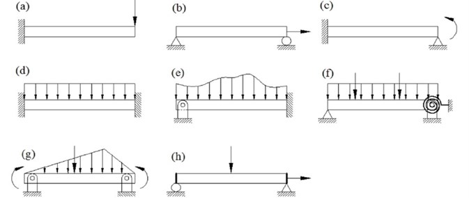
Characteristics of deflection and stress field developed in beam under different loading conditions depend on their boundary conditions. Generally, displacement kinematics is prescribed at boundaries, whereas force kinetics is prescribed sometimes, and mixed boundary condition arises rarely in some complicated beam bending problems. Two classical displacement-based boundary conditions, used for stress and deflection analysis of beam, are fixed-free and simply supported. Many other boundary conditions, such as fixed-simply supported, clamped-clamped, hinged-clamped, simply supported-elastically restrained, hinged-hinged, stiffened lateral ends, are also prescribed for deflection analysis of beam structures. These different types of classical and nonconventional boundary conditions of beams are shown in Fig. 3. When beam is subjected to combined bending and stretching stress field, membrane boundary condition is also prescribed in addition to displacement boundary conditions.
Fig. 3Different types of boundary and loading condition of beam: a) fixed-free under concentrated transverse load, b) simply-roller supported under concentrated in-plane load, c) fixed-simply supported under pure bending moment, d) clamped-clamped under uniformly distributed load, e) hinged-clamped under non-uniformly distributed load, f) simply supported-elastically restrained under combined concentrated and distributed transverse load, g) hinged-hinged under transverse concentrated, distributed load and bending moment, h) roller-simply supported with stiffened lateral ends under combined bending and in-plane load
2.3. Numerical method
Improvement in the modern-day computers enables realistic simulation of structural behavior at loaded condition. Engineers and scientists generally use finite element package to find potential of a structure in actual working environment. For this purpose, a structure is modeled in virtual environment using nonlinear finite element (NFEM) analysis software. For design of beam like structures, several commercial finite element packages such as MSC/NASTRAN, ANSYS, ABAQUS, etc. are being extensively used in industry nowadays.
2.4. Type of material
As the present review work mainly focuses on beam deformation up to yield limit, the material behavior remains linear elastic. Material is broadly classified into two major categories, namely isotropic and anisotropic both of which show nonlinear stress-strain behavior beyond their elastic limit. Material nonlinearity associated with post elastic deformation is mainly dealt with in the theory of plasticity, which is a vast subject in itself, involving various types of material modeling and a number of theories predicting stress-strain relations.
2.5. Statement of the problem
Beam length 500 mm, force 1000 N, beam diameter 50 mm, Young’s modulus of elasticity for steel 210×103 MPa, than area 3.14·(50)2 = 1962.5 mm2, area moment of inertia /64 = 306640.625 mm4, bending moment for cantilever beam = 1000·500 = 5×10⁵ N·mm, maximum stress:
3. Results and discussion
Thus, formulas were obtained for determining the reduced mass and flexural rigidity-the (see Fig. 3(a)) parameters necessary for the investigation of transverse oscillations of cantilever beams with a variable cross-section.
Fig. 4Scheme of the beam elements
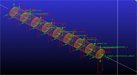
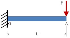
Fig. 5Computed plot of the maximum deformation point A (see Fig. 4)
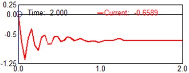
Fig. 6Computed plot of the (beam elements 8) position Y
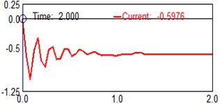
Fig. 7Computed plot of the (beam elements 7) position Y
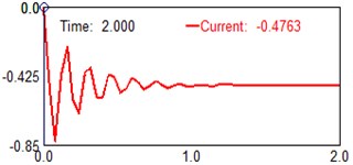
Fig. 8Computed plot of the (beam elements 6) position Y
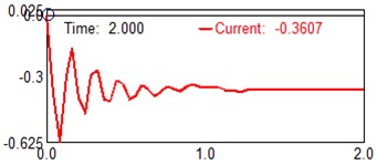
Fig. 9Computed plot of the (beam elements 5) position Y
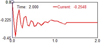
Fig. 10Computed plot of the (beam elements 4) position Y
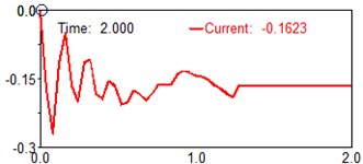
Fig. 11Computed plot of the (beam elements 3) position Y
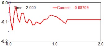
Fig. 12Computed plot of the (beam elements 2) position Y
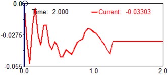
Fig. 13Computed plot of the (beam elements 1) position Y
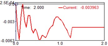
Fig. 14Computed plot of the shear force diagram
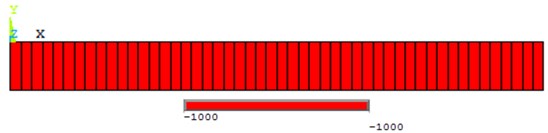
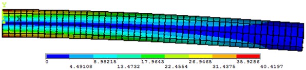
Fig. 15Computed plot of the bending moment diagram (line stress)
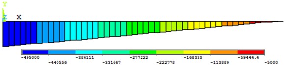
Fig. 16Computed plot of the Von Mises stress plot
4. Conclusions
As a result of this study, instead of a mechanical system with distributed parameters, one mass discrete system (dynamic model) is obtained, connected with a pinch point by a weightless elastic rod. Formulas are derived that make it possible to determine the reduced mass and the flexural rigidity of a rod of variable cross section-parameters that allow one to investigate bending vibrations of similar systems. The frequency equation of cantilever beam with an additional mass exciting flexural vibration was derived considering the rotary inertial moment of inertia of an attached mass, including the shear force. It is a transcendental equation, and it contains two parameters with unambiguous physical meaning, which can be defined as the ratio of rotary mass moment of inertia and the ratio of the mass, respectively. These two parameters effect both the natural frequency and the shape mode of the beam. A proper dynamic model has been development within MSC/ADAMS and ANSYS software to provide information on the feasibility of the proposed design solution. Simulation tests have been carried out and results are discussed for validating the proposed design and characterizing its operation. Harmonic analysis was also accompanied by computer modelling. Setting damping parameters is required for calculation. The MSC/ADAMS and ANSYS software has multiple damping parameters, but all they do not depend on stress-stain state of construction. It is possible to use only the frequency dependent damping (see Figs. 14-16). As the ratio of rotary mass moment of inertia increases, the natural frequency climbs. Even a little increment of the ratio may cause higher variance between considering and not considering the rotary mass moment of inertia, especially for the high natural frequency. And the ratio of the rotary mass moment of inertia also effects the mode shape of this system. The higher the serial number of mode shape investigated is, the more obvious the divergence becomes.
References
-
Rudavskii Y. K., Vikovich I. A. Forced flexural-and torsional vibrations of a cantilever beam of constant cross section. International Applied Mechanics, Vol. 43, Issue 8, 2007, p. 912-923.
-
Zhou D., Ji T. Dynamic characteristics of a beam and distributed spring-mass system. International Journal of Solids and Structures, Vol. 43, Issue 18, 2006, p. 5555-5569.
-
Rossit C. A., Laura P. A. A. Free vibrations of a cantilever beam with a spring-mass system attached to the free end. Ocean Engineering, Vol. 28, Issue 7, 2001, p. 933-939.
-
Banerjee J. R. Free vibration of beams carrying spring mass systems-a dynamic stiffness approach. Computers and Structures, Vol. 104, 2012, p. 21-26.
-
Digilov R. M., Abramovich H. Flexural vibration test of a beam elastically restrained at one end: a new approach for Young’s modulus determination. Advances in Materials Science and Engineering, 2013, p. 329530.
-
Idriss M. I., Seed B. H. Seismic response of horizontal soil layers. Journal of the Soil Mechanics and Foundation Division, Vol. 94, Issue 4, 1968, p. 1003-1031.
-
Cascante G., Santamarina C., Yassir N. Flexural excitation in a standard torsional-resonant column device. Canadian Geotechnical Journal, Vol. 35, Issue 3, 1998, p. 478-490.
-
Laura P. A. A., Pombo J. L., Susemihl E. A. A note on the vibrations of a clamped-free beam with a mass at the free end. Journal of Sound and Vibration, Vol. 37, Issue 2, 1974, p. 161-168.
-
Binghui Wang, Zhihua Wang, Xi Zuo Frequency equation of flexural vibrating cantilever beam considering the rotary inertial moment of an attached mass. Mathematical Problems in Engineering, 2017, p. 1568019.
-
Janat Musayev, Algazy Zhauyt Analysis of disturbing influence of traffic load on soil body. Advances in Materials Science and Engineering, 2015, p. 318289.
About this article

